|
Joy Stick Controller |
|
|
This project
controls two servo motors - both clockwise and anticlockwise and has
variable speed.
You can use the Joy Stick to "pan and tilt" a remote camera
or provide "left-right-up-down" action for a crane or an animation
on your model layout.
The project also tests servo motors.
The CIRCUIT
The circuit is fairly simple.
The input from the Joy Stick has been separated into two sections to
make detection easy and this requires 2 inputs.
A pot is connected to another input line and 2 more lines are required
for the servos. Pin 8 is connected
to 0v and pin 1 is connected to the supply. The only unused pin is
GP3 (Input ONLY),
Most of the
work is done by the micro. It uses a technique of charging a capacitor
via a resistor and determining how long it takes to charge, to work out
which switch is pressed or the position of the pot.
It then outputs a 1mS or 2mS pulse to one of the servo motors to create
clockwise or anticlockwise rotation of the output shaft and the speed of
rotation can be set by adjusting the pot. The two LEDs on the output
pins let
you see the pulses being delivered to the servo's when the project is
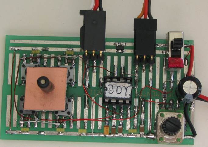
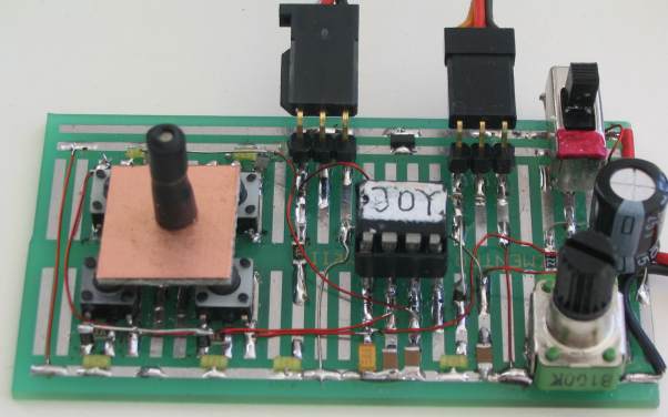
used to test these devices. The photo's below show the circuit built on
prototype board:
THE JOY
STICK
There are 7 different (actually more) combinations of positions for the
joy stick and we need to decode them and work out what to do with the
result.
This is too many resistance-values for a single input and so we have
used two inputs with 3 resistance-values for each plus the possibility
of all switches being pushed at the same time.
The resistance values we have used are 22k and 47k. When 2 switches
are pressed, the resistors are in parallel to produce 15k, but only 22k and
47k is detected in this program.
The program creates a loop
that detects up to 19k, to produce an output of loop=1, then up to 38k
for a value of loop=2 and higher than 38k for a value of loop=3. But if
the program keeps looping for 10 loops, it determines that no button is
pressed and creates a value of 4. The change-points are mid-way between the
resistance-values we have used and thus any tolerances on the capacitors and
resistors can be accommodated.
This means a resistance of 15k produces a value of 1, 22k produces a value of 2 and 47k
produces a value of 3. This is most important as we don't want the
cut-off points to be on
the border as the program may
produce an output of 1 instead of 2. The project is fairly voltage
sensitive and if the right-hand buttons are not detected, the battery
voltage is low.
THE SERVO
A servo module
consists of a motor and gearbox, with a PC board containing the electronics to
drive the motor in clockwise and anticlockwise direction. The
electronics also detects the width of the incoming pulse to drive the
motor to mid-position and also other positions, but this feature is not
used in this project.
The motor is connected to the positive rail of the supply via a bridge
of transistors within the servo and the red and black wires from the module are
taken to the positive and negative of a battery to provide the current
to drive the motor.
The third lead (white) is the control line and this is taken to the
micro.
This line needs a pulse and the maximum repetition-rate accepted by the
servo is every 18mS - it will accept a longer timing between pulses.
This is the timing between pulses, the actual pulse-width is very short,
between 0.9mS and 2.2mS.
If the pulse is less than 1mS duration (wide) the servo will travel
fully in the anticlockwise direction.
If the pulse is 2mS, the servo will travel in the clockwise direction.
If the pulse is 1.5mS, the servo will travel to the mid position.
If the time between pulses is longer than 18mS, the speed of rotation is
decreased.
This is what we have done. We have provided a 1mS or 2mS pulse and
created a long time-interval between pulses to produce a reduced rate of
movement.
The program looks at the position of the pot and adds a number of
milliseconds between each pulse to produce these long time-intervals.
As the resistance of the pot is increased, the pulses are less frequent
and the speed decreases.
SPEED
This is the first time a speed feature has
been added to a servo. The project can vary the speed from full rpm to a
few pulses per second. It takes about 12 pulses to move 180°.
Sometimes you want to move an object a small distance. A servo is not an
ideal driver for this requirement as the smallest step
is about 1/25th of a revolution or 15°. Even when a single pulse
is delivered to the servo, the increment is about 15°.
Unfortunately this is the finest control we can get from a servo. That's
why you use a stepper motor if you want very small incremental steps.
However if the pulses are delivered at about 5 per second, the rotation
will be slow but fairly smooth. You will be able to set this via the
pot.
|
INSTRUCTIONS FOR USE Connect two servos and move the Joy Stick to turn the appropriate servo in the desired direction. If the project fails to work, check the batteries as the voltage on the chip must be 5.5v to detect the switches and the correct position of the pot, (via charging the 100n caps) and a low voltage will prevent the right switches being detected. |
CONSTRUCTION
You can build the circuit on any
type of PC board and we have used a small piece of experimenter board as
it has been especially designed for through-hole components and
surface-mount devices. With all the lands on the top surface, you can
see the components and wiring at the same time and this makes
development very easy and you can easily change any of the components.
The kit comes with all the parts you need to get the
project working, including a pre-programmed chip and the experimenter
board, developed by Talking Electronics.
However if you want to modify the program you will need a PICkit-2 programmer and this comes
with a CD containing all the software needed for In-Circuit
Programming.
You will also need a lead (comes with PICkit-2) to connect the programmer to your lap top via
the USB port and an adapter we call 6pin to 5 pin
Adapter to connect the PICkit-2 to a programming socket on a PC
board. This is all covered in our PIC-2 USB Burner project.
Making the Joy
Stick
The Joy Stick consists of 4
buttons soldered to the PC board with a small square piece of PC board
glued to the tops of the switches with Araldite.
A 15mm x 3mm machine screw (machine bolt) is soldered to the underside of the PC
board before gluing to the buttons. A small length of heatshrink is then
shrunk over the screw to create a lever.
All the other components are soldered to the board as shown in the
photos above, using fine tinned copper or fine enamelled wire to
create the wiring.
Adjusting
the Range
The angular movement of the
output shaft can be adjusted (limited) by setting the width of the
forward and/or reverse pulse.
When the output shaft reaches the end of its angular movement, any
further pulses are neglected by the servo and no current is consumed
(other than a few mA for the electronics). In other words the motor does
not get stalled.
However the rotation can be adjusted (limited) so that the output
shaft does not reach the end of its travel by adjusting the value
of the sub-routine called: acw (anticlockwise pulse width). [You can
also (or instead) adjust the clockwise pulse-width]
The sub-routine "acw" is effectively a delay (made up of loops) that is
loaded with a value from 1 to 250 (for 1 to 250 loops) and each loop
represents 4uS delay. This means a value of 250 = (4 x 250) uS = 1,000uS
= 1mS.
By adding an extra instruction: call _1mS to the: call _acw
we can create a delay from 1.004mS to 2mS and thus prevent the output
shaft reaching the end of its travel.
If we load acw with .125 we get a total delay of 1.5mS and the output
will only travel to mid-position (90 degrees). A value of .60 (decimal
sixty) will allow the shaft to travel 135 degrees. A value of .20
(decimal twenty) will allow the shaft to travel nearly 145
degrees. You must remove the "call _1mS" to allow the shaft to
rotate to the 180 degrees position.
You can also adjust the amount of travel to the final device you are
activating, by adjusting the length of the
arm on the output of the servo. By combining these two methods you can
get a wide variety of activations.
|
|
|
Here are the files you will need:
JoyStick.asm
JoyStick-asm.txt
JoyStick.hex
;*******************************
;;JoyStickController.asm
;
;drives 2 servo motors forward and reverse
;10-11-2010
;*******************************

	list	p=12F629
	radix	dec
	include	"p12f629.inc"

	errorlevel	-302	; Don't complain about BANK 1 registers

	__CONFIG	_MCLRE_OFF & _CP_OFF
                      & _WDT_OFF & _INTRC_OSC_NOCLKOUT  ;Internal osc.

;_MCLRE_OFF  - master clear must be off for gp3 to work as input pin

;******************************
; variables - names and files
;*****************************

temp1		equ 20h	;
temp2		equ 21h	;

Sw_FlagT	equ	25h	;switch flag top
Sw_FlagB	equ	26h	;switch flag bottom
count	equ	27h	;loops of discharge time for 100n
PotValue	equ 	28h 	;value of pot


;***************************
;Equates
;***************************
status		equ	0x03
rp1		equ	0x06
rp0		equ	0x05
GPIO 		equ 	0x05


status		equ	03h
option_reg		equ 	81h


		; bits on GPIO

pin7		equ	0	;GP0  left servo motor
pin6	 	equ	1	;GP1  right servo motor
pin5		equ	2	;GP2  100k speed pot
pin4		equ	3	;GP3  Input ONLY - not used
pin3		equ	4	;GP4  input from 2 top buttons
pin2		equ	5	;GP5  input from 2 bottom buttons


		;bits

rp0		equ	5	;bit 5 of the status register

;**********************
;Beginning of program
;**********************
	org	0x00
	nop
	nop
	nop
	nop
	nop
SetUp	bsf	status, rp0 	;Bank 1
       	movlw	b'11101000'	;Set TRIS  GP0,1,4 out
	movwf	TRISIO
	bcf	status, rp0		;bank 0
	movlw   	07h         		;turn off Comparator ports
        	movwf  	CMCON       	;must be placed in bank 0
        	clrf 	GPIO       		;Clear GPIO of junk
	goto 	Main


;****************
;delays	*
;****************

_uS	movlw	08Ch
	movwf	temp1
	decfsz 	temp1,f
	goto 	$-1
	retlw 	00


	;delay for pulsing servo anticlockwise

acw
	movlw	60h
	movwf	temp1
	decfsz 	temp1,f
	goto 	$-1
	retlw 	00


_1mS	nop
	decfsz 	temp1,f
	goto 	_1mS
	retlw 	00


_10mS	movlw	0Ah
	movwf	temp2
	nop
	decfsz 	temp1,f
	goto 	$-2
	decfsz 	temp2,f
	goto 	$-4
	retlw 	00

_15mS	movlw	.15
	movwf	temp2
	nop
	decfsz 	temp1,f
	goto 	$-2
	decfsz 	temp2,f
	goto 	$-4
	retlw 	00


_18mS	movlw	.18
	movwf	temp2
	nop
	decfsz 	temp1,f
	goto 	$-2
	decfsz 	temp2,f
	goto 	$-4
	retlw 	00


	;delay to create value for pot for servo speed

PotDel	movlw	0A0h
	movwf	temp1
	decfsz 	temp1,f
	goto 	$-1
	retlw 	00


;***************************
; Sub Routines 	  *
;***************************


	;position of pot creates a value in PotValue

Pot	bsf	status,rp0
	bcf	trisio,2		;Make GP2 output
	bcf	status,rp0
	bcf	gpio,2		;make GP2 LOW
	call	_1mS		;create delay to discharge 100n
	bsf	status,rp0
	bsf	trisio,2		;Make GP2 input
	bcf	status,rp0
	clrf	PotValue
	call	PotDel
	incf	PotValue,f
	btfss	gpio,2		;is input HIGH?
	goto	$-3
	retlw	00		;returns with a value in PotValue

	;SwTop sets bit 1,2,3,4 in Sw_FlagT file

SwTop	clrf	Sw_FlagT
	clrf	count
	bsf	status,rp0
	bcf	trisio,4		;Make GP4 output
	bcf	status,rp0
	bcf	gpio,4		;make GP4 LOW
	call	_1mS		;create delay to discharge 100n
	bsf	status,rp0
	bsf	trisio,4		;Make GP4 input
	bcf	status,rp0
	call	_uS
	incf	count,f
	movlw	.10		;create 10 loops to definitely return
	xorwf	count,w
	btfsc	status,z
	goto	$+3
	btfss	gpio,4		;is input HIGH?
	goto	$-7		;count exits with 1-4
	decfsz	count,f
	goto	$+3
	bsf	Sw_FlagT,1	;both top buttons pressed
	retlw	00
	decfsz	count,f
	goto	$+3
	bsf	Sw_FlagT,2	;left top button pressed
	retlw	00
	decfsz	count,f
	goto	$+3
	bsf	Sw_FlagT,3	;right top button pressed
	retlw	00
	bsf	Sw_FlagT,4	;no buttons pressed
	retlw	00

	;SwBott sets bit 1,2,3,4 in Sw_FlagB file

SwBott	clrf	Sw_FlagB
	clrf	count
	bsf	status,rp0
	bcf	trisio,5		;Make GP5 output
	bcf	status,rp0
	bcf	gpio,5		;make GP5 LOW
	call	_1mS		;create delay to discharge 100n
	bsf	status,rp0
	bsf	trisio,5		;Make GP5 input
	bcf	status,rp0
	call	_uS
	incf	count,f
	movlw	.10		;create 10 loops to definitely return
	xorwf	count,w
	btfsc	status,z
	goto	$+3
	btfss	gpio,5		;is input HIGH?
	goto	$-7		;count exits with 1-4
	decfsz	count,f
	goto	$+3
	bsf	Sw_FlagB,1	;both lower buttons pressed
	retlw	00
	decfsz	count,f
	goto	$+3
	bsf	Sw_FlagB,2	;left lower button pressed
	retlw	00
	decfsz	count,f
	goto	$+3
	bsf	Sw_FlagB,3	;right lower button pressed
	retlw	00
	bsf	Sw_FlagB,4	;no buttons pressed
	retlw	00


;****************************************************************
;* Main 					*
;****************************************************************

Main	call	SwBott		;to detect 2 lower buttons
	btfsc	Sw_FlagB,4  	;bit 4 set if no buttons pressed
	goto	_b		;go to detect top buttons
	call	Pot		;determine servo speed
	btfsc	Sw_FlagB,2	;left lower button pressed
	goto	$+9
	btfss	Sw_FlagB,3	;right lower button pressed
	goto	Main
	bsf	gpio,0		;creates clockwise motion
	call	_1mS		;for clockwise pulse
	call	_1mS		;for clockwise pulse
	bcf	gpio,0
	call	_18mS
	goto	$+5
	bsf	gpio,0		;creates anticlockwise motion
	call	acw		;anticlockwise pulse
	bcf	gpio,0
	call	_18mS
	decfsz	PotValue,f
	goto	$-2
	goto	Main


_b	call	SwTop		;to detect 2 top buttons
	btfsc	Sw_FlagT,4  	;bit 4 set if no buttons pressed
	goto	Main		;
	call	Pot		;determine servo speed
	btfsc	Sw_FlagT,2	;left top button pressed
	goto	$+9
	btfss	Sw_FlagT,3	;right top button pressed
	goto	_b
	bsf	gpio,1		;creates clockwise motion
	call	_1mS		;for clockwise pulse
	call	_1mS		;for clockwise pulse
	bcf	gpio,1
	call	_18mS
	goto	$+5
	bsf	gpio,1		;creates anticlockwise motion
	call	acw		;anticlockwise pulse
	bcf	gpio,1
	call	_18mS
	decfsz	PotValue,f
	goto	$-2
	goto	Main

END |
The
PROGRAM
The micro starts at SetUp routine,
then goes to Main where it
constantly loops the two Joy Stick inputs by accessing one of
the lines and discharging the 100n capacitor. It then makes the line an
input and calls a delay. It looks to see if the voltage on the 100n is
above about 1.5v as this will indicate a HIGH. It increments a counter
and loops up to ten times. If one of the buttons is pressed, the
line will see a HIGH after 3 loops and thus the sub-routine returns with
a bit set in Sw_FlagT for a top button or Sw_FlagB for a bottom
button. Bit1 is set if
both switches are pressed, Bit2 is set if the left switch is pressed,
bit3 is set if the right switch is pressed and bit4 is set to signify no
switch is pressed.
This result is used in Main to create a repeat "looking-loop" if no switch is pressed,
but if a switch is pressed, the Pot sub-routine is called to determine
the position of the potentiometer.
The program detects 12 positions for the pot by firstly discharging the
100n then creating a timing loop and counting the number of loops to
charge the 100n to a point where the input line sees a HIGH. This
is approx 1.2 - 1.5v.
The instructions in Main then turn on an output for one of the servo
motors for 1mS or 2mS, depending on the button that has been pressed,
then turns off the output. A delay is then created of 18mS duration (if
the pot has the lowest resistance) and this is increased by 18mS for each
additional
position of the pot.
PROGRAMMING THE
CHIP
The kit comes with a pre-programmed PIC chip but if you want to program
your own chip or modify the program, the .hex file is available as well
as the assembly file, so you can see how the program has been written
and view the comments for each line of code.
The PIC12F629 is one of the smallest micros in the range but you will be
surprised how much can be achieved with such a tiny micro.
Even a program as simple as this is not easy to put together and if you
want to change any of the features, you should do things in very small
steps and stages so that each can be tested before adding more
code.
This is what we have done. We produced the program, one small step at a
time.
We had to firstly work out a routine to produce a value of 1,2,3,4 for
the Joy Stick switches, then create a pulse of the correct duration to
create clockwise and anticlockwise rotation.
When this was done we needed to create an output for the pot and add the
delay to the program to create the speed.
If you want to change anything, you will have to buy a programmer ("burner")
called a PIC-2 USB Burner if you are using a laptop. It is the cheapest and best on the market
and comes with
a USB
cable and CD containing the programs needed to "burn" the chip.
If you are using a desk-top and/or tower with a serial port, you can use
a cheaper programmer called MultiChip Programmer from Talking
Electronics. You
will also need NotePad2 to write your .asm program. This can be
downloaded from Talking Electronics website. You will use
JoyStick.asm or
JoyStick-asm.txt as a template for your
program, plus a 6 pin to 5 pin connector that fits between the burner
and the project. This is also available on Talking Electronics website.
To be able to modify the chip you will need a programming socket and PC
board for the socket.
You can then put the chip into the socket and program it, then re-fit it into this project for execution.
PROGRAMMING LANGUAGE
There are a number of kits, programs and
courses on the market that claim and suggest they teach PIC Programming.
Most of these modules and courses use a PIC microcontroller as the chip carrying out
the processes, but the actual programming is done by a proprietary
language invented by the designer of the course.
Although these courses are wonderful to get you into "Programming
Microcontrollers" they do not use any of the terms or codes that apply
to the PIC microcontroller family.
All our projects use the 33 instructions that come with the PIC
Microcontroller and these are very easy to learn.
We use the full capability of the micro and our pre-programmed chip is
less than the cost of doing it any other way.
In addition, anything designed via our method can be instantly
transferred to a PIC die and mass produced. And we use all the input
pins and all the memory of the chip. The other approaches
use less than 25% of the capability of the memory and one of the pins is not available.
In fact it would be difficult to reproduce this project via any of the opposition
methods. It would require a larger chip and more expense.
You can use our method or the opposition. Just be aware that the two are
not interchangeable.
Ours is classified as the lowest "form" (level) of programming - commonly called
machine code - invented in the early days of microprocessors - and now
called mnemonic programming as each line of code is made up of
letters of a set of words. The opposition uses a higher level language
where one instruction can carry out an operation similar to a
sub-routine.
But you have to learn the "higher level language" in order to create a
program. And this requires a fair amount of skill and capability.
It sounds great and it is a good idea. But if you want to learn PIC
programming, it does not assist you. It is "a step removed" from
learning PIC language. The other disadvantage of the opposition is the
"overhead." The 1,000 spaces allocated for your program is filled with
pre-written sub-routines. You may require only 10 of these sub-routines but ALL
of them are loaded in the memory space. And they take up all the memory.
You have no room for your own program.
To get around this the opposition uses the 128 bytes in EEPROM to deliver
instructions on how to apply the sub-routines. This provides about 30 powerful instructions using their
language called BASIC (or a similar language).
It's a bit like selling a diary filled with all the paragraphs you need
to express yourself, and leaving a few blank pages at the back for you
to write single lines such as: see page 24, paragraph 7, see page 63
paragraph 4, to create your diary entries.
It depends on how much you want to be in charge of writing a program. Using
our method is like writing your own auto-biography. Using the opposition
is like getting a "ghost writer."
When using a higher level language to create a program, you have absolutely no
idea how the code is generated for the micro.
In some of the developmental kits, the code is "locked away" and you are
NEVER able to access it.
Everything runs smoothly until a fault appears. With our method you can
see the code. With the other methods, you cannot see the code - it's
like doing key-hole surgery without the advantage of an
illuminated endoscope to see what you are doing.
Everything has its place and our method of hand-assembly is only
suitable for very small micros and you will eventually need to "learn a
high level language." The PIC12F629 has over 1,000 locations for code
and this equates to more than 20 pages when printed, so this is about
the limit to doing things by hand.
But our drive is to show how much can be done with the simplest devices
on the market, at the lowest cost.
Anyone can show you high-technology at a high price but this is not
where you start and this is not where you get enthusiasm.
We provide the things to get you started. That's the difference.
10/11/2010