|
Metal Detector MkII |
This project is an extension of
Metal Detector MkI,
and shows how metal objects are detected. It is the second in a series of
circuits and allows a great deal of experimentation, especially if you
have a CRO (Cathode Ray Oscilloscope) and a few items to detect. You can view the waveforms and
see exactly how they alter as an object is brought into the field of the
coil.
Kits for
Metal Detector kit MkII $15.00
plus postage
See the following site for lots
of projects on metal detectors:
Geotech
See also our:
Metal Detector Article
See also Nail Finder - detects
small objects
There are a number of ways to detect a metal object and alter the
operation of a circuit so that an output is produced.
Metal detectors will detect ferrous (iron, steel, stainless steel) as
well as non-ferrous (copper, tin, gold, lead, silver, aluminium) as well
as alloys (brass, cupro-nickel, pewter etc).
Depending on the complexity of the circuit, a metal detector will be
able to discriminate between a lump of gold and an aluminium ring-pull
from a drink-can.
The circuit we have presented in this project is very simple and works
on the principle of detecting the amplitude of a waveform. This is
called AMPLITUDE MODULATION.
When a metal object is placed inside the detecting coil, some of the
magnetic flux passes into the object and creates a current called an
eddy-current. This "uses-up" some of the
magnetic flux and thus less flux is available for the receiving coil.
This produces a lower output from the coil and causes the second transistor in the circuit to be turned
OFF
slightly and the voltage on the collector rises. This allows the
third and fourth transistors to oscillate and pass a signal to the fifth
transistor to drive a mini speaker.
Actually, both the amplitude AND the frequency of the circuit change
when a metal object is detected, but we are only detecting the reduced
AMPLITUDE.
As you can see, the circuit consists of a number of BUILDING BLOCKS. All
you have to do is understand how each block works and you will
understand the whole circuit. CONSTRUCTION
The concepts of TALKING ELECTRONICS is to explain how various building
blocks operate so you can design your own projects. You can take any of
the blocks and add them to your own project, but it will be necessary to connect them together correctly.
That's why you have to read our discussion articles, to learn how to
interface different blocks.
WHAT TYPE OF
CIRCUIT IS IT ?
A customer asked: What type of circuit is it?
This circuit has never been given a name.
That's because it is different to all the other circuits.
The closest name we can apply is "GRID DIP"
detector. The GRID DIP Detector circuit is a very old and
comes from the days of valves. A valve had an input pin called the GRID.
When the voltage on the grid was increased or decreased, the value
produced a magnified output. That's what we call AMPLIFICATION.
In the old valve circuit, a coil and capacitor arrangement (called a
TUNED CIRCUIT) was placed near a project that contained an oscillator.
When the frequency of the project was the same as the frequency of the
Tuned Circuit, the voltage sent to the grid reduced and that's why it
was called a GRID DIP Detector.
Our circuit works in exactly the same manner.
The first coil and capacitor form a TUNED CIRCUIT and when a piece of
metal is placed near the coil, the AMPLITUDE of the oscillation will
reduce. The second coil picks up the amplitude and amplifies the signal.
When the amplification reduces, the second transistor has a gain of
about 100 and the reduction in amplification will be a lot greater. For
instance, if the amplitude of the main oscillator is reduced by 1mV, the
second coil will see a reduction of nearly 1mV and the output of the
transistor will be reduced by about 70mV. This allows the transistor to
turn off slightly and the next 3 transistors produce a buzz in the
speaker. (However the change will only be a few mV).
You can consider this circuit consists of three building blocks:
1. The first block is a FEEDBACK OSCILLATOR, consisting of the
first transistor, 70 turn coil 47n and the 50 turn coil.
The first transistor is turned on via the diode in the emitter
of the second transistor. This diode receives its turn-on bias from the
1k8 resistor.
The resistance of the Rx (receiving coil) is very small and the base of
the first transistor sees a "turn-on" voltage from the voltage
across the diode.
The variable resistor in the emitter starts at a low value for our
description of the circuit.
The first transistor has a high gain at this point in time and the Tx (transmitting coil) and 47n form a tuned circuit with a frequency of
approx 15kHz.
The power rail is stabilized by the 5v6 zener and a small amount of
noise is always present in any circuit and causes a small waveform to
be produced by the coil and capacitor.
This waveform is passed to the receiving coil (through the air) and a small voltage is
produced across it.
Since the end of the receiving coil connected to the diode, it is fixed and rigid
and the
signal produced by the coil is passed to the base of both
transistors. The coil is connected so the voltage it produces turns the
first transistor ON harder and thus the waveform produced by the tuned circuit
is increased.
Since the resistance of the pot is a minimum, the amplitude of the
waveform will be a maximum and this will have the effect of turning
ON the second transistor so the voltage on the collector
will be very low. The signal on the collector will be a waveform but
this is smoothed by the 100n capacitor.
As the resistance of the pot is increased, the voltage on the
emitter will increase and the base-to-emitter voltage will be LESS, so the transistor will not be turned on as much.
The
waveform produced by the tuned circuit will reduce.
This will be reflected in the receiving coil and the second transistor
will also get turned off slightly. The voltage on the collector will
rise and this will be passed to the second building block.
When a metal object is placed in the centre of the coil, some of the
flux enters the object and causes EDDY CURRENTS in it and this flux is
lost. This the receiving coil does not get the full amplitude of flux
and the transistor is turned off a small amount. This increases
the voltage on the collector of the second transistor and causes a tone
to be produced by the next three transistors.
2. THE VOLTAGE CONTROLLED OSCILLATOR - transistors 3 and 4.
The voltage controlled oscillator is simply a direct-coupled high-gain
amplifier with a 10n feedback capacitor to provide oscillation.
When a voltage appears on the base of the third transistor, it turns ON and this turns on the PNP transistor.
The voltage on the collector of the PNP transistor rises and this pulls
one end of the 10n capacitor (via a 1k resistor) towards the positive
rail.
The other end of the capacitor is connected to the base of the third
transistor.
This turns ON the third transistor.
They keep turning ON until both are fully saturated (turned on). This
happens very quickly and during this time the 10n capacitor starts to
charge. The charging current flows through the base-emitter junction of
the third transistor and as the capacitor charges, it develops
a voltage across it. This causes the charging current to reduce. The third transistor gradually turns off and
this turns the fourth transistor off slightly. The voltage on the
collector of the fourth transistor drops and the voltage across the 10n
capacitor causes the third transistor to turn off completely. This turns
off the fourth transistor and now both are fully turned off.
The 10n discharges through the 56k and the cycle repeats. The capacitor
takes a very short time to charge and a longer time to discharge. This
is why the output consists of very short spikes.
Now we come to the reason why the frequency alters.
As the voltage from the previous building block rises, the
charge-time for the first 10n capacitor is less and thus the first
transistor in the oscillator circuit is turned on in a shorter period of
time. This capacitor is discharged when the two transistors are
turned off and to lead of the second 10n is taken to near the 0v rail by
the 1k resistor in series with another 1k resistor and the base of the
driver transistor. It's fairly complex and if you have a CRO, you will
notice the waveforms on the 10n capacitors go below the 0v rail.
This is how the two-transistor direct-coupled amplifier turns into a
variable-frequency oscillator.
3. THE DRIVER TRANSISTOR. The output of the oscillator is
connected to a driver transistor via a 1k resistor. This resistor
prevents high currents flowing when both transistors are turned on. The
driver transistor is directly connected to an 8 ohm speaker. The 18R
resistor reduces the volume and prevents large spikes appearing on the
power rails. The result is a clicking sound.
For this type of circuit to be successful, the supply voltage must be
maintained absolutely rigid for the detecting section. This is very difficult to do as the battery
voltage changes as it gets older and all the semiconductor devices
change according to the temperature. The supply voltage must be as
stable as possible as the circuit is detecting a very small change in
amplitude and the supply voltage has an effect on the size of the
signal. The circuit uses a zener diode to create a fixed supply but as
the temperature of the diode heats-up with current-flow, the
circuit-settings change and a tone is gradually produced by the speaker.
This has to be stopped by adjusting the pot on the emitter of the first
transistor. This constant resetting of the circuit is called INSTABILITY
and is one of the downfalls of the design.
However, for a simple circuit it offers very good sensitivity and an
audio output.
We have more metal detector circuits in the pipeline and will be added
as soon as possible.
Metal detector circuits are a very big part of industry, not only to
detect metal particles in food but also hidden objects on persons
entering various venues.
They are also used to detect the difference between iron compounds and
gold - such as the latest gold detectors.
They are also used to detect coins for vending machines and in this
instance they are generally called "coin comparators." Metal detection
is a very big field, from detecting old nails in second-hand timber to
mine sweeping via helicopters.
This is where you start and if this area fascinates you, search the
internet for more-complex circuits and design a metal detector for
night-clubs and airports that will pick up a blade concealed in a shoe!
You need to do it by narrow-band magnetic radiation, to build up a
picture of the metal objects without any X-ray radiation dangers.
It's a bit like "CAT Scanning" but the machine needs to be much
less expensive.
Under the board, in the
location shown above, you will find a
390R SURFACE MOUNT resistor on some of the
early PC boards, soldered to the tracks.
When soldering the pot and transistor, only solder
one leg at a time so the surface mount resistor
does not move. This resistor adjusts for the type
of wire and coil-size. This resistor is now a through-hole resistor of
390R
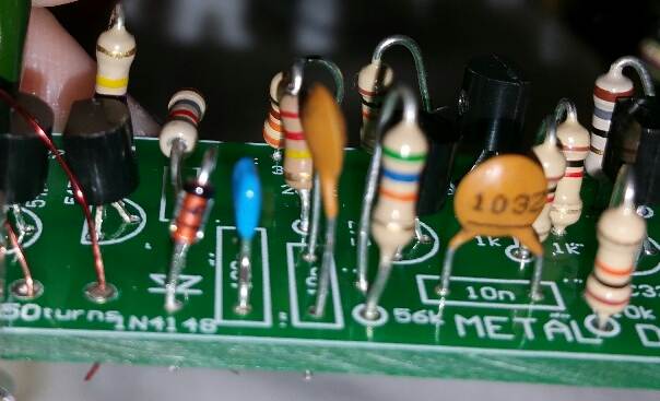
When fitting the components on
the Printed Circuit Board, use the overlay above to help locate the
correct holes.
When fitting the positive lead of the 9v battery snap, make sure you put
it through the large hole and solder it to the end of the switch as well
as the adjacent land.
The overlay on the PC board contains additional component
identification numbers that should not be on the board. The Chinese PCB
Manufacturer added all the overlay layers to the Top Silk layer and
this will be corrected in the next run.
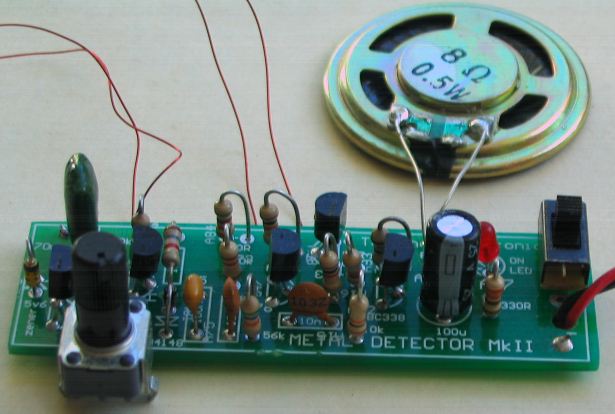
All the components fit on the PC board with the
coils and speaker on short leads
Here's a photo from a constructor. It shows how
NOT to fit the components.
The parts are not pushed onto the board before soldering. They are too
HIGH and look like "trees in a forest." The diode is around the wrong
way !!!
Look at the previous photo to see how neatly the components can be
fitted.
Here is another picture from a constructor.
He has used 1% resistors and it is impossible to work out
the value of each resistor and anything could be wrong.
I only supply 5% resistors in the kits . . . FOR A REASON.
It is easy to read the value and none of the resistors are
critical, so you use 1% ???
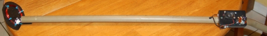
Here is the Metal Detector MkII project fitted
into a plastic box and
connected to a plastic pipe by Chris Hamel:
The diameter of the wire and the size of the coil is not critical
however our prototype uses 0.25mm enamelled wire wound on a 70mm diameter
former.
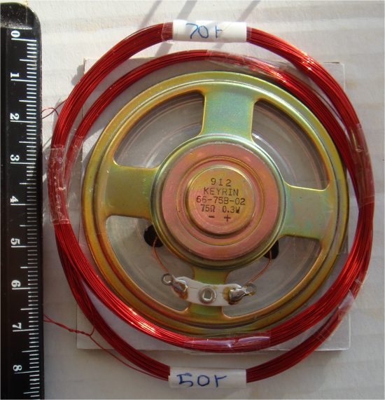
The 50 turn and 70 turn coils.
0.25mm wire 70mm diameter
Unwind the wire you have received and place it along the floor in a long
line so it can turn around on its axis when winding the coils. This will
prevent the wire twisting on-itself and kinking.
The two coils must be placed on top of each other and changing the number
of turns of the receiving coil does not alter the sensitivity of the
circuit.
The transmitting (oscillating) coil is 70 turns and the detecting coil is
50 turns.
The two coils must be placed together and covered with tape to keep them
together. But check the "Setting-Up" section before taping them
together.
Make sure the 70t coil is connected across the 47n capacitor
as the circuit will not work if the coils are exchanged. Don't worry
about the correct connection of the second coil as it can be turned over if
the circuit does not work.
The circuit will detect a small button cell about 7cm above the coil.
CHANGING THE
SHAPE AND SIZE OF THE COILS
The diameter of the coils can be
changed and the number of turns can be changed.
BUT you must start with the coils supplied in the kit.
One reader changed the coils to 100mm and the project did not work.
You MUST change the diameter or the number of turns a very small amount
and see if the coils have to be closer together or further apart to get
the circuit to work. You will have to adjust the pot to get the circuit
to work.
The 47n may also have to be changed to a higher or lower value.
The author has not done this and you will have to experiment on your own
in very small steps because if the circuit does not work, you will not
know how to bring it into operation.
Basically, the theory is: the larger diameter will produce deeper
penetration, but this also requires the coils to be supplied with more
energy and will require a higher supply voltage.
All these things can be tested, providing you do it in small steps.
You can add 10 turns to each coil and make sure you label each addition
by providing an exposed join (called a "tap" - tapping) with a tag. You
can use an alligator clip to select each tap and test the performance
against the original capability.
Once you have an improvement, send photos and circuit to us for
inclusion in this project.
SETTING-UP
Keep the two coils slightly apart and set the 500R pot to mid-position.
The output will produce a tone.
Slide the coils slightly closer together and turn the pot to stop the
tone. If the tone does not stop, turn one of the coils over.
If the pot has no range, remove one turn of the 50 turn coil. Keep
doing this until the two coils are touching and the pot has mid-range.
Tape the two coils together.
Adjust the pot until you get a very low-frequency clicking noise.
This is the most sensitivity setting.
DETECTION RANGE
The sensitivity of this design, using a 25mm-diameter coin, gave a clear
signal at 150mm.
Metal
Detector MkII |
|
1 - 18R resistor
all 0.25 watt |