|
MINI TRACKER |
Lets you find things, using an FM radio to pick up the beeps
See also: Beeper Bug Tracking Transmitter
|
You may need the LED Power Meter and/or Field Strength Meter MkI and Micro Battery Box Project |
Why track a pot-plant? Read on to find out . . .
![]()
Close-up of the MINI TRACKER
project
The layout of the board closely follows the circuit diagram.
This is a good policy as it makes testing and servicing easy.
|
|
Mini Tracker is the result of many requests for a tracking device and brings a
new world of tracking to your fingertips.
The circuit is very compact and consumes almost no power. It is small enough to
be hidden in anything you suspect will be lost or stolen.
By using a mercury switch or grasshopper, the bug can be “primed" for the time
when it is moved and you can track it with an FM radio.
A grasshopper is a switch that is ready to go off at any time. A piece of
plastic is placed between two switch contacts to keep them apart and connected
to cotton thread fixed to the floor. When the object is moved, the cotton pulls
the plastic out of the switch and the bug is turned ON.
One caller suffered the constant theft of pot plants from his verandah and
wanted a bug to track the thief.
Another had chemicals stolen from his warehouse and the cleaner was the prime
suspect. But to prove it is always difficult.
Something small enough to be placed in a case of detergent bottles was needed
and that's where we came into the picture.
The most notable theft occurred from a videotaping factory where packs of tapes
were leaving by the back door, some time during the night shift.
A bug like this would make an ideal detector to track down anything going
astray. By attaching it to the product under surveillance, you can follow its
removal and maybe turn up quite a few surprises.
The Mini Tracker transmits a very short burst of carrier which produces a
blank spot on the FM dial - commonly called “silence.” Normally, a lot of
background noise called “snow” is picked up by a radio when it is tuned to a
frequency between the stations. The change between silence and snow produces a
“click” or “beep” and this is the noise produced by the project. No actual
“beep-tone” is produced - just a change in signal quality. The carrier (or
silence) is emitted about twice a second.
HOW THE CIRCUIT WORKS
The circuit consists of two building blocks - both are oscillators. The first
operates at a very low rate (low frequency - about 2Hz) and the other operates at approx 90MHz.
The first is a square-wave oscillator with a very short “ON time,” while the
other is a sine-wave. The only thing they have in common is a “feedback
component,” to create and maintain oscillation. In all other respects they are
different.
The first block is a 2-transistor PULSE GENERATOR and the second is an
RF OSCILLATOR.
The first point we need to cover is the fact that the first "building block" is separated from the battery via a 1k resistor. This is very
important as the Pulse Generator takes a very high current when it is "active."
We say "high current" in relative terms as the whole circuit takes very little
average current as it is active for very short bursts. But the current is high
during the short bursts of operation and we need to check the current taken
during the bursts, to make sure it is as low as possible.
If the 1k resistor is removed, the Pulse Generator circuit would place a 220R
across the battery and this would put a heavy load on the battery during the
time when the RF oscillator is operating.
This would represent "wasted power" and decrease rail voltage during the time
when we need maximum output. To prevent this, we have separated the Pulse
Generator circuit from the RF Oscillator with a 1k resistor.
To give the Pulse Generator its own separate "Power Supply" we have added a 22u
electrolytic.
The diagram below shows the separate "Power Supply" for the Pulse Generator.
![]()
The 22u charges via the 1k resistor and when the Pulse Generator circuit
requires its "high current," the 22u delivers the energy. This feature is
called STAGE SEPARATION or BLOCK ISOLATION and separates the power requirements
of a "building block" from the rest of the circuit.
The 1k and 22u electrolytic have been connected exactly like a "delay circuit"
but they are not used as a delay feature in this arrangement.
The 1k slowly charges (in relative terms) the 22u and the Pulse Circuit draws a
high amount of energy from the 22u for a very short period of time. The voltage
across the 22u drops slightly and when the Pulse circuit switches "off," the
22u charges to maximum voltage.
In the diagram below, we have removed all unnecessary components and shown only
the Pulse Generator circuit. The output of the Pulse Generator is LOW
for short bursts and this turns the RF Oscillator ON. When the output of
the pulse Generator is HIGH, the RF oscillator is OFF.
During this time the circuit consumes very little current (only a few microamp).
![]()
The Pulse Generator circuit has a "time delay" made up of a 10u and
220R/220k resistors in series.
The 220R has very little effect on the charging but the 220k creates the long
charge-time. This is shown in the diagram below:
![]()
The important point on the time delay circuit is the "pick-off" point or
"detection" point - shown in the diagram above as point "A.". This point is being monitored by the rest of
the circuit (the base of the PNP transistor) and when a particular voltage is reached, the circuit changes
state.
In our case, the voltage at point "A" is initially HIGH and when the
voltage falls about 0.75v below rail voltage, the BC 557 transistor turns ON.
The BC 557 is a PNP transistor and it operates as a "mirror" to an NPN transistor,
that's why the voltage on the base must be lower than rail voltage for
it to turn ON.
When the power is turned on, the 10u is uncharged and point "A" is very close
to rail voltage.
As the 10u charges, the voltage at point "A" reduces. The 10u is actually
charging in reverse and although this is not advisable, an electrolytic can be
changed slightly in reverse without any damage. As soon as the voltage on the
base of the BC557 is 0.7v lower than rail voltage, the transistor turns ON and
this turns on the BC 547, via the 1k resistor.
The voltage on the collector of the BC 547 is reduced by the action of the
transistor turning ON and this causes a very high current to flow into the 10u
to charge it in the forward direction.
This charging current turns on both transistors fully and the output of the
Pulse Generator is LOW.
The 10u charges very quickly and very soon the charging current reduces to a
point where the BC 557 cannot be turned on as a "saturated transistor." The
transistor turns off slightly and this action turns off the BC 547.
The voltage on the collector of the BC 547 rises and this turns off the BC
557. The BC 547 also turns off.
The 10u discharges through the 220k and this creates the long "off-time."
The PULSE GENERATOR is a
special type of oscillator in which the “OFF time” is very long and the “ON
time” is very short, with the output changing very quickly from one state to
the other.
This gives the circuit the characteristic name "Square Wave Oscillator."
A square wave oscillator does not always have an equal "on" and "off" time. It
is the action of the output moving very quickly from one state to the other
that gives it the name SQUARE WAVE OSCILLATOR.
The animation below shows how the electrolytic charges and brings the two
transistors into the circuit by turning them ON.
![]()
THE PULSE GENERATOR CIRCUIT IN
OPERATION
The operation of the Pulse Generator circuit is more complex than first
meets the eye. I don't expect you to understand its operation via this brief
discussion. It will be covered in more detail in the BEC Course. It is
sufficient to see the charging of the electrolytic controls the timing of the
circuit and the electrolytic appears to jump from above the BC 557 to
below it, as it turns the transistor on and off.
If you can "see" this effect in operation, you are on your way to understanding
how the circuit works.
When the output of the Pulse Generator is LOW, the RF oscillator produces a
carrier and this is picked up on an FM radio as "silence."
When the RF oscillator is not operating, the radio picks up background noise,
commonly called "white noise."
The difference between these two creates the "beeps." The circuit does
not actually produce a "beep."
The circuit takes almost no current between beeps and the duty cycle of the
“beep” is only a few percent.
This makes the project very economical on batteries and you should get
many hours of operation from two or three button cells.
The RF oscillator is turned ON when the Pulse Generator circuit is LOW and the
330R emitter resistor is effectively connected to the negative rail, via the
collector-emitter junction of the Pulse Generator. The RF transistor is also
turned on via the 47k base bias resistor and current flows though the collector
circuit consisting of a 5 turn coil and 39p.
The capacitor begins to charge as the coil presents a blockage to the voltage
at this early stage of the cycle.
As the capacitor charges, the voltage across it is detected by the coil.
Gradually the coil will allow current to flow through the windings and produce
magnetic flux. This all happens in less than a microsecond, however there are
specific times for each of the operations and this determines the frequency of
the circuit. The voltage on the collector of the transistor changes and this
alteration is passed to the emitter via a 10p capacitor. The voltage on the
emitter is modified and the transistor is tuned on. There are two ways of
turning a transistor on and off. One is to raise and lower the voltage on the
base while keeping the emitter fixed. The other is to raise and lower the
voltage on the emitter, while keeping the base fixed.
The base is effectively kept rigid by the presence of the 1n capacitor and the
sinewave signal produced by the parallel oscillatory circuit, turns the
transistor on and off.
There is a lot more that could be discussed about the operation of the circuit
but it becomes too technical at the moment.
One thing that can be mentioned is this: when the magnetic flux collapses from
the coil, it produces a voltage in the OPPOSITE DIRECTION and the amplitude can
be larger than the supply voltage. This is why the voltage on the collector is
higher than the supply voltage.
The antenna is connected to the oscillatory circuit and since the frequency is
very high, current flows in and out of the wire.
This current produces an electromagnetic wave from the antenna, called a
signal. (It can also be called RADIATION or ELECTROMAGNETIC RADIATION).
The actual frequency of the RF oscillator is determined by a number of factors
but the main influence is the value of the capacitor and inductor in the
oscillator circuit. The amazing feature of this circuit is the fact that it is
capable of producing a waveform that is larger than the applied voltage. This
is called the “Q” or “Quality factor” of the circuit.
A coil and capacitor connected in parallel is called a TUNED CIRCUIT and
because it stores energy and releases it similar to a tank holding water, the
circuit is also called a TANK CIRCUIT. (Also called a PARALLEL TUNED CIRCUIT).
CONSTRUCTION
All parts fit onto a small PC board and by using miniature standard components;
the size is kept to a minimum.
|
Keep this in mind when collecting the parts. If you use old-style items, they will not fit. The safest way is to buy a kit. All the components in a kit have been selected for their size and reliability and these decisions would take a whole page to relate. For instance, the ceramic capacitors are NPO types for stability and the resistors are 1/4watt types.
![]()
All the parts must be kept close to the board when soldering so they are
not too high as they may upset the frequency and operation of the circuit.
All resistors stand-up on the board and the easiest way to carry out
construction is to fit a few components at a time and cut the leads after
soldering. This will allow you to add more components without anything getting
in the way. Never cut the leads before soldering. One project came in for
repair. One of the leads of a component had been cut too close to the board and
it was not making a connection. By moving each component, the faulty joint was
located, but it was a lot of fiddly work!
The overlay makes it easy to see where the parts go and the only two things you
have to be careful with are the BC 547 transistors and the BC 557, and the
polarity of the electrolytics.
Don't forget to tin the ends of the oscillator coil to remove the enamel before
fitting it to the board. This can be done by either applying a generous amount
of solder to the iron and using the solder to heat the wire until the enamel
bubbles off, or removing it by scraping with a knife or blade.
To power the Mini Tracker, you can use two or three button cells or AAA cells.
The size of the cells is not a critical factor but we found the larger cells
provide a better ground plane and improve the output.
We have designed a Micro Battery Box to hold 3 “watch cells” and the article
is also on the site.
As the circuit turns on in very short bursts, the cells will last much longer
than our audio FM transmitters which draw a higher constant current.
Finally, the antenna wire is soldered to the last remaining hole on the board
and the project is ready for testing.
OPTIONS
Button cells can be fitted into a micro battery box made from pieces of blank PC
board. 3 cells will produce a voltage of about 3.6 - 4.5v, depending on the
type of cell. You can also use lithium cells, which are 3v each. By using 2
cells (6v) the output will increase by more than 300% and this will give
considerably better range. If you intend to use lithium cells, a holder will be
needed.
The circuit has been designed to operate at 90MHz, and if required to operate
at the high end of the band (108MHz), the 39p could be changed to 33p. Our
tests showed the output at this frequency to be less than at 90MHz.
The length of the aerial can be cut to meet your requirements, and the actual
length is not very critical.
TESTING
With the power switched off, connect a multimeter across the switch terminals
and you will see the needle jump very briefly to indicate the circuit is
operating.
You will not be able to work out the average current as the duty cycle is too
short, but you can see it is microscopic by the minûte movement of the needle.
Next, test the current consumption and the frequency of operation. Connect a
short length of tinned copper wire between the collector and emitter terminals
of the BC 547 in the pulse circuit.
This will turn on the RF stage fully and you will be able to get a reading of
about 5-8mA. This shows everything is operating.
While the link is still in place, switch the unit ON. Set up the antenna as it
will be on the glider or pot plant etc.
Tune an FM radio between 89MHz and 108MHz and expand the turns of the coil to
raise the frequency, until the beep is detected. Keep the radio away from the
transmitter to prevent picking up harmonics (side-tones). Remove the link and
the project is ready for installation.
IF IT DOESN'T WORK
If the “beep” doesn't work, you will have to determine which block is not
functioning by comparing with the following symptoms:
If the circuit gives out a constant blank spot on the radio, the pulse
generator section will be faulty. If no signal is picked up at all, the RF
section may be faulty.
Firstly check the current consumption. If the needle “jumps” but no RF is
detected, the oscillator may be off the FM band. Separating the turns of the
coil will increase the frequency and maybe bring it onto the band.
You can use the
Field Strength Meter or
Peaker (LED Power Meter) to find out if RF is
being emitted. These two projects have been designed by Talking Electronics and
can be found in our price-list of kits.
If RF is detected, you should check the value of components around the RF
section and the number of turns on the coil.
The spacing of the turns is also critical, as is the diameter of the coil. The
kit comes with a pre-wound coil (5 turns @ 3mm dia) and the holes on the board
give some idea of the spacing of the turns.
Shorting between the collector and emitter of the BC 547 in the pulse generator
circuit will cause the carrier to be emitted continually and if a blank spot on
the dial is detected, but no beep, you should check the voltage on the
collector of the pulse generator section. A CRO will be the easiest way to see
the output. The needle of an analogue multimeter will move very slightly to
show the circuit is operating.
If RF is not detected, the fault will lie in the RF stage.
The components making up this are the 47k, 39p, 5 turn coil, BC 547 transistor,
10p, 5p6, 1n, 330R and the 22n across the battery.
The operation of the RF section of the circuit has a lot to do with two things:
capacitance and voltage.
The capacitance of the circuit is mainly determined by the value of the
components but the presence of your hand will also have a small effect. For
instance, touching the batteries will shift the frequency slightly and you will
think the circuit has stopped working.
Once the project is placed in position, it must not be touched. The circuit is
very stable and will maintain the same output frequency - providing it is not
touched.
During the end of the life of the batteries, the supply voltage will fall and
the frequency will shift slightly. These are the only two limitations of a
simple circuit such as this.
Once you get the project working you can change things but keep everything
compact at the start.
TRACKING
The Mini Tracker can be tracked with an FM radio.
It is not possible to determine the distance between the transmitter and the radio by the loudness of the beep but a very clever way to track the beeper is as follows:
Most FM radios have a telescopic antenna and by extending the antenna, the sensitivity of the radio can be increased.
In addition, the antenna can be rotated (by moving the radio around) and pointed so that the reception is improved.
By simply pointing the antenna in the direction of the transmitter, the pick-up will be the least and if the level is down to "snow," the beep will difficult to detect.
This is the aim of the exercise.
Once you can get a situation where the beep can be switched on and off, (heard and barely-heard), you can start to locate the transmitter. As you get closer, you may have to reduce the length of the antenna.
When you get very close to the transmitter a problem arises. It is very difficult to "home-in" and pin-point it in a room as you do not have any means of detecting "signal strength."
This is where a "signal strength meter" or "bug detector" comes in. A bug detector is specially designed with an indicator to show the strength of the signal and you can "home-in" and locate its position, especially when it is hidden.
DIRECTION FINDING ANTENNA - DIRECTIONAL ANTENNA - RDF (Radio Direction Finding)
A more-complex set-up is to add a directional antenna. This turns the radio into RDF. This consists of an antenna in the form of an "H" as shown in the following pictures:
 |
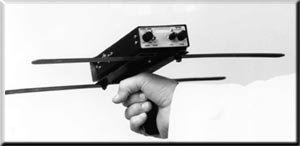 |
As the antenna is rotated, the signal from the transmitter is reduced to
zero (or near zero) and this lets you know the signal is coming from the side,
as shown in the diagram at the bottom of the page.
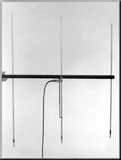
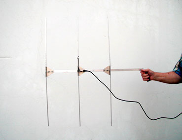
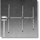
There are variations of the "H" antenna and none of these are improvements of
the original design. They are more expensive to construct and seem to be more
commercially viable, as everyone likes complicated things:
 |
 |
|
|
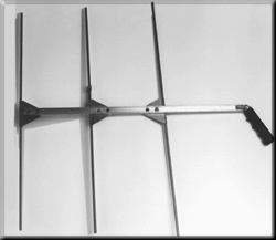
The "H" design is the best concept as it is the cheapest, simplest and most
effective.
It works like this:
When the active element of the antenna faces the signal, the reception is a
maximum. When the antenna is rotated 180 degrees, the reception is less as the
signal has to pass the reflector element and this element is effectively
"earth." When
the antenna is rotated 90 degrees to the signal, the reception is almost zero.
From these three facts you can work out the direction of the signal.
The antenna is designed to have a better pick-up from the front than the back.
Ideally, the receiver should have a signal strength meter, otherwise use the
concept of detecting a maximum signal in the front ( or forward) direction and
a lower signal when the antenna is rotated 180 degrees.
This can be done by rotating the antenna and taking it high in the air and low to
the ground to alter the pick-up.
It will only take a short time to work out what to do.
CONNECTING TO A RADIO
The simplest way to connect the antenna to a radio is to connect the centre lead of a length of coax to
the active element. The outer screening does not have to be connected.
If the antenna is a more-complex design, the centre pole will be metal and
become part of the "earthy" portion of the antenna. The screen of the coax can
then be connected to the "earthy" part of the antenna.
You don't need a high-gain antenna. It can be built from two coat-hangers and a length of wood or dowel.
Put one together and see how you go at tracking.
Go to Micro Battery Box Project