|
5v
SOLAR POWER
SUPPLY |
This
project uses a 1.2v cell and solar
panel from a
Solar Light
circuit 1.
If you have bought a Solar Garden Light
similar to Circuit 2 - click HERE
The Solar Garden Light
can be bought for less than $5.00!!
Kits for the 5v Solar Power Supply can be bought from Talking
Electronics.
These are the pages on SOLAR CHARGERS:
1.
Solar Charger
2. Solar Light
3.
5v
Solar Power Supply - Circuit 1 - this page
4.
5v
Solar Power Supply - Circuit 2
5. Solar Charger - Push Pull circuit
6. Solar 5v Supply using 2 Garden
Lights - this page
See also
an article on hand-cranked
generator
![]()
This project uses the 1.2v rechargeable battery and solar panel from a
Solar Garden Light. These lights can be bought for less than
$5.00 in most $2.00 shops or similar shops that sell general
household items.
We are also using the housing for this project as we could not buy the
case, battery and panel for $5.00 in an electronics shop.
It is incredible that a solar panel, rechargeable battery and plastic
housing can be bought for less than $5.00!
We have already described the operation of the
Solar Circuit, but
unfortunately it cannot be used to generate a voltage higher than about
4v, so a new design had to be created. The circuit we have designed is
shown above and provides a regulated 5v output @ 10mA. If a higher
current is drawn, the output voltage will drop. At 15mA, the output voltage
drops to 4v.
This supply has been specially designed for a microcontroller
project, but it will also work for circuits such as amplifiers, FM
transmitters etc.
HOW THE
CIRCUIT WORKS
The
circuit consists of an oscillator transistor and a regulator
transistor.
The solar panel charges the battery when sunlight is bright enough to
produce a voltage above 1.9v. A diode is required between the panel and
the battery as it leaks about 1mA from the battery when it is not
illuminated.
The regulator transistor is designed to limit the output voltage to 5v.
This voltage will be maintained over the capability of the circuit,
which is about 10mA.
The oscillator transistor must be a
high-current type as is is turned on for a very short period of time to
saturate the core of the transformer.
This energy is then released as a high-voltage pulse.
These pulses are then passed to the electrolytic and appear as a 5v
supply with a capability of about 10mA. If the current is increased to
15mA, the voltage drops to about 4v.
The transformer is wired so that it gives POSITIVE feedback.
The transistor turns on via the 1k resistor and this produces expanding
flux in the core.
The flux cuts the turns of the secondary winding and produces a voltage that
ADDS to the turn on voltage and the transistor is turned on MORE. The
transistor gets fully turned ON and the current through the primary
becomes a maximum. The core becomes saturated and although the flux is a
maximum, it is not expanding flux and thus the secondary produces no
voltage (only the voltage and current supplied by the battery).
The voltage and current into the base of the transistor is reduced and
this reduces the current through the primary.
The flux now begins to collapse and this produces a voltage in the
secondary of an opposite polarity.
This turns the transistor OFF and the magnetic flux collapses quickly
and produces a high voltage.
This voltage is passed through the diode and charges the electrolytic.
The circuit operates at approx 50kHz and the pulses quickly charge the
electrolytic.
The 15k resistor has a 3k3 "trimmer" resistor to enable you to adjust the output
to exactly 5v or slightly above 5v. Microcontrollers will work up to
5.5v but some will freeze at 5.6v, so be careful.
The output voltage is
monitored at the join of the 15k resistor (and 3k3) and the 2k2 resistor. The
voltage at this point is exactly 0.63v (630mV) and at this voltage the
regulator transistor turns ON and robs the oscillator transistor with
"turn-on" voltage.
When a load is placed on the output of the circuit, the voltage across
the electrolytic drops and the regulator turns off slightly. This
allows the oscillator transistor to operate "harder" and send pulses of energy to
the electrolytic to charge it. If the load is removed, the current
consumption for the circuit is about 3.5mA. This is the quiescent current for
the circuit.
The output current is limited as each mA requires about 5mA from the battery.
At 15mA output, the current required from the battery is about 75mA.
That's why we need a high-current capability transistor for the
oscillator.
A BC 547 transistor will not work, as it is not
capable of passing a high current.
The solar panel will deliver about 10 - 15mA on bright sunlight, so any
load on the output must be as small as possible.
An example is data logging, where the micro is active for short periods of time,
then goes into "sleep" mode.
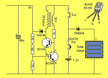
AUTOMATIC
The
circuit can be made automatic by adding a 1k
resistor and diode:
Automatic Solar Power Supply Circuit
The oscillator will turn off when the output from the
solar panel is above 1.3v and although the circuit does not shut down to
zero current, it consumes about 3 mA, while the shut-off circuit takes
about 1mA.
On a bright day, the solar panel delivers 20mA to the battery, so the
overall net charging current is about 15mA max.
This means any data logging circuit or transmitter connected to the
supply will only work at night.
To go over the purpose of the automatic section again:
The automatic components turn off the 5v section so the battery can
charge and store enough energy to operate a transmitter during the night
hours, when it will be needed.
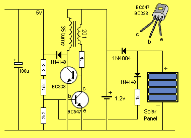
If a very small current is required by a load such as a microcontroller,
the following components can be used to bias the oscillator - as
outlined by contributor James Moxham:
Low Current Power
Supply Circuit
ASSEMBLY
The only
component that has to be made is the fly-back transformer.
The core of a 10mH choke is used and re-wound with two windings.
Remove the fine winding and keep for another project.
The core is now bare and ready.
The first winding is 35 turns and the ends are connected to the pins at
the end of the core. The other winding is 20 turns and has flying leads
connected to two holes on the PC board. The 20 turn winding must be
connected around a special way to provide a positive voltage to the base
of the oscillator transistor. The operation of the circuit will depend
on the direction of one winding relative to the other.
Rather than remember which way each winding has been wound, we simply
connect the 20-turn winding to the board, via the flying leads, and if the circuit does not
oscillate, we swap them over.
The diameter of the
wire used for the transformer has been worked out so that it completely fills the
bobbin. This gives the maximum milliwatt output. That's why the
old fine wire cannot be used.
Mount the components on the small PC board that comes with the kit or on
a piece of matrix board.
Two switches have been used in the circuit to allow you to charge the
battery while keeping the project off.
IF IT DOESN'T WORK
If the circuit does not work, the first thing to do is reverse the
flying leads of the transformer.
If this does not solve the problem measure the current taken by the
circuit. If it is HIGH, you have a failed (jammed) oscillator section or
the output
of the circuit may be shorted. If the consumption is LOW, the oscillator transistor may not be
fitted correctly or the diode feeding the electrolytic may be around the wrong way.
Make sure the enamel is scraped off the ends of windings before
soldering.
If the output voltage is above 5v, the regulator transistor is not
working. Make sure the resistors are the correct value. Measure the
voltage at the join of the resistors with a high impedance meter so no
load is added to the circuit as this will upset the measurement.
If you have added the automatic section, make sure the solar panel is
not receiving any sunlight as this will turn the circuit off.
In future articles we will present a
microcontroller project and an FM transmitter that uses this solar power supply.
Keep returning as the links will be added to the top of this page.
| |
|
Colin Mitchell
23/12/2005