|
SOLAR GARDEN LIGHT |
How a Solar Garden
Light works
Two different
circuits and how they work
Both circuits can be
converted to 5v regulated output.
See:
Power Supply 5v
Solar
No kits are available for
this discussion.
The complete Garden Light
can be bought for less than $5.00!!
These are the pages on SOLAR CHARGERS:
1.
Solar Charger
2. Solar Light - this page
3.
5v
Solar
Power Supply
- Circuit 1
4.
5v
Solar Power Supply
- Circuit 2
5. Solar Charger - Push Pull circuit
6. Solar 5v Supply using 2 Garden
Lights
See also
an article on hand-cranked
generator
![]()
Circuit 1
Both Solar
Garden Light circuits in this article perform 2 functions:
1.
They charge a battery and
2. Turn on a high-bright white (or yellow) LED at dusk and off during daylight hours.
The two circuits are completely different in design and we will see how
different designers tackle the same problem.
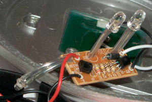
Firstly we will discuss the circuit above. It is called Circuit 1.
Here's the clever part: The circuit doesn't deliver a DC voltage to
the LED but a high-frequency pulse. This creates the same brightness
from the LED (as a constant DC voltage)
while needing less than 50% of the energy. It also allows a single cell
to be used.
Also, the circuit does not have a dropper resistor for the LED and this
further increases the efficiency.
The third clever idea is the use of a single rechargeable cell - even though the white LED requires 2.3v.
And the final clever feature is the use of 4 solar cells to charge the
rechargeable cell.
By using a single cell, it is only necessary for the solar panel to
produce a voltage above
1.2v for charging to occur. This can be achieved with 3 cells, but if an additional cell is
included, the voltage from the panel will rise above 1.2v when the day is
not very sunny and thus the battery will be charged almost all the time during the day.
On a very dull day the charge current will be as low as 1mA and increase to over
9mA under very bright sunlight.
The solar panel also performs another function.
It turns the LED on and off.
As soon as the voltage from the panel rises above 0.7v, the circuit detects this
and turns off the oscillator. This means energy from the battery is not
used during the day.
The first transistor is called a "cut-off transistor." It turns off the
oscillator section by robbing the base of "turn-on voltage."
When the LED is illuminated, the circuit consumes 10mA, and if you
work out the number of night-hours to daylight hours, you will see the
LED will illuminate for about 6 hours. This is sufficient for most
applications.
CURRENT LIMIT RESISTOR
Although a current-limiting resistor between a solar
panel and a battery is technically needed, it is not necessary if the battery
will not be overcharged. In our case, the solar cells will not
overcharge the battery.
THE SOLAR CELL
The SOLAR CELL actually consists of a number of cells as each
cell only generates about 0.5v to 0.6v.
The Solar Cell in our model consists of 4 cells and produces approx 2v
with bright sunlight.
The short-circuit current produced is about 30mA and although this is
not the correct way to determine the current capability of the cell, it
has been given to help you select a suitable cell (or set of cells). The
current will drop considerably when the solar cell is connected to a
1.2v battery via a diode and our project delivered 8mA.
HOW THE
CIRCUIT WORKS
The
circuit consists of two stages. The first stage is a "switch" or cut-off
device. It detects
a voltage above 0.7v from the solar panel and the resistance between its
collector-emitter terminals reduces to a very small value.
The 10k resistor allows the voltage on the solar panel to rise above
0.7v during bright sunlight, while the 100k discharges the 100p when the
voltage is very low and the capacitor holds a charge to keep the
transistor turned on when the voltage is "high".
When the resistance between the collector-emitter terminals of the first
transistor is low, it is turned ON, and
the second transistor does not get enough voltage on its base for it to
operate as an oscillator.
The function of each component
The purpose of the first transistor is to keep the second stage OFF when
the solar cell detects sunlight.
This allows the energy from the solar cell to be passed to the
rechargeable battery.
The second transistor is an oscillator.
To see how it works we remove the first transistor.
The second transistor works by itself. The components in the circuit
are: the transistor, the two chokes, the 6k8 resistor, the 1n2 capacitor
and the LED.
An oscillator needs feedback called POSITIVE
FEEDBACK. Positive feedback creates noise or "oscillation" in a
correctly designed circuit.
An oscillator must be self-starting and the circuit in this project starts
to oscillate by detecting a
voltage on the base.
The transistor amplifies this and a larger waveform (larger voltage-
change) appears on the
collector. This is then passed to the base so that oscillation
continues.
For oscillation to occur, the
feedback signal must be delayed by a small amount of time.
This small amount of time determines the frequency and the feedback
signal has another feature (or characteristic). It is presented to the
base with an opposite polarity to that on the collector. To be more
precise, the voltage must be moving in the opposite direction. This is
called "180° out of phase."
This is
achieved by the inductor and the 1n2 capacitor. We all know a capacitor
creates time to
charge, but an inductor also has a delay-factor.
A resistor does not have a delay-factor, as a voltage at one end of it will appear immediately at the other end, so we can explain the
delay-time for an inductor by connecting an inductor in series with a
resistor.
There have been many technical descriptions on how an inductor delays a
signal, but never a simplified description.
Here is a simple way to understand how an inductor creates a delay.
In the following animation, you will see how the signal (the voltage) is
delayed:
The main feature of this animation is to
show an inductor effectively GROWS when an applied voltage is delivered
to it by producing a back-voltage and thus the voltage at its other end
does not change until the core is saturated. This understanding is most important in the circuit we
are discussing as the top lead of the inductor is taken from a
low-voltage to a high voltage by the action of the transistor when it is turning
ON
and OFF. As the top lead is taken from one voltage-level to the other,
the lead connected to the capacitor does not see this rapid change, but
continues in the cyclic process of charging and discharging the
capacitor. That's why this circuit is so difficult to understand.
Let's look at the characteristic is the inductor in more detail:
The voltage applied to the inductor starts at zero. As it rises, the turns of wire on
it produce magnetic flux that cuts the other turns and
this action produces a voltage that opposes the incoming voltage, and a surprising thing happens.
The resulting forward voltage is very small and this causes very little current
to flow.
Thus the voltage across the resistor does not
change. This is similar to saying the waveform does not appear at the other end of the inductor. As the waveform rises further,
(the applied voltage increases) the core of the inductor becomes saturated.
At this point it cannot produce any more flux. The opposing voltage
(produced by the expanding flux) is reduced and this allows a higher
current to flow. This causes an increase in the voltage across
the resistor. If the resistor is replaced by a capacitor, the capacitor
would see a delay before it starts to charge. When the inductor is
combined with a capacitor, the two components form a circuit that delays the signal to the base
by 180° and the circuit oscillates at a frequency of about
500kHz.
The operation of this circuit can be found in text books under
the heading Hartley Oscillator.
But it's a bit more complicated than first meets the eye as the inductor
in the positive rail assists in the generation of the waveform.
Thus the circuit is beyond the scope of our discussion.
The only two things you need to understand are:
The in-rush of current for a capacitor and an
inductor.
When a capacitor is connected to a voltage-source, the initial in-rush
of current is high and it gradually decreases to zero as it
charges.
When an inductor is connected to a supply, the initial in-rush of
current is small and gradually increases.
The waveforms across the capacitor and LED are shown in the following
diagrams:
The other feature we can discuss is the
function of the top 0.47mH inductor.
When the transistor turns off, the magnetic flux in collapses and it produces a high voltage.
This voltage is high enough to illuminate the LED and the graph shows
that when the LED is removed from the circuit, the voltage produced by
the inductor has a peak of about 3.5v. The area under the peak represents energy and
this is absorbed by the LED to produce light. The LED also reduces the
peak to 2.3v as this is the maximum voltage (or characteristic voltage)
of a white, super-bright LED.
Make an effort to buy a Solar Garden Light from a $2 shop and pull it
apart, just to see how it works.
If you have a CRO, you will be able to view the waveform on the 1n2
capacitor and across the LED.
The waveform across the capacitor is an incredible 10v p-p with part of
the waveform going negative by 4v. During the negative excursion, the transistor is turned off and
the magnetic flux produced by the current-flow in the top inductor
collapses very quickly and produces a high voltage that has an opposite
polarity to the energising voltage.
Now we will cover circuit 2:
Solar Garden Light-2 consists of three transistors. The first two
transistors form a positive-feedback amplifier and the third transistor
is a common-emitter amplifier.
This voltage is passed to the LED and light is produced.
The short pulses of energy delivered to the LED occupy about 20% of the
total time but the energy they deliver produces a light-output equal to a
constant DC voltage. By delivering short pulses, only about
30% of the energy is needed to produce the same illumination as a
constant voltage.
The circuit only needs the first two transistors to create an
oscillator.
The circuit turns on when the photo resistor fails to detect light and
its resistance effectively goes very high. This allows the 47k base
resistor to turn on the transistor. The voltage rises on the base as the
100n charges and the transistor turns on.
This action turns on the BC 557 transistor and the voltage on the
collector rises.
This increases the current into the base of the first transistor via the
100k resistor and the two transistors would stay in this state if it
were not for the 330p capacitor.
The 330p also pulls the base of the BC 557 towards the 0v rail and this
assists in turning on the BC 557.
This occurs when the the first two transistors turn on as the
emitter-follower third transistor is also turned on during this action.
The 330p is pulled low during this action and it quickly charges. When
it becomes charged, the "turn-on" current for the BC 557 is
reduced and it turns off
slightly.
This action reduces the current through the 100k feed-back
resistor and the first two transistors begin to turn off.
The third transistor is also turned off and the current flowing through
the inductor is reduced. This causes the magnetic flux to collapse and
produce a voltage in the opposite direction.
In the first instance, the voltage on the top of the inductor was
more-positive than the voltage on the lead connected to the collector.
When the current is reduced, the voltage collapses and produces a
voltage that is negative at the top lead and positive at the lead
connected to the collector.
This is exactly the same as connecting a battery to the positive rail of
the project with its negative on the top rail and positive to the
collector.
This produces a very high voltage on the collector of the transistor and
is passed to the base of the BC 557 via the 330p. The BC 557 is
effectively turned off completely. The result is the
first two transistor are fully turned off and the third transistor is
also fully tuned off.
This is exactly the same as removing the third transistor from the
circuit.
The inductor produces a voltage (in the form of a spike) that is higher
than 2.1v to illuminate the high-bright yellow LED - in fact it is much
higher but the LED converts this energy to light.
You cannot measure this voltage with a multimeter as the voltage is
produced in the form of spikes.
If you remove the LED, a CRO will show the spikes are higher than
40v.
This makes the circuit ideal for converting to a 5v supply as shown in
our other article:
Power Supply 5v Solar.
An email from a reader
asks about the inductors:
http://www.prc68.com/I/EOG.shtml
If you have a circuit as shown in the following
photo, that is is powered by 3 AA cells, the circuit does not need any
inductors as the 4.5v is sufficient to illuminate white LEDs.
CONCLUSION
Both circuits are much more complex than you would expect, in such a
simple product. But that's the miracle of electronics.
You will see the same level of sophistication in many products, such as
talking birthday cards, toys, LED torches, etc.
There may be other circuits in these Garden Lights as the author has
seen at least 10 different types.
The main thing to look for is the size of the solar panel.
The solar panel in Circuit 1 produced a current of 25mA with full
sunlight. The current produced by the solar panel in circuit 2 was 50mA.
It had twice the amount of active surface.
This is just another product that costs less than buying the individual parts from an
electronics store.
Now you can see why the hobby of electronics is dying, just when
electronics is e-x-p-a-n-d-i-n-g! But that's no reason to give up.
There is still an enormous demand for new ideas and gadgets.
Next time you see a Garden Light glowing at night in a garden, you will appreciate the
amount of work that has gone into the design of the circuit.
Colin Mitchell
8/12/2007