![]()
WIND-UP TORCH/RADIO
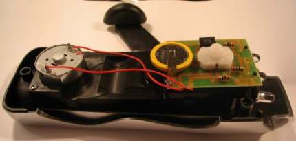
Now we come to a very nifty product: A wind-up radio and torch. It consists of an FM radio and a 3-LED torch.
The comment in the advert says: 1 minute of winding will light the torch for more than 10 minutes. This is incorrect. Let's find out why:

The interesting
components in the product are the hand-cranked generator and 3.6v Li Ion 450mAhr
battery.
This battery is just 25mm diameter and 5mm thick. If you remember the
old Ni-Cad AA cells, they were about 450mAhr capacity and had an output
voltage of 1.2v. This cell is equal to 3 of the old Ni-Cad cells!
3 Ni-Cad cells supplying
3.6v 300mAhr
But the purpose of this discussion is to point out a technical mistake
with the charging circuit.
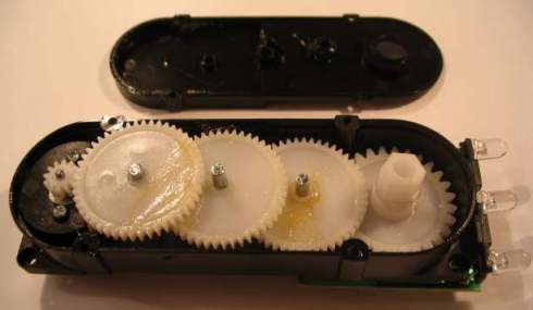
The generator consists of a 4v motor connected to a compound gearbox
with a crank-handle.
A compound gearbox is a gearbox with a "train of gears" (a set of gears)
in which the gears are placed on shafts so that the "drive" goes from
one shaft to the other and then back onto the first shaft. This saves
space and makes a very compact gearbox. See photo below:
The Compound Gearbox
When the handle is turned fairly quickly, the output of the motor
produces a
maximum of 5.5v and has a current under short-circuit conditions of
about 400mA.
You would think this is sufficient to charge a 3.6v cell, but it isn't.
The generator is connected to a bridge rectifier.
This has been done so the cell will charge, no matter which way the
handle is turned.
But the bridge takes 1.2v from the generated voltage, leaving only 4v.
When tested, the cell is receiving only 30mA, charging current!
The torch takes 45mA and the radio takes up to 90mA on full volume.
The instructions on the pack says 1 minute of winding will provide up to
30 minutes of operation.
This is clearly untrue and the only reason it is not immediately evident
is due to the fact that the 3.6v cell is fully charged when the unit is
sold.
How do we fix the problem?
There are two ways to solve the situation. The motor can be re-wound
with more turns on each leg of the armature (it is a 3-pole motor) or a
voltage-increasing circuit can be added.
We tried two different voltage-increasing circuits. An electrolytic to
increase the voltage (in a charge-pump arrangement) and a flyback arrangement using a transistor and
inductor.
Both circuits only allowed 50mA to be delivered to the cell and we
considered we could improve on this by re-winding the armature.
From the photo below, you can see the armature is not fully filled by
the original winding and this gives us an opportunity to add more turns. If the
armature was already filled, we would have to remove the windings and
use a finer gauge of wire so more turns could be put on each leg.
The "start" winding on each leg is soldered to the previous segment on the
commutator and the end of the winding is soldered to the segment
adjacent to the leg. The actual position of these segments depends on
the position of the brushes so we cannot say they will always be aligned
with a leg.
By simply removing the end of the winding and joining our new wire to
it, we can add as many turns as possible. In our case 100 turns were
added and the end of the wire was soldered to the commutator segment.
The disassembled motor (generator)
The following photo shows 100 turns added to each leg of the armature:
The 100 turns added to each leg
Only 100 turns could be added otherwise the
turns touched the casing of the motor when the armature was replaced and this prevented it from turning.
When the motor was re-installed, the output voltage increased from 5.5v, to about 10v and the short-circuit current changed from
about 400mA to 300mA.
A single diode
was added to the positive line to prevent the Li-Ion cell from driving the motor
in the opposite direction
when the handle was not being turned and a green LED with 2k2 resistor shows when the generator is turning
in the correct direction to charge the battery. The diagram below shows
the circuit:
The diode and LED connected
to the generator
The generator now delivered 100mA to the
cell and this was an increase of more than 50mA over any of the other
arrangements.
The main reason why only 100mA is delivered during the charging is due
to the floating voltage generated by the Li Ion cell. It produces a
voltage of 4.2v when charging.
After the cell is charged, and a load applied, the voltage gradually
drops to 3.6v and this is why the cell is rated at 3.6v.
As a side issue, 3 Ni-cad cells produce a floating voltage of about
4.15v when being charged, so they pose the same problem.
This voltage detracts from the charging voltage plus the 0.7v drop
across the diode and well as the output drop of the generator when under
load, and the maximum charging current is about 100mA.
Overall, the modification was a success and if the manufacturer
introduced this to his product, it would be a success. As it stands, the
25mA charging will never catch-up with the drain of the torch
or radio.
The statement in the advert: 1 minute of winding will light the torch
for more than 10 minutes, is entirely incorrect. But is takes a
considerable amount of investigation to determine the facts.
Now you know.
While on the subject of a hand generator, you are possibly wondering how
the output capability of a generator is determined.
Of course you can go through the complexities of mathematics but
nothing beats experimentation. Try motors with different resistance
armatures and magnet strengths and you will see how output voltage and
current depends on the winding and magnet strength.
The no-load output voltage and short-circuit current do not tell you
very much.
The no-load voltage just lets you know the maximum voltage and the
short-circuit current lets you know the magnets are powerful.
As you add more turns to each leg of the armature, the length of each
turn becomes longer and this adds extra resistance. The added resistance
lowers the maximum current.
Three ways to increase the voltage:
Increase the number of turns. Increase the RPM and/or increase the
strength of the field magnets.
We have achieved the absolute maximum performance from the motor in the
produce under investigation. To get
a greater output you need to go to a larger motor, with a larger
armature. In other words, a larger pole face and this means a longer
motor.
See our article on SOLAR
CHARGER and SOLAR LIGHT.
Next we found a wind-up torch for the same cost as the Torch/Radio and
we decided to buy it and determine the charging current.
The motor appeared to be identical to the Torch/Radio product, with the
same gauge wire on the armature and approx the same number of turns.
The strength of the permanent magnet appeared to be the same but the
voltage from the motor was about 10v on fast winding. The only
conclusion was the slightly higher gear ratio, caused the motor to
revolve at a higher RPM.
THE HAND-CRANKED TORCH - CHARGING
CURRENT 175mA
The photo below shows the gear-train (train of gears) and when the
handle was turned fairly quickly, the output voltage rose to nearly 10v.
But the most important point is the charging current was about 175mA,
and the 3.6v Li Ion cell was identical to the Torch/Radio product.
The current consumption was 53mA for the 3 LEDs and the statement on the
package: "Wind for 1 minute to get 10 minutes of illumination" was
again, inaccurate. The true value would be about 3.5 minutes.
The components on the PC board are:
1. A bridge rectifier,
2. A
push-push switch,
3. Three 30R resistors,
4. Three white LEDs
5. A 3.6v Li-Ion rechargeable Cell 450mAhr
If you want to have a hand-cranked generator, this is the best choice of
the two.
![]()
Now we have a circuit from a reader who asked how it worked and why the battery did not charge.
Here is the circuit as drawn by the reader:
There are a number of mistakes in the circuit above, and a generally very poor circuit design. But before we can work out how it works, we need to re-draw it:
The protection
diode connected to the solar panel in the first diagram is around the wrong way. This is one
of the reasons why
the battery did not charge. The diode prevents leakage through the solar
panel during dark conditions as the panel does not have a very high
resistance in the reverse direction.
Q4 is not needed. It is designed to turn on when the voltage from the
inductor is higher than rail voltage. But since the LEDs do not turn on
until the voltage across them is 3.2v, the transistor is not needed. On
testing the circuit, we found the LEDs turn on very slightly at 2.5v and
a diode in place of the transistor turns them off.
Next, the two 1N4148 diodes and 47R resistor produce a very high current
into the base of Q3.
This is a very bad design but since the whole circuit is badly designed,
it is not possible to replace them at this stage.
Finally, the solar panel can be used to turn the circuit off when light
is detected. The 15k resistor is connected to the panel and the photo
resistor is removed.
This means some components can be removed from the circuit and this will
be a saving, when you consider these garden lights are
produced in 100,000's.
Our final circuit is shown below:
One of the bad features of the circuit is the impedance path through Q1
when it is turned on via the solar panel or photo cell, the 47k
resistor, the two diodes, the 47R and the base-emitter junction of Q3.
The voltage drop on this line is 0.2v + 0.6v + 0.6v + 0.6v = 2v
This leaves about 0.5v across the 47k and 47R. A very small
current will flow into the base of Q3 , however the transistor is not
actually turned off during daylight charging and if the supply voltage
is increased, the circuit will consume a lot more current.
The purpose of the two diodes is to remove some of the supply voltage,
to overcome this technical fault.
See two other Solar Garden Light circuits in our SOLAR GARDEN LIGHT
article.
![]()
Here's a circuit from FUTURE KIT, that I don't understand.
All the transistors supplied in the kit are NPN types, and yet the
circuit diagram shows two NPN and two PNP. In fact one PNP is around the
wrong way in the circuit. How this circuit ever worked is beyond
me. But when I contacted the CEO of Future Kit, he was not
interested. Many of his kits and circuits don't work, but then things
don't have to work in Thailand.
What is the purpose of the first two transistors?
What is the purpose of C1, C3 and C5?
What is the purpose of Diode D1?
What is the purpose of Diode D2?
What is the purpose of R2?
When no light shines on the the LDR, the first transistor is turned off
and the top 10k resistor pulls the second transistor to the positive
rail as an emitter-follower and this charges the electrolytic in the
emitter.
This voltage is designed to turn on the two-transistor oscillator made
up of transistors 3 and 4.
It also passes to the base of the first transistor but when you work out
the voltage division of the 330k resistor and the two resistors on the
base, you find the voltage on the base will never be higher than 0.315v
and the transistor will never turn on.
It's amazing how things like this can get though a manufacturing stage
and not get detected.
Here is the circuit the engineer was possibly trying to achieve:
When the light does not shine on the LDR, the first transistor turns ON via the 1M resistor and produces a low-frequency oscillator that supplies voltage for the second oscillator, via the 1M, to produce a bee-beep-beep output. The 100k across the LDR needs to be adjusted for the light conditions the circuit will be operating under.
![]()
Next we have a simple 1-Digit Counter Circuit
The designer of the circuit claims the transistor connected to the
switch is acting as a Schmitt Trigger.
This is simply not true.
In fact the transistor is making the situation 100 times WORSE. It is
increasing the input impedance of the "count circuit" by a factor equal
to the gain of the transistor and this can be 100 - 300 times. This is
the opposite to what we want and although additions like
this might look fantastic, you must check what is happening before
adding them to a circuit.
Here are two more circuits that obviously have not been tried:
The problem with both circuits is approximately the same. Both
transistors are emitter-followers and in circuit number 10 the emitter
will not rise above 6.6v as the LDR will not have a resistance below 200
ohms and the base will see a maximum of 7.2v due to the voltage division
of the 1k, LDR and 4k7 resistors. The emitter will be 0.6v below this
and the result will be so poor that many relays will not pull in.
Circuit number 11 has a similar fault. An LDR will have a dark resistance
of about 1M and this will produce a voltage divider of 8v on the
base. The emitter will be 7.6v and if the transistor has a gain of
about 200 the maximum current delivered by the emitter will be
15.2mA so any relay requiring 20mA or more will be under-fed.
Both circuits above are totally unreliable and the following should be
used:

Everyone gets so upset when I point out a mistake on their website or in
their book.
But, as I say in all my writings; to be an electronics engineer, you
must be able to "see" a circuit working to be able to use it, modify it,
or fix it.
That's the level I am bringing everyone up to. VISUALISATION.
It's pointless presenting circuits that have not been tried. The
attitude: "It'll work!" will bring you undone. Try it. It may not
work or you may be able to improve it.
See out latest ebook
200
Transistor Circuits for partA with 100 interesting circuits using
transistors.
Another circuit that does not work:
The only alternative is the following. The sound from the speaker will be very low:
Here is a another mistake. The designer added the 47R as a current
limiting resistor. But how much current will a 47R limit in a
low-current circuit? The 47R has no effect on the performance of the
stage and can be omitted.
When designing a circuit, look at each component and ask: "Is it
necessary?" You will find many circuits in this discussion can be
simplified - and that's the mark of a clever designer.
On the other hand, here is a circuit from The Transistor Amplifier article, where the 15R resistor appears to be unnecessary:
But it transfers the low-level signals
directly to the speaker. As the signal-level increases, the output
transistors come into operation.
This arrangement removes cross-over distortion and uses less parts.
![]()
More outdated information . . the writer of an article states:
The series LED connection circuit
shown below can be used but I strongly do not recommend it. Regardless
of good current calculation and voltage regulation one or more LEDs are
bound to fail as an open circuit which can be a real pain
trouble-shooting to find and replace the bad LEDs . If one or more LEDs
fail as a short than other LEDs in the string may well be destroyed by
excess current load, an expensive proposition.
10 million cars, trucks and street lights now have series LEDs and the failure rate is so low that they are becoming normal. The suggestion about series LEDs being unreliable is totally unfounded. LEDs have an approximate life of 50,000 hours and this is far beyond the life of a globe.
![]()
The original version of this eBook had so many technical mistakes, I had
to completely re-write the text.

You can see the corrected text HERE.
![]()
Here's a circuit that just needed a
"design-consideration."
When you design a circuit, ask yourself the question: "Can the circuit
be simplified?"
In the following design, the answer is: "Yes."
The two zeners and 4 diodes in the bridge can be combined with a saving
of two components.
See the diagram below for the final design.
![]()
|
This clever design uses 4 diodes in a bridge to produce a fixed voltage power supply capable of supplying 35mA. All diodes (every type of diode) are zener diodes. They all break down at a particular voltage. The fact is, a power diode breaks down at 100v or 400v and its zener characteristic is not useful. But if we put 2 zener diodes in a bridge with two ordinary power diodes, the bridge will break-down at the voltage of the zener. This is what we have done. If we use 18v zeners, the output will be 18v - 0.6v - 17.3v and the output must be kept away from the active and neutral input lines. The current is limited by the value of the X2 capacitor and this is 7mA for each 100n when in full-wave (as per this circuit). We have 10 x 100n = 1u capacitance. Theoretically the circuit will supply 70mA but we found it will only deliver 35mA before the output drops. The capacitor should comply with X1 or X2 class. The 10R is a safety-fuse resistor. The problem with this power supply is the "live" nature of the negative rail. When the power supply is connected as shown, the negative rail is 0.7v above neutral. If the mains is reversed, the negative rail is 340v (peak) above neutral and this will kill you as the current will flow through the diode and be lethal. You need to touch the negative rail (or the positive rail) and any earthed device such as a toaster to get killed. The only solution is the project being powered must be totally enclosed in a box with no outputs. |
Page 1
Page 2
Page 3
Page 4
Page 5
Page 6
Page 7 ---
Page 9
Page 10
![]()