Sound Meter
The next circuit has two problems.
Connecting an electret mic directly to the input of a microcontroller chip
is an unwise thing to do.
In the circuit below, the voltage across the microphone
will never rise above 50% of rail voltage for the chip to detect a HIGH.
The other mistake is the 1k resistors on the LEDs.
At a supply voltage of 3v, the current through each 1k will be less than
2mA. It is not known if more than one LED illuminates at a time, but this
current would be shared between 2, 3 or 4 LEDs and they would be barely
visible. The resistors should be 100R to 220R.
More from EFY:
LEDs in Series
The LEDs suggested for the circuit are HIGH-BRIGHT yellow LEDs. These LEDs
have a characteristic voltage-drop of 2v - 2.6v. The normal
characteristic is 2.3v. The drop across the 5 LEDs is 11.5v. The
transistor will drop about 0.3v between collector and emitter and the
protection diode will drop about 0.6v. This makes a total of 12.4v.
Where is the allowance for the voltage drop across the 220R?
What is the purpose of the 4k7 resistors on the base of each BC337? The
output of the chip will produce either a HIGH or a LOW.
This is another circuit that obviously has not been tested.
I received a reply from Electronics For You Magazine. They stated their
LEDs had a voltage drop of 1.95v and that's why their circuit worked!!
They missed my point completely. What about MY LEDs. And what about YOUR
LEDs?
They only produced one sample in a laboratory. Big mistake. That's why I get
others to build a project before I put it in front of 250,000 readers. The
circuit does not work reliably.
And still more from EFY:
1k load resistor
In the circuit below, what is the purpose of the 1k resistor?
The LED and 470R will hold pin 2 HIGH when the output of the OP-AMP is HIGH
as the characteristic voltage across the LED is about 1.7v and pin 2 must
drop below 1/3 of rail voltage to activate the 555.
But the main problem with the circuit is the single LDR to detect when a
person enters a room. The circuit is sensitive enough to detect the shadow
of a person passing the LDR but a circuit with this amount of sensitivity
will also detect the ambient light level and false-trigger.
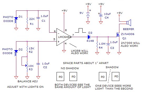
A much-better design is shown in the next circuit. It uses two photo-diodes
to compare the background light level and only register when there is a
difference. This allows the day to shine or the sky to overcast, without
affecting the alarm.
The circuit has been bread-boarded and put into a movie
HERE. (1Meg)
The improved circuit:
As I have said before. Ask yourself: Will the circuit work in all types of
different conditions and surroundings? What is the purpose of each component?
Is each component necessary? How much current does the circuit take in
quiescent ("idle") mode?
Are there better and cheaper ways to do the same thing?
That's why you need to study so many circuits, to get an idea of how to
design the cheapest and best arrangement.
You will learn more for other people's mistakes than any text book on
electronics.
Text books assume everything you construct will work.
After all, how many text books have a section "If it doesn't work?"
It's only when a project fails to work, that you will start to learn how the
circuit works.
That's why you can never get enough "mistakes" to investigate and
analyse.
Faulty Design
The next circuit is not a mistake but the author does not mention the output
does not rise above 1.2v for a 3v supply. This is only a 40% rise and will
not register as a HIGH, for many devices such as "gates" especially
those with a Schmitt trigger input. They need at
least 65% of rail voltage to detect a HIGH.
Secondly, the author has neglected to inform the output needs to be
connected to a very high impedance to allow the circuit to rise to its
maximum output.
The reason is the 4M7 in the circuit is the component that "pulls" the
output HIGH and if the output is connected to a circuit with an input of say
4M7, the output will rise to less than 1v.
There is no problem with the oscillator producing a LOW as the two
transistors are turned on by "regenerative action" and the output pulls LOW
with considerable "force" or "ability" or "current."
The circuit starts its cycle by charging the 4n7 via the 100M resistor. The
4M7 and 100M and 100M form a voltage divider that put a small voltage on the
base of the lower transistor.
The 4n7 charges and puts a voltage on the base of the upper transistor. The
emitter of the upper transistor sees a voltage that is about 0.6v lower than
the base and this voltage is placed on the emitter of the lower transistor.
When this emitter voltage is 0.6v higher than the base, the transistor turns
on and holds the emitter at its present potential. The transistor cannot
pull itself closer to the 0v line as this would remove some of the "turn-on"
voltage on the base.
However the lower transistor remains rigid and the top transistor turns on
more as the 4n7 charges.
The voltage on the collector of the top transistor reduces and this pulls
the top plate of the 0.1u capacitor towards the 0v rail. Since this action
is happening very fast, the capacitor does not have time to charge and the
bottom plate is also pulled towards the 0v rail
The bottom of the 0.1u is connected to the base of the lower transistor and
this is also taken lower.
This turns on the bottom transistor and the result is the top transistor is
turns on more. This is the regenerative action mentioned above and the two
transistors turns each other ON more and more until the they are both turned
on FULLY.
This whole action occurs without the need for the 4n7 to charge any further
and that's why the action is called regenerative.
We now have the situation where the two transistors are turned on and the
output is LOW. The very small voltage or "energy" stored in the 0.1u is now
passed into the base of the lower transistor to keep it in this "turned-on"
condition and this produces the 2mS LOW on the output waveform.
After 2mS, the lower transistor cannot be kept turned on and as soon as its
turns off slightly, the top transistor is turned off slightly as well and
the output rises. This happens very quickly and the top plate of the
capacitor rises and takes the lower plate with it. This turns off the lower
transistor and the two transistor are very quickly turned off fully.
As mentioned above, the output will not rise above 1.2v for a 3v supply and
this must be taken into account when connecting it to another stage.