|
|

PIC16F628 Data
(2.6MB .pdf)
Instruction Set for PIC16F628
PIC16F628A.INC
Library of Routines
A-E
E-P
P-Z
Blank_F628.asm
or Blank_F628.txt
Notepad.exe or Unzip
Notepad.zip.
START HERE
Updated 5/2/2009
![]()
The PIC16F628 is the starting point for PIC projects that require 6
to 15 "drive-lines."
(For 1 to 5 "drive-lines" use PIC12F629.)
Obviously you shouldn't
have a soldering
iron so hot that it fumes the solder.
The PIC16F628 has 2k of program space for your program (2048 lines
of code), operates at 4MHz and is cheaper than the PIC16F84A. The
4MHz oscillator is divided by 4 to get 1uS for each instruction.
We use the type number: PIC16F628 to describe this
microcontroller, but there are a number of part-numbers:
PIC16F628 - Internal 4MHz or 37kHz operation, 18pin
PDIP package (see photo below).
PIC16F628A Internal 4MHz or 48kHz operation, plus low
voltage programming, low speed clock mode, programmable BOR, on-chip
voltage reference.
-I/P I indicates temperature range: I = -40°C
to 85°C
(normally 0°C
to 70°C)
P = PDIP package (see photo below).>
E = -40°C
to 125°C
F = standard VDD
range 3v to 5.5v
LF = 2v to 5.5v
SO is surface mount
SS is surface mount
-04 = 4MHz
-20 = 20MHz
A chip with -20 means the chip is
capable of operating
at 20MHz via an external crystal and will execute 5 instructions per
second when the crystal is 20MHz. The chip has 4MHz and 37kHz
internal oscillators. The chip advertised by R S Components
(
www.rsaustralia.com) is
PIC16F628-20/P.
The PIC16F628A-20 I/P has 4MHz and 48kHz internal oscillators.
A "drive-line" is an input/output line capable of driving up to 25mA.
But this chip has one line that is input-only
and this must
be taken into account when designing a circuit. The input-only line
for PIC16F628 is RA5 - pin 4 and one line that is "input
and half-output" (RA4 - pin
3). (Other chips in the PIC range
also have one line that is either input-only or can only produce a
low-output - this applies to the PIC16F84. RA4 (pin 3) is an input
pin but when used as an output, it will only sink 25mA. It will not
source any current. And the PIC12F629 has GP3 (pin 4) as input
only.
Here is the pinout for the PIC16F628:
For a full explanation of each pin, refer
to PIC16F628 Data
(2.6MB .pdf).
Using a PIC in a circuit is very simple.
Here is a circuit to drive a LED. All you have to do is create about
30 lines of code and the LED can be made to flash.
UPGRADING FROM PIC16F84 TO
PIC16F628
MAKING RA4 SOURCE A CURRENT
If you want to sink
and source from RA4 for 'F84 or 'F628, one of the following circuits can be
used:
Circuit A has a HIGH of 4v and a LOW
of about 1v and an output of about 100mA. Circuit B has a HIGH of about 5.4v and
a LOW of about 0.6v and an output of about 250mA. Note: circuit B inverts the
output pin of the chip. There is a point when circuit B actually creates a short
across the power rail, when the output of the chip is changing from low-to-high
or high-to-low, but this interval is so brief that the transistors and power
rail will not be adversely affected.
TWO
"IN-CIRCUIT PROGRAMMING" MODES
The programming socket on your project can be can be 5 pins
as shown in the photo below and identified as Clock, Data, 0v,
5v and Vpp. The pins match the extension socket shown in the
picture. The extension "lead" consisting of a plug and socket fits into the 6 pins of the
Microchip programmer PICkit-2 and brings out the 5 lines we need for
In-Circuit Programming. (we do not use the first
line)
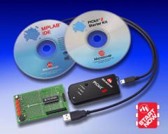
The PICkit 2 Starter Kit contains
a PICkit 2 Microcontroller Programmer and a
PICkit 2 Low Pin Count Demo Board containing a
PIC16F690 PDIP for getting started with
programming baseline and midrange flash
microcontrollers. PICkit 2 takes advantage of
Microchips Full-Speed USB device, thereby
significantly speeding up development
programming. The PICkit 2 Low Pin Count Demo
Board supports 8-, 14-, and 20-pin PICmicros. In
addition to the PIC16F690, the board comes with
4 LEDs, a pushbutton, and a pot. Also included
are 12 lessons to help get developers up to
speed quickly on programming PICmicro MCUs.
Features of PICkit 2 Starter Kit Low pin count demo board supporting
8/14/20-pin mid range PIC microcontrollers 20-pin PIC16F690 Midrange
microcontroller A series of 12
Lessons on
assembly programming that cover I/O, A/D converters,
timers, interrupts, and data tables (All source code
files are provided) Getting Started in PICBASIC PRO tutorial
on developing and debugging in BASIC with a FREE microEngineering
Labs PICBASIC PRO™ Demo Compiler (contained
on the PICkit-2 CD) HI-TECH PICC™ LITE C Compiler on
PICkit-2 CD. FREE! Microchip’s MPLAB
IDE software
for a complete code development environment
http://www.microchipdirect.com/productsearch.aspx?Keywords=DV164120
WHERE TO START:
The Comparison Chart will help you see
where the ports are located and the size of memory for your program.
PROGRAMMING THE PIC16F628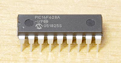
A PIC16F628A microcontroller - 4MHz
We found RA4 of a PIC16F84 is a sinking-line only and this is not covered anywhere
in any data sheet. To overcome this you need to add an
emitter-follower transistor with a 2k2 to the positive and the line
from the chip
connected to the base. See the circuit below.
Port B is a "full port" with 8 in-out lines but RB6 and RB7 are used
for "In-Circuit Programming" and these lines must be able to rise
HIGH when the chip is programmed "In-Circuit."
The PICkit-2 programmer does not
have the full 25mA "drive-capability" and thus the lines must be lightly
loaded.
If it is programmed "out of circuit," RB6 and RB7 can be used to
sink and source 25mA as per any of the other lines.
Port A has 6 in-out lines plus one input only line (RA5 - pin
4) and one "input
and half-output" (RA4 - pin
3). Thus the total is 14 plus one input
and "half-output"
and one input-only. The other two pins on
the chip are for power (5v) and connection to 0v.
The first thing to do is fit the microcontroller to an 18 pin socket
so it can be easily taken in out of a project. Wipe the pins of the
socket with hair-grease so it is easy to remove. Move the chip from
one place to another with the socket attached. This makes it much
easier to remove from the project and the programmer and prevents
your fingers getting spiked. Make sure pin
1 on the chip aligns with the notch at the end of the socket. You
can also put a white dot over pin1 to to make identification easy. 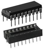
Fit the chip to a socket for
easy handling
The function of each pin
Port A (RA) and Port B (RB)
pins
clearly identified
Pre-written code
is available HERE as a .asm
or HERE as a .txt file
Helpful information on how to write a program
is available
A-E
E-P
P-Z
Simplest PIC16F628 circuit -
the
chip is sourcing
If you are upgrading from a PIC16F (or C)
84 (A), the pinout is below. Note all the port pins are in the same
positions on both chips. Port B is identical. Port A on the
PIC16F84 has 4
in/out and 1 "input and "half-output". The PIC16F628 has 6 in/out,
one "input and half-output" (RA4) and 1 input only (RA5).
The thing you have to remember is:
On both the PIC16F84 and PIC16F628, RA4 is an
"input and half-output". When used as an output, these
pins will only sink 25mA and source 0mA. To make the pin source,
connect the base of a transistor to the pin and put the transistor
in emitter-follower mode by connecting the collector to the positive
rail as in the diagram below.
RA5 on a PIC16F628 is input only.
RA4 will not deliver a
current to a load. To make it deliver a current, the following
circuit can be used.
Place a 2k2 on the base, to positive. When the pin is HIGH (or as an
input) the emitter will source (deliver) 25mA (or more) as the base is being
pulled HIGH by the 2k2. The current via the emitter is equal to the
base current multiplied by the gain of the transistor. When the output of the
micro is LOW, the base will be pulled low by the pin and the emitter
will be low. The circuit below will not allow for sinking a current. But
it makes
the pin source just like the other outputs. Don't forget, the
maximum current for the chip, via all the pins is less than 250mA,
to prevent overheating, so if you want to deliver a higher current,
this type of buffer circuit can be used. 
Making RA4 for 'F84 or 'F628 an output
Making RA4 for 'F84 or 'F628 a HIGH/LOW output
PIC16F84 Pinouts
The PIC16F628 chip can be programmed "in-circuit" providing the
programming pins are not used as output pins. If they are used as
output pins, the programmer will not have enough current to pull the
pin high to produce a guaranteed clock or data pulse. However the
pins can be lightly-loaded and the programmer will work.
The PIC16F628 chip has 2 ways it can be programmed. It has
Low-Voltage Programming and High-Voltage Programming.
Both ways can be done "In-Circuit." The method we are using is
called High-Voltage Programming as pin 4 receives a voltage slightly
higher than 13.5v to activate the chip into programming mode.
To activate the Low-Voltage Programming method, the chip must be
initially programmed via High-Voltage and the LVP bit set to "1" so
that either Low-Voltage or High- Voltage Programming can be done
"in-Circuit." In this state, Pin 10, RB5 cannot be used as
in-out as it must receive a HIGH so the chip goes into LVP mode.
In this case you lose an in-out pin and that's why we have not
chosen this mode.
We have chosen High-Voltage In-Circuit Programming mode.
Here are the programming connections. A separate programming board
can be made to connect to the PICkit-2. We can call this board a
PROGRAMMING BOARD as its only function is to program the chip. The
board will look just like the circuit below. The chip is then
removed and fitted to the project you are working on. Alternatively
the chip can be
programmed while in the project you are currently designing if you
include this socket and wiring.
In-circuit Programming
connections
The third photo/diagram below shows the Programming Socket on the circuit diagram above. You
can see how the PICkit-2 programmer sits at the back of your
project and the extension board fits over the 5 pins.
If your project operates on 4.5v, turn the power OFF as this low
voltage will upset the programmer.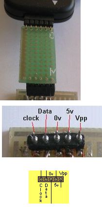
PICkit-2
Starter Kit
(from Microchip)
Here are the details of the
PICkit-2 programmer:
This programmer is the cheapest and best
for programming PIC chips and is available directly from
Microchip for $50.00 plus postage. It comes with CD's and an
extra PC board containing a PIC16F690 and components such as LEDs,
a push button
and a pot to get you started in programming. The
programmer detects the type of chip being programmed and
has features that help you to program the chip and
avoid mistakes and faults. It's a beautiful piece of
equipment. It connects to the USB port on
a lap-top. If you do not have access to a USB port, use the
Multi Chip Programmer
from Talking Electronics. Here is another
Programmer Cct.
Price:
USD$50.00
plus postage
DV164120 (purchase
via Microchip Direct)
Note: Requires the AC162061 ICD Header and AC164110
adapter to debug.
The PICkit-2 comes with a lead to connect
between the PICkit-2 and the USB port of your
laptop but you will still need to build the
extension plug-and-socket described above to fit between the PICkit-2
programmer and your project, so the PIC16F628 can be programmed.
You will be able to program "in circuit" if you put 5
pins on the project you are designing and connect
to the programming socket on the PICkit-2
programmer. Or you can build a separate
board called a PROGRAMMING BOARD and use the
extension plug-and-socket.
The 16F690 in the demo board is a complex chip and way-beyond
the needs of a beginner.
You still need to follow our instructions and build some of our
simple projects if you want to start at the beginning of
programming.
If you think you can come in on the "third rung of the ladder"
you are fooling yourself. You must do everything slowly and
methodically if you don't want to get frustrated. You must start
at the beginning.
If you are converting a program from one
micro to another (in the PIC family), here is a
comparison chart. It shows the locations of the Special File
Registers (from 000 to 06 or 1F). These include registers such as
OPTION, TIMER, STATUS etc and the input/output port(s) 05 (RA) and 06
(RB). The 25
files in PIC12C508A (36 files for PIC16C84, 68 files for PIC16F84
and 224 files for PIC16F628) are for temporary storage during the
running of a program and are accessed by this type of instruction:
movlw 0ffh
movwf
27h (this puts 1111 1111 into file 27h)
or movlw 080h
movwf 20h
(this puts the hex value 80 into file 20h)
bsf 22h,3
(sets bit 3 in file 22hex)
If you access file 05 by loading it with a value such as 03, (and
the file has been set as an output via the TRIS register, the
following two instructions will output a HIGH on the two lowest
output lines RA0 and RA1:
movlw 03h
movwf
05h
Note: the first temporary storage file for PIC16F628 is 20h.
The first thing you will want to do is program the PIC16F628. Don't
start with a complex project like "Simon." Start with a simple
project to turn a LED "on and off." To do this we have chosen the
Simon PC board for a set of 10 experiments to start you in
the world of programming. We will use the PC board to carry out the experiments.
PIC16F628 circuit
for experiments
CONSTRUCTION
Construction and testing of the PC board for this project is covered in the
SIMON project.
START HERE:
This project gets you started with the PIC16F628 microcontroller with 10
experiments.
It's the starting-point to learn about the wonderful word of "computer
projects."
You will be encouraged to add your own lines of code and experiment with
modifications to each experiment.
Remember to old saying: I see, I do, I learn.
EVERYTHING IS BASED AROUND A "COMPUTER"
Most new products are designed around a "computer"
Devices such as talking key-chains, whistle detectors to locate your keys,
remote controls for garage doors or cars, remote controls for TV, DVD, cable TV etc -
house alarms and toys are all designed around a single "computer" chip.
The reason is simple. It's economics.
A "computer" chip is one that has many functions, can
"remember" codes and inputs from the user.
Rather than design a circuit using lots of transistors, chips and components, it
is much cheaper to use a single chip. It takes less board-space, costs less to
produce and creates a smaller product.
All new designs are going for compactness and the latest trend is to produce something
smaller than the previous model.
And it all revolves around the heart of the product - a chip.
There are two choices. The chip can be a custom-design or "off the shelf."
Designing a chip will cost thousands of dollars. But in most cases you can buy one
that will perform the task for you, for only a few dollars.
Which would you choose?
Obviously a readily-available chip.
These "universal" chips are called microcontrollers and are equivalent to buying
a blank book such as an exercise book and writing your own story.
One of the smallest and cheapest microcontrollers on the market is the
PIC16F628. It has taken over from the
PIC16F84A and is now the cheapest and best way to start in
microcontroller-design.
(The PIC12F629 is about
half the size and will be covered in another article
- it has taken over from the PIC12C508A).
The PIC16F628 is an 18 pin chip with 15 pins that can be
connected to external devices such as globes, switches, relays, microphones,
photo devices, motors, etc.
Sometimes you will need a transistor or other components between the chip and the
device to get the external item to "talk" to the chip. This
is called INTERFACING and will be covered in our discussion.
Even though the PIC16F628 is very small as far a microcontrollers are
concerned, it can take the place of 10 or more individual chips.
Projects, such as a house
alarm, can be designed around the chip or you can get it to perform
"intelligent" commands such as playing a game of
Tic Tac Toe or remember a sequence
of events such as in the project:
Simon.
It has also been used in an automatic dialer project, taking the place of 17 chips.
The new design has 100-number capability. The old design could only dial 10 numbers!
This is where electronics is heading.
Every year, electronics is reducing is size, increasing in performance and
halving in cost.
New products are being released all the time using microcontrollers.
Devices such as auto-dialers for monitoring heart patients or diabetes suffers,
automatically dial a central station and download data to monitor the patient.
The computer decides if an alarm is to be raised.
The world is crying-out for devices to assist those unable to perform
important tasks.
But to be able to turn an idea into reality, you have to know the capability
of electronics and be able to carry out the design-work. You will lose-out
heavily if you pass your idea to another authority.
This is what this article is all about.
It shows some of the capabilities of a microcontroller and how to
get from the concept-stage to the finished product.
It's all a matter of doing things in small steps and
when these are combined together, you have something that will perform a task.
When it comes to programming, these small steps are called sub-routines and they
carry out a simple operation such as recognizing the push of a button, turning on a LED
or creating a tone
from a "speaker."
BLINK A LED
Here is a simple program that blinks (flashes) a LED on pin 6 (RB0) of a
PIC16F628.
;**************************************************************** ;* Name of Project: Flash A LED on RB0 *; ;**************************************************************** list P = 16F628 ;microcontroller identity ; e.g: 0x033 = hex value __Config 0x3FF5 ;**************************************************************** ;Program ;**************************************************************** org 0x00 ;start of program bsf status,rp0 ; select bank 1 movlw b'00001110' ; movwf option_reg bcf trisB,0 ; make bit,0 of Port B output bcf status,rp0 ;select programming area - bank0 movlw b'00000001' ; xorwf portB,f ; sleep end |
The program above is very simple, but how does it work?
There are a lot of hidden answers in the program.
Let's go through the instructions, one at a time.
The first instruction tells the assembler to put the next instruction at
location 000 in the "program space" in the microcontroller. There are 2048
locations in a PIC16F628 for your program.
The second instruction tells the micro to go to a location in the micro where
special purpose files are located.
The third instruction makes bits 1, 2 and 3 = "1" (the first bit is
bit,0).
These bits are placed in the Option Register and bit 1 and 2 increase the timing
of the Watch Dog Timer by 64 times by adding a prescaler. The normal timing of
the WDT is 18mS. It is now 1.15seconds.
The next instruction clears bit 0 of the register that makes each line of port B
either an input or an output. When a bit is "0" the corresponding line is and
output.
The next instruction bring the micro back to the programming area.
The next instruction put "1" into the working register.
XORWF has the effect of changing bits in a register to the opposite value,
when the bit in the working register is "1". In our case the lowest bit will
change from its unknown starting value to the opposite value.
The sleep instruction puts the micro to rest with any output pins remaining
HIGH.
"end" signifies the end of the program to the compiler.
HOW THE LED BLINKS
The micro executes each instruction in 1 microsecond and there are 7
instructions. It then comes to the sleep instruction.
The micro goes to sleep and the Watch Dog Timer executes 64 lots of 18mS and
wakes up the chip. The micro then goes to location 000 and executes the 7
instructions again.
The instruction XORWF changes the lowest bit in Port B to the opposite value and
goes to sleep again. This is how the LED is turned on and off.
This is not the normal way to produce a delay, but it shows how the sleep
instruction works and how the WDT operates.
The place to start writing a program is on a page already laid-out with preliminary details. It is a .asm page and is called "Blank_F628.asm" Save it as: Blank_F628.asm or view it as: Blank_F628.txt
Here is Blank_F628.asm:
;**************************************************************** ;* Name of Project: * ;* * ;**************************************************************** list P = 16F628 ;microcontroller list P = PIC16F628 include
|
To work on Blank_F628.asm, click on Notepad in our Programming
folder on the left-side of the screen and load it with the Blank_F628.asm file by
sliding it into Notepad. Rename the file immediately and work
on the renamed file.
Open
Notepad.exe or Unzip
Notepad.zip.
Click on "Blank_F628.asm" file and slide it onto the open Notepad. It will then
show in Notepad. Rename the file and save it. Work on the NEW file.
The "Blank_F628.asm" file may appear to be complex, so we have produced a simple
version with only the essential details. This is shown in Experiment 1.
Click on
experiment 1, click on Notepad.exe in the window, slide
Expt-1.asm into Notepad.
You can now work on Expt-1.asm
If you want to burn the first experiment into a PIC16F628, you can assemble the .asm
file in
MPASM to create a .hex file. To do this, place MPASM in a folder such as
desktop. Create a short-cut for MPASM.exe and place it on your desktop (or
unzip MPASM.zip).
Click on MPASM and it will open.
Place all the .asm and .hex into a folder and call it Experiments.
Locate Expt-1.asm in the folder and load it into MPASM.
Use:
Radix: Default, Warning Level: Default, Hex Output: Default,
Generated Files: Error File and List file, Do not tick: Case Sensitive,
Macro Expansion: Default, Processor PIC16F628, Tab Size: 8, Tick: Save
settings on exit.
Click: Assemble.
Your
Expt-1.hex file will be put into the same folder as our Expt-1.hex file, so give
your program another name so it does not overwrite the original file.
To burn a PIC16F628, you will need the
Multi Chip Programmer.
Make sure the programmer is the latest version with 628 on the underside of the
PCB.
Connect it to your computer via the serial cable supplied in the kit and the
green LED will illuminate.
If you have a laptop, you will have to use MicroChip programmer PICkit-2.
This programmer connects to your USB port.
Install IC Prog on
your desktop or unzip
IC Prog.zip
Click on the folder on the top left-hand side and locate Expt-1.hex
Make sure you have selected PIC16F628 before loading the .hex file.
The configuration settings will be automatically set according to the
configuration value supplied in the program - or you can change anything before
burning the new program.
Fit a chip into the programmer board (If you use PICkit-2, see above for
the layout of the programming board and the plug-and-socket to connect the board
to PICkit-2 and use the programming software that comes on a CD with the kit) and click on the "lightning" icon for
IC Prog.
The programmer will now burn the program into the chip. The LEDs on the
Multi-Chip Programmer will show the action taking place.
When the chip is "burnt," place it in the socket on the project and push the red
button. The red LED will illuminate.
This might seem a lot of work to create a simple effect, but the same amount of
work will produce a compete project, such as a simple video game or health
monitor - it's just the size of the program will be
different.
Now we will start on a few Experiments:
EXPERIMENT 1
In SetUp, the instructions: movlw 0x07 movwf cmcon
turn comparators off and enable all pins for I/O functions - especially RB4 (pin
10), as it is the Low Voltage Programming pin and when it is enabled for
low-voltage in-circuit programming, this pin will not operate as an in-out pin.
When the red push-button is pressed, the red LED illuminates. When the
button is released, the LED extinguishes.
Experiment 1 consists of 6 lines of code in a sub-routine called Main.
All the other instructions set-up the micro so the ports are
ready to "talk" to the outside devices.
The first thing to remember is
the micro NEVER stops. It keeps executing instructions at 1,000,000 per
second.
This means the main sub-routine must be a loop. This is what we have
done.
The first instruction in Main: btfss 06,0 is called a "bit
testing instruction." It tests bit zero of Port B to see if the
push-button has put a HIGH or LOW on the input. The micro "reads" the
value on the line and if it is above about 4v, it is interpreted as a HIGH. If
it is below about 2v, it is a LOW.
If it is HIGH, the micro jumps to the third instruction and sets bit 4 of
Port B and this turns ON the LED. The micro then goes to Main and
executes btfss 06,0 again and the remaining instructions. The micro keeps
looping these instructions while the push-button is pressed.
When the button is released, the first instruction finds the input is not
set (not HIGH) and goes to the second instruction where it is told to go
to Main1. At Main 1 the micro clears bit 4 of
Port B and this turns OFF
the LED. The micro then goes to the next instruction where it is told to
go to Main. This creates another loop that keeps the LED off. There are
two slightly different loops and the micro is constantly looping one of them.
;**************************************************************** ;* Name of Project: Experiment 1 * ;* Push red button RB0 to turn on red LED RB4 * ;**************************************************************** list P = 16F628 ;microcontroller identity ; e.g: 0x033 = hex value __Config 3F18h ;**************************************************************** ;Equates ;**************************************************************** status equ 0x03 cmcon equ 0x1F rp1 equ 0x06 ;this is bit 6 in file 03 rp0 equ 0x05 ;this is bit 5 in file 03 ;**************************************************************** ;Beginning of program ;**************************************************************** reset: org 0x00 ;reset vector address goto SetUp ;goto set-up nop nop nop org 4 ;interrupts go to this location goto isr1 ;goto to Interrupt Routine - not used ; in these experiments. ;isr1 must be written at address 004 ; otherwise bcf status,rp1 will be ; placed at address 01 by assembler! ;**************************************************************** ;* Port A and B initialisation * ;**************************************************************** SetUp bcf status,rp1 ;select bank 1 (must be = 0) bsf status,rp0 ; also to select bank 1 movlw 0xFF ;make all Port A inputs movwf 0x05 movlw 0x0F ; out out out out in in in in movwf 0x06 ; bcf status,rp0 ;select programming area - bank0 movlw 0x07 ;turn comparators off and enable movwf cmcon ; pins for I/O functions goto Main ;**************************************************************** ;* Interrupt Service Routine will go here (not used) * ;**************************************************************** isr1 ;**************************************************************** ;* Main * ;**************************************************************** Main btfss 0x06,0 ;Port B, input bit 0 = red button pushed? goto Main1 bsf 0x06,4 ;Port B, output bit 4 = turn on red LED goto Main Main1 bcf 0x06,4 ;Port B, output bit 4 = turn off red LED goto Main END |
EXPERIMENT 2
Experiment 2 adds the orange button and
orange LED.
The program will recognise only one
button at a time.
;**************************************************************** ;* Name of Project: Experiment 2 * ;* Push red button to turn on red LED * ;* and orange button to turn on orange LED * ;**************************************************************** list P = 16F628 ;microcontroller identity ; e.g: 0x033 = hex value __Config 3F18h ;**************************************************************** ;Equates ;**************************************************************** status equ 0x03 cmcon equ 0x1F rp1 equ 0x06 rp0 equ 0x05 ;**************************************************************** ;Beginning of program ;**************************************************************** reset: org 0x00 ;reset vector address goto SetUp ;goto set-up nop nop nop org 4 ;interrupts go to this location goto isr1 ;goto to Interrupt Routine - not used ;isr1 must be written at address 004 ; otherwise bcf status,rp1 will be ; placed at address 01 by assembler! ;**************************************************************** ;* Port A and B initialisation * ;**************************************************************** SetUp bcf status,rp1 ;select bank 1 (must be = 0) bsf status,rp0 ; also to select bank 1 movlw 0xFF ;make all Port A inputs movwf 0x05 movlw 0x0F ;out out out out in in in in movwf 0x06 ; bcf status,rp0 ;select programming area - bank0 movlw 0x07 ;turn comparators off and enable movwf cmcon ; pins for I/O functions goto Main ;**************************************************************** ;* Interrupt Service Routine will go here (not used) * ;**************************************************************** isr1 ;**************************************************************** ;* Main * ;**************************************************************** Main btfsc 0x06,0 ;Port B, input bit 0 = red button pushed? goto Main1 ;Yes btfsc 0x06,3 ;Port B, input bit 3 = orange button pushed? goto Main2 ;Yes clrf 0x06 ;turn off all LEDs goto Main Main1 bsf 0x06,4 ;Port B, output bit 4 = turn on red LED goto Main Main2 bsf 0x06,7 ;Port B, output bit 7 = turn on orange LED goto Main END |
EXPERIMENT 3
4 push-buttons display 4 LEDs.
This is an extension of experiment 2. It is your job to copy and paste Main into a .asm file,
add the set-up instructions and create a .hex
file via MPASM:
;****************************************************************
;* Name of Project:	Experiment 3		*
;* 4 push-buttons and 4 LEDs			*
;****************************************************************
See above for set-up instructions

;****************************************************************
;* Main 					*
;****************************************************************

Main	btfsc	0x06,0	;Port B, input bit 0 = red button pushed?
	goto	Main1	;Yes
	btfsc	0x06,1	;Port B, input bit 1 = green button pushed?
	goto	Main2	;Yes
	btfsc	0x06,2	;Port B, input bit 2 = yellow button pushed?
	goto	Main3	;Yes
    	btfsc	0x06,3	;Port B, input bit 3 = orange button pushed?
	goto	Main4	;Yes
	clrf	0x06	;turn off all LEDs
	goto	Main
Main1	bsf	0x06,4	;Port B, output bit 4 = turn on red LED
	goto	Main
Main2	bsf	0x06,5	;Port B, output bit 5 = turn on green LED
	goto	Main
Main3	bsf	0x06,6	;Port B, output bit 6 = turn on yellow LED
	goto	Main
Main4	bsf	0x06,7	;Port B, output bit 7 = turn on orange LED
	goto	Main
	END
|
EXPERIMENT 4
4 push-buttons in "toggle-mode." Push red button momentarily and it
turns on red LED. Push the button again and the LED turns off.
The program requires "switch-debounce" instructions.
All switches suffer from "bounce" this is the action of the two contacts
coming together and moving away very quickly, during the time when the
button is pressed or released.
You may think the contacts simply open and close, but they can make a
number of connections during the process of coming together or parting. This is due
to dirt on the contacts and the rough surface. The micro is executing the
program so quickly that it sees these bounces as "opening and closing"
and doesn't know if the LED should be ON or OFF.
To solve this problem we need to put a delay between button-presses of
approx 1/10th second (100,000 instructions!).
This means the program will only see the press of a button or the release
during each 1/10th second operation.
To change the state of a LED we use an instruction that toggles the corresponding bit on the
output port. The instruction is XORWF.
The working register (w) is loaded with the bit we want to toggle.
The output port is XOR'ed with w and the result is placed in file
06 (the output port).
You need to know how the XOR function works to understand how the
result is produced and this is covered in the
PIC Programming Course
- XOR.
We will use file 30h for the flag file and files 20h and 21h for the
delay sub-routine.
The delay provide "heavy debounce" for the keys and prevents fast-pushing
being detected.
The micro is looping the Main routine very quickly and it needs to know
when a button has been released so it can perform a toggle action when it
detects a button is pressed for the second time.
This information is kept in a "flags file" (file 30h) and the four lowest
bits 0, 1, 2, and 3 are used.
To prevent a key "repeating" the flag-bit must be set and
cleared. When a key is detected, the flag is tested to see if it is
clear. If so, the LED is toggled and the flag is set.
The micro will very quickly produce a second-pass where it detects the
key again. It will find the flag is set and no action is taken. When the
key is released, the flag bit is cleared.
;**************************************************************** ;* Name of Project: Experiment 4 * ;* 4 push-buttons and 4 LEDs * ;**************************************************************** list P = 16F628 ;microcontroller identity ; e.g: 0x033 = hex value __Config 3F18h **************************************************************** ;Equates ;**************************************************************** status equ 0x03 cmcon equ 0x1F rp1 equ 0x06 ;this is bit 6 in file 03 rp0 equ 0x05 ;this is bit 5 in file 03 portA equ 0x05 ;file 5 is Port A portB equ 0x06 ;file 6 is Port B flags equ 0x30 ;flag file decrA equ 0x20 ;file to decrement decrB equ 0x21 ;file to decrement **************************************************************** ;Beginning of program ;**************************************************************** reset: org 0x00 ;reset vector address goto SetUp ;goto set-up nop nop nop org 4 ;interrupts go to this location goto isr1 ;goto to Interrupt Routine - not used ;isr1 must be written at address 004 ; otherwise bcf status,rp1 will be ; placed at address 01 by assembler! ;**************************************************************** ;* Port A and B initialisation * ;**************************************************************** SetUp bcf status,rp1 ;select bank 1 (must be = 0) bsf status,rp0 ; also to select bank 1 movlw 0xFF ;make all Port A inputs movwf portA movlw 0x0F ; out out out out in in in in movwf portB ; bcf status,rp0 ;select programming area - bank0 movlw 0x07 ;turn comparators off and enable movwf cmcon ; pins for I/O functions goto Main ;**************************************************************** ;* Interrupt Service Routine will go here (not used) * ;**************************************************************** isr1 ;**************************************************************** ;Delay sub-routine - approx 130mS ;**************************************************************** delay movlw 0x80 ;load 80h into w movwf decrA ;shift 80h into the file for decrementing delx nop decfsz decrB,1 ;decrement the file goto delx decfsz decrA,1 ;decrement the file goto delx retlw 0x00 ;return ;**************************************************************** ;* Main * ;**************************************************************** Main clrf flags MainA call delay ;1/10 second delay btfsc portB,0 ;file06, input bit 0 = red button pushed? goto Main1 ;Yes btfsc portB,1 ;file06, input bit 1 = green button pushed? goto Main2 ;Yes btfsc portB,2 ;file06, input bit 2 = yellow button pushed? goto Main3 ;Yes btfsc portB,3 ;file06, input bit 3 = orange button pushed? goto Main4 ;Yes clrf flags ;clear flag file goto MainA ;No. Loop again Main1 btfsc flags,0 ;test red flag goto MainA ;return if flag is SET movlw 0x10 ;set the bit for the red LED xorwf portB,1 ;put answer into file 06 to toggle LED bsf flags,0 ;set the red flag goto MainA Main2 btfsc flags,1 ;test green flag goto MainA ;return if flag is SET movlw 0x20 ;set the bit for the green LED xorwf portB,1 ;put answer into file 06 to toggle LED bsf flags,1 ;set the green flag goto MainA Main3 btfsc flags,2 ;test yellow flag goto MainA ;return if flag is SET movlw 0x40 ;set the bit for the yellow LED xorwf portB,1 ;put answer into file 06 to toggle LED bsf flags,2 ;set the yellow flag goto MainA Main4 btfsc flags,3 ;test orange flag goto MainA ;return if flag is SET movlw 0x80 ;set the bit for the orange LED xorwf portB,1 ;put answer into file 06 to toggle LED bsf flags,3 ;set the orange flag goto MainA END |
EXPERIMENT 5
The buttons can be configured to almost anything. That's the advantage of using a programmable chip as the basis of the project. They can be configured to turn on any LED or two or three LEDs at the same time or a single button may need to be pressed a number of times to produce an effect.
This experiment is a puzzle. One of the buttons turns on a LED.
It must be pressed in a "time-sequence." Another button resets the sequence.
You are not told which button to press or the sequence. You have to find out yourself.
You will surprised at the difficulty.
This type of sequence can be used to activate an alarm or entry code to a house or room.
Added security can be provided by locking the system for 15 minutes if more than 10 pushes are detected.
Burn the program into the chip and try to work out the sequence.
;**************************************************************** ;* Name of Project: Experiment 5 * ;* Push-button puzzle. Push a button a number * ; of times to turn on a LED * ;**************************************************************** list P = 16F628 ;microcontroller identity ; e.g: 0x033 = hex value __Config 3F18h **************************************************************** ;Equates ;**************************************************************** status equ 0x03 cmcon equ 0x1F rp1 equ 0x06 ;this is bit 6 in file 03 rp0 equ 0x05 ;this is bit 5 in file 03 portA equ 0x05 ;file 5 is Port A portB equ 0x06 ;file 6 is Port B flags equ 0x30 ;flag file timerA equ 0x20 ;file to decrement timerB equ 0x21 ;file to decrement timerC equ 0x22 ;file to decrement counter equ 0x23 ;file to increment **************************************************************** ;Beginning of program ;**************************************************************** reset: org 0x00 ;reset vector address goto SetUp ;goto set-up nop nop nop org 4 ;interrupts go to this location goto isr1 ;goto to Interrupt Routine - not used ;isr1 must be written at address 004 ; otherwise bcf status,rp1 will be ; placed at address 01 by assembler! ;**************************************************************** ;* Port A and B initialisation * ;**************************************************************** SetUp bcf status,rp1 ;select bank 1 (must be = 0) bsf status,rp0 ; also to select bank 1 movlw 0xFF ;make all Port A inputs movwf portA movlw 0x0F ; out out out out in in in in movwf portB ; bcf status,rp0 ;select programming area - bank0 movlw 0x07 ;turn comparators off and enable movwf cmcon ; pins for I/O functions goto Main ;**************************************************************** ;* Interrupt Service Routine will go here (not used) * ;**************************************************************** isr1 ;**************************************************************** ;timer sub-routine - approx 130mS ;**************************************************************** Delay movlw 0x80 ;load 80h into w movwf timerA ;shift 80h into the file for decrementing Delay1 nop decfsz timerB,1 ;decrement the file goto Delay1 decfsz timerA,1 ;decrement the file goto Delay1 retlw 0x00 ;return ;**************************************************************** ;* Main * ;**************************************************************** Main clrf flags clrf counter MainA movlw 0x01 movwf decrC call delay ;250mS delay btfsc portB,1 ;file06, input bit 1 = green button pushed? goto Main2 ;Yes btfsc portB,2 ;file06, input bit 2 = yellow button pushed? goto Main3 ;Yes btfsc portB,3 ;file06, input bit 3 = orange button pushed? goto Main4 ;Yes clrf flags ;clear flag file goto MainA ;No. Loop again Main1 btfsc flags,0 ;test red flag goto MainA ;return if flag is SET movlw 0x10 ;set the bit for the red LED xorwf portB,1 ;put answer into file 06 to toggle LED bsf flags,0 ;set the red flag goto MainA Main2 btfsc flags,1 ;test green flag goto MainA ;return if flag is SET movlw 0x20 ;set the bit for the green LED xorwf portB,1 ;put answer into file 06 to toggle LED bsf flags,1 ;set the green flag goto MainA Main3 btfsc flags,2 ;test yellow flag goto MainA ;return if flag is SET movlw 0x40 ;set the bit for the yellow LED xorwf portB,1 ;put answer into file 06 to toggle LED bsf flags,2 ;set the yellow flag goto MainA Main4 btfsc flags,3 ;test orange flag goto MainA ;return if flag is SET movlw 0x80 ;set the bit for the orange LED xorwf portB,1 ;put answer into file 06 to toggle LED bsf flags,3 ;set the orange flag goto MainA END |
| |
|
4-6-2012