|
|
|
|

|
|

Index
12 FREE PIC Books Simply download the books via Rapidshare.
Lots of PIC micro information on
this website.
or here:
more downloads
START HERE
Chapter 1
Microchip claims to be the #1 in microcontrollers.
This is possibly true as they recently sold their billionth
chip to a Chinese manufacturer.
The reason I recommend microchip is simple:
The back-up is enormous.
A huge number of projects have already been designed
by hundreds of programmers.
A "PIC Web-ring"
on the internet will answer any questions.
The chips are "cheaper than ever."
And you can create a circuit in which the program is
safe from "prying eyes" via a security feature.
In fact, microcontrollers are the only way to go . . .
This is Chapter 1
It starts you at the beginning of making/creating/building a project using a microcontroller.
Electronics is enormous and the most interesting projects use a microcontroller.
In this chapter we start you with one of the simplest microcontrollers on the market and we show how to make really interesting projects.
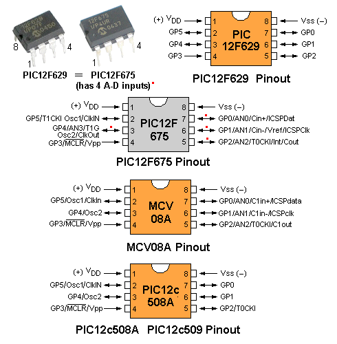
The chip is the PIC12F629. It has 8 pins, 5 output lines with 25mA drive-current each. These can be configured as input (that's why they are called input/output lines) and one other line is input-only. The chip has 1024 spaces for your program (i.e: 1024 lines of code or data), 128 bytes of EEPROM memory (data will be retained when the power is removed) and 4MHz internal oscillator.
Here are 2 circuits using the PIC12F629, (and see 6 more circuits HERE).
But first you must read all this chapter so you can see what we have
produced. Then you will be able to work out what project you want to
build and how you will program the chip.
All the projects are designed around the "simplest microcontroller on
the market." These will be appearing one or all of the three best
electronics magazines you will find in your newsagent:
Elektor,
EPE,
Silicon Chip, over
a number of issues but since the space in the magazine is limited to a few pages
per issue,
only the main parts will be described and the full article will be on the
web - right here!
The web is a "most amazing" place. It offers an "endless page"
with full-colour at no extra cost and since we have provided an enormous
amount of detail for each article, including links to other pages, we
will be using the resources of the web to the fullest.
You will find this series most fascinating as it introduces the
art of programming PIC microcontrollers when they are soldered to the
board.
We start at the beginning with one of the simplest PIC chip on the
market (PIC12F629) and show what can be done with 8 pins. There are
smaller 6 pin chips, and the one we suggest is:
PIC10F222. But the cost of this
smaller chip is the same as the PIC12F629, so why increase your
inventory and complicate things?
THE BIG QUESTION . . .
Why do we write so much in each article?
Because many projects in magazines are designed by brilliant electronics engineers
and they expect everyone who reads the article to understand how the
project works. But all readers are not brilliant on every topic and sometimes a small amount
of explanation will make a project more understandable.
Since we don't know which part of the article requires
additional comment, we cover it all.
In all our books and magazines we have never been charged
with writing too much.
On the contrary. Readers like the in-depth approach. It removes so much
frustration. It took me more than 3 days to work out how a brilliant
clocking cycle worked in a counter chip project, some 20 years ago and I
don't want this frustration to occur with any of my projects.
ASSEMBLY LANGUAGE
All the instructions for the projects are written in ASSEMBLY LANGUAGE.
Examples of
this are: decf (decrement the file "f") clrf (clear
"f") and an instruction such as "decrement file 2Ah (2A is
hexadecimal) and place the result in the file", is written as:
decf 2Ah,1
The ,1 indicates the result is placed in the named file and this is the
same as ,F or ,f If you write decf 2Ah,0
the result will be placed in "w" and the named file will not be altered!
These instructions are actually called mnemonics as they contains letters
or sounds similar to the wording of the instructions. This type of
programming is called "Low-Level" as it is very close to the
numbers ("0's" and "1's") that are understood by the microprocessor.
In other words there is a simple look-up table to
convert our instructions to "machine instructions" and this
conversion is done by a program called an assembler, when it changes the
assembly code (assembly language) we have written, into numbers (actually a string of "0's"
and "1's") that are understood by the microcontroller
(actually the microprocessor inside the chip). A
microcontroller is a chip containing a microprocessor and additional
items such as memory and drive-lines to allow the microprocessor to
connect to the outside world.
The 33-35 instructions we use to produce all our programs are very easy to remember. Every feature
(capability) of
the chip can be carried out with these instructions and you can compare
this to being given the 26 letters of the alphabet. All other languages are
called "High-Level" as they need an interpreter to convert the
instructions you produce
into instructions that can be understood by the micro. There is no problem with this but
you need to lean how to write High-Level programs.
By using the micro's 33 instructions you can start programming
immediately. We call our technique "Cut and Paste" where you move lines
of code into your program from sub-routines we have already produced.
WHAT CAN THE CHIP DO?
One of the first questions you will ask is: What can the chip do?
It's
best to look at the projects below to see this.
Don't forget, we are using one of the smallest chips on the market and we have
designed many projects, including a telephone dialer, Vox bug,
timer, Infinity Bug, heating controller and more, so its capability is
quite impressive. If you try and compare the chip with old-style
logic chips, such as NAND gates, OR-gates, inverters and comparators etc, it could easily
replace 20 or more chips and still produce a smarter design.
Here is a typical example. It is a Code Puzzle circuit using discrete
chips. Our project uses a single chip and produces a higher degree of
sophistication:
To see more ideas, look at the projects
below.
Everything is documented with step-by-step instructions and this is the
first time you will be guaranteed to get a project working. Everything
you need is included on this site and a
Library of
Instructions and
Routines has been included to help you with writing a program.
Our method is called "Cut and Paste."
A blank
template is available for the chip and by cutting and pasting
sub-routines from other projects, you can create your own program with
the least effort. You will also need the "include" file for the
programmer: p12F629.inc
The original application for the first PIC chip to be invented, was to interface a program to a computer to prevent pirate copying. It was fitted in a lead called a "dongle" and worked so fast and efficiently that is was used in other applications.
This brought a huge following on the internet and created considerable interest with "PIC discussion groups."
Clones appeared and one company designed an easy to program module around the chip using a higher-level language called BASIC.
Their BASIC program filled the chip and only allowed room for about 40 BASIC instructions in a section called EEPROM (memory that does not disappear when the power is removed).
A BASIC instruction will carry out a greater command than a single mnemonic instruction but overall the concept reduced the capability of the chip considerably.
This did not pose a major problem as the chip has such a high capability that it is rarely completely used.
So, if you are worrying about running out of program space or the chip is too small or too simple for a project, just look at what we have done and see what type of projects are suitable for this 8-pin device.
Before finishing, there is one important reason why we chose the lowest level language for programming.
If a sub-routine has a fault and doesn't work, you will be able to see the instructions and work out what is going wrong.
But most-important, by using our programming method, the program will be the shortest and you can code-protect the chip to prevent it being copied.
This is essential if you are on the path to designing a product that needs protection.
There are thousands of products being invented each year requiring a simple processor such as the one we are promoting. Look at the toy area, medical aids or the "touch and go" swipe card. These types of things will create sales in the millions and obviously the program will be contained in a COB (Chip On Board) in the final design, but the initial stage will involve discrete components.
IN-CIRCUIT PROGRAMMING
All the projects in this series involve surface-mount componentry and IN-CIRCUIT PROGRAMMING. (You can use though-hole components and you can use normal programming).
The three areas we cover are:
1. Building a surface-mount project.
2. Writing a program for a PIC chip.
3. Programming a PIC chip via In-Circuit Programming.
PIC chip are available as through-hole devices or surface mount. When selecting the surface-
mount version, the project will need to have a programming socket and wring to the chip so the chip can be programmed and re-programmed as you develop and modify the program during development.
When selecting the through-hole device, you can program the chip via a parallel programmer, using our Multi-Chip Programmer, or serially, via the USB port, using the PICkit-2. The Multi Chip Programmer has an interface cable for In-Circuit Programming but the programmer does not have any "driving" capability to program a chip when items are connected to the output lines.
PICkit-2 is more expensive but has some "driving" capability.
You need to read all the articles before deciding which programmer you will use.
Basically the decision is simple: If you have a "tower" computer with a serial port, the Multi Chip Programmer uses the serial port and voltages of the RS-232 to program the chip.
If you have a lap-top computer with USB, you will need to buy the PICkit-2.
If you buy the Multi Chip Programmer, you will need a cable to connect the programmer to the computer. This cable is called: SERIAL CABLE.
If you buy the PICkit-2, it comes with a connecting cable.
BEFORE YOU START
Before you start building anything, you need to read the following articles to learn about the PIC chip, surface-mount technology, programming skills and how to get a project "off the ground."
Start by reading about the PIC12F629 microcontroller Page 1.
Read the article on PROTOTYPING.
Read the article on: Programming Board for Surface Mount PIC and through-hole micro. (includes Connector Boards for both types of chips).
Read the article on PROGRAMMING.
You will now have an idea of some of the steps involved in getting an idea "off the ground."
The next thing to do is construct a programming board and "burn" some of the experiments into the micro and see the results.
To do this you will need to buy the PICkit2 programmer, the programming board (for the surface-mount chip) and the connector. If you want to program only the through-hole chip, you can buy the programming board and connector for the through-hole chip.
THINGS YOU WILL NEED
Before you get to any of the projects, you will need to construct the programming board (called SM-8 board) for a surface mount chip (and components) to test your IN-CIRCUIT PROGRAMMING skills. You will need an IN-CIRCUIT PROGRAMMER called PICkit2 and CD's that come with the programmer.
You will also need to build a connector (called SM connector-1) to go between the programmer and the PC board.
We also have a board for a through-hole 8-pin chip (called Dev-8 board) so you can program a microcontroller for other projects. We also have a connector to go between the programmer and the development PC board (called Dev-8 connector-1).
All the projects in the series come with a pre-programmed PIC chip and a programming socket so the chip can be modified while it is soldered to the board. The projects also have lands for the surface-mount version of the chip as well as the through-hole version. The 8-pin socket for the through-hole version is soldered to the lands around the edges of the surface-mount lands so the socket sits above the positions where the surface mount chip is designed to be placed. This gives you the opportunity to use either a surface-mount or standard chip.
THIS IS WHERE YOU START
1. Create a folder called PICkit-2 Files.
On your desktop, create a new folder with the wording PICkit-2 files. It will look like the following:

Create a link from this icon so that when you click on the icon, all the files in the folder will appear on the screen.
This folder will also have (eventually) lots of folders and each folder will have the files associated with each project that you will be developing.
Each time you start a new project, you will add another folder to the folder containing all your work.
You will start a new project by copying one of the project we have produced and then you will change some of the instructions and work from there. If you want to start from scratch, you can use blank template. This program will be written on NotePad2 and saved as xxxxxxxx.asm You can have only 8 characters in the name.
blank template
NotePad2.exe
.inc files
In each project-folder you must put the .inc file corresponding to PIC12F629.
From the .inc files, just choose P12F629.inc
2. On your desktop, place an icon like the following:

Create a link so that when you click on the icon, you will get MPASM appearing on the screen with the following image:
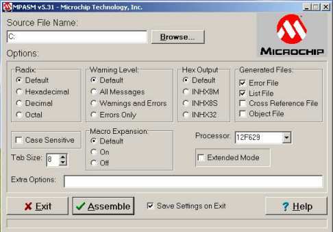
MPASM can be in the PICkit-2 Files folder.
You must set up the screen so that it shows the same outputs etc as in the image above.
3. On your desktop, place an icon like the following:

In the PICkit-2 Files folder, place the following program: PICkit2V2.exe
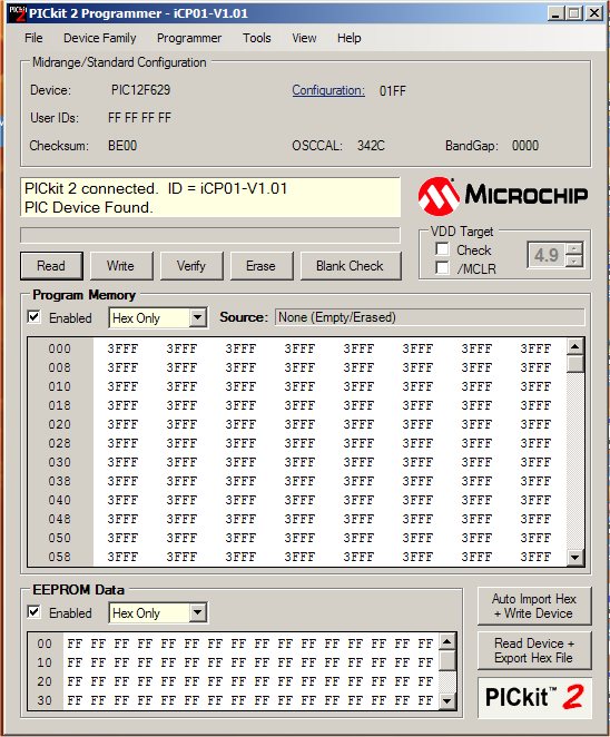
Create a link so that when you click on the icon, you will get PICkit-2 appearing on the screen with the following image:
You will now have 3 icons on your desktop like this:
1. When you begin or change or modify or start a program, you will start by clicking on the first icon (above) and this will bring up all your folders containing all your PIC programs.
You will click on the appropriate folder and find the .asm file
You will work on the .asm file and save it. This is done in a program called: NotePad2
2.Then click on the MPASM icon (above) and this will display the program that will operate on the .asm file and assemble it to produce 4 more files: COD file .ERR file .HEX file .LST file and you will have 5 files.
If your program contains mistakes, only the .ERR file will appear and we will deal with that later.
Otherwise 5 files means the program has assembled correctly.
3.You are now ready to "burn" the program into the PIC chip.
This is done with a PICkit-2 programmer like this:
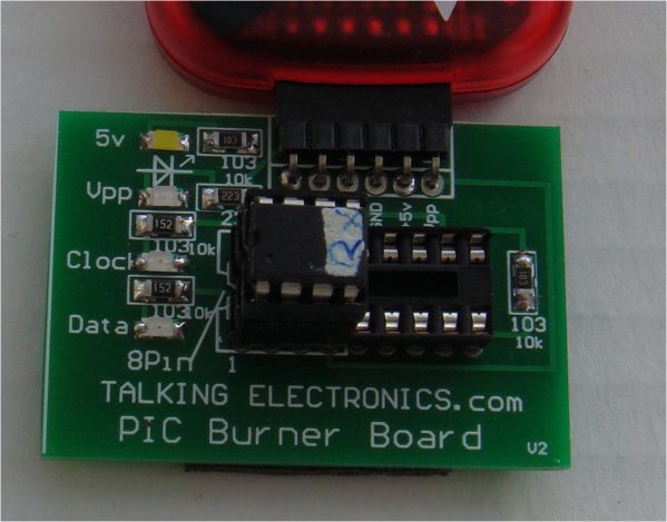
The PICkit-2 programmer needs to be connected to Talking Electronics PIC Burner Board to make burning easy:
Connect the PICkit-2 programmer to a USB socket (via the cable supplied) and click on the PICkit-2 icon and it will find the PICkit-2 programmer and display the following:
That's the end of setting-up. We will now go over the next set of things to do: (there may be some repeats)
SETTING UP PICkit2
Place the PICkit2 programmer near
your laptop.
Connect the interface cable between the USB port and the PICkit2
programmer
Fit the interface plug between PICkit2 and the programming board for
either a surface-mount PIC chip or through-hole chip.
Place the .asm file Blink.asm in a folder AT THE TOP OF YOUR
FOLDERS (MPASM does not like long extensions), such as "A -
PICkit2files"
Load MPLAB IDE CD and go to START on your computer and "right click" to
get "Explore."
Locate drive D: and install the files in a folder called: "A - MPLAB" Go
to MPASM Suite and locate MPASMWIN.exe and right click. A window will
open with "Send to" Send to desktop (create shortcut). Close
all windows and the shortcut will be on your desktop. Move it to a new
position on the desktop and right click on the icon. Remove all the
wording and leave MPASM below the icon on your desktop.
Insert the CD PICkit Starter kit CD.
Go to Start on your computer and right click to get "Explore."
Go to D: and click on the folder "Install."
Click on PICkit 2.
Click on "setup.exe"
It will create a file "Microchip" in your "Programs Files."
A folder PICkit 2 v2 will be created and in this folder will be:
PICkit2V2.exe and an icon on your desktop.
Alternatively, insert PICkit Starter kit CD and click "Installs" on the
front screen. This will bring up a box to automatically install "setup.exe"
Go to your desktop and put the PICkit icon next to MPASM and rename it
PICkit.
Place the folder containing your files on the desktop by going to
"Start" Right click to get "Explore" Right click on
your files folder and "send to Desktop (create shortcut). Place the icon
near MPASM and PICkit2.
Install NotePad2.exe in "Program Files" (Download
NotePad2.exe as NotePad2.zip) Unzip it and place it in
"Program Files."
Click on "PICkit2 files" icon on your desktop and select any .asm file.
Right Click and select "Properties" at the bottom. Find: "Open
with" and push the "change" button. Find NotePad2.exe in "Program Files"
and use this to open all your .asm files.
You are now set up.
You have now placed the files from the CD onto your computer, used the
PICkit2 serial programmer on your serial port, built the interface
connector to fit between the PICkit2 programmer and programming board,
built the Programming Board for either the surface-mount PIC12F629 or
through-hole version, (it also contains LEDs and components for the experiments).
You must prove the programmer is working by going through the
experiments to turn a LED on/off etc before starting any of the
projects.
You
can now construct one or more of the projects in this series:
PROJECT 1
SKY WRITER
This project uses a PIC12F629 and 6 LEDs to produce words "in space."
The project is waved through the air to produce words or any character
or symbol you program into memory.
PROJECT 2
FIND THE NORTH POLE
This project uses a PIC12F629, an inductor and an op-amp to detect the
magnetic field of the earth and identify the direction of the north
pole. A simple requirement, but an amazing thing to do with electronics.
PROJECT 2a
SPIN THE DICE
This project uses the FIND THE NORTH POLE board. It is mounted on a "top" and spun to produce the pips on a
dice. The earth's magnetic orientation is used to reference the start of
the display.
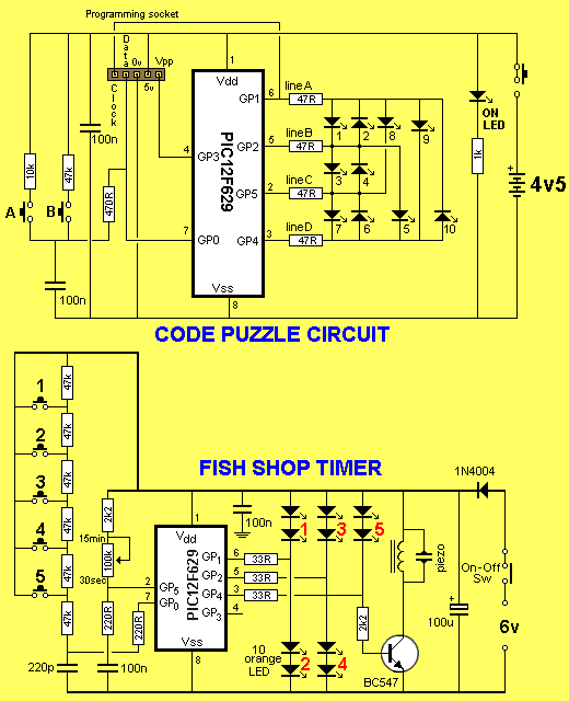
PROJECT 3
CODE PUZZLE
Two switches are used to turn on a LED. The switches must be pressed in
the correct sequence and at the correct time. To turn on the next LED,
the sequence is different. There are 10 LEDs and if the switches are
pressed incorrectly, one LED will go out.
PROJECT 3a
REACTION TIMER
This program uses the CODE PUZZLE PC board.
Call this a "Booze-O-Meter" or "Skill Timer" or "Reaction Timer," it's
all the same. Ten LEDs show the time taken to press the stop button
after an unknown delay period. You will be amazed at how your reaction
time increases when you are tired or after "drinking." Test your
friends.
PROJECT 3b
COUNT TO 1010
This program uses the CODE PUZZLE PC board. The 10 LEDs on the Code
Puzzle board are turned on as decimal values. The lowest LEDs blinks
every second. It is on for 0.5sec and off for 0.5sec) and after 10 seconds, the second LED illuminates
very dimply. After another 10 seconds its illumination is slightly
brighter. After illuminating 9/10ths of its brightness, it goes out and
the nest LED comes on dimly. All you
have to do is keep the project turned on and wait for the highest-value
LED to illuminate. It will represent 1010 seconds.
PROJECT 4
REMOTE CONTROL
Control a servo with a pot. This project opens up all sorts of remote
control applications such as panning and tilting of cameras, model
displays etc.
PROJECT 5
FOX HUNT
A surface-mount PIC chip is used to create a beep tone for an FM
transmitter.
PROJECT 6
TALK TO ME
Two identical TALK TO ME projects are placed in a room. One will emit a series of
chirps. The piezo diaphragm on the other is in "listening
mode" and if it hears the chirps, it will respond. The more
of these you have in a room, the more communication you will get. You
will have to see how the program works to appreciate the result you will
get.
PROJECT 7
SOUND "OFF"
A single button remote control to turn the sound on your TV on and off.
I have never listened to an advertisement in my life. I can't get to the
"off" button quick enough. Now you can have all the silence you want
during an advertisement. Just press the button and start to
think about the next project you will be working on. Silence is golden.
PROJECT 8
This project introduces you to creating sounds with the PIC chip. The chip comes pre-programmed with a doorbell chime but you can re-program it with any of the routines in the project and see how many effects can be produced.
PROJECT 9
CALL REMINDERHow many times have you tried to make a business call but the person did not answer?
Then you completely forgot to ring after say 30 minutes.
This is typical, as our mind finds it very difficult to repeat a particular action.
With this project you can set a reminder for any number of minutes and prevent this type of situation.
CALL REMINDER has a set of LEDs to indicate the number of minutes remaining before the mini piezo lets you know time is up.
This is just the beginning to the potential of the chip. After building one of the projects, you can change
any of the values in a sub-routine to see what effect it creates.
To do this, load the program into Notepad2.exe
(notepad2.zip) and
15/1/08