|
STEPPER MOTOR CONTROLLER |
|
|
This project controls a UNI-POLAR stepper motor in full and half-step increments.
Stepper Motor Controller
built on Experimenter PC board
THE STEPPER MOTOR
There
are a number of stepper motors on the market and it takes a little bit
of understanding to know how they work. The main difference is
the number of coils and the way they are connected but there are also
points to know to get the maximum torque .
A STEPPER MOTOR
A stepper motor consists
of a number of stationary coils and these are turned on and pull a
rotary magnet towards the coil. This action turns a shaft.
But you must turn the coils on and off at the right moment to create
rotary movement.
This requires an external circuit consisting of pulses and these pulses
must contain voltage and current to deliver energy to the stepper motor.
To understand how a stepper motor works, you just need to know the fact
that a coil will attract a magnet when a current flows and it will repel
the magnet when the current flows in the opposite direction.
In the following animation you can see an armature (rotor) being pulled
around by turning on one or more coils.

Note that 8 steps can be created with 4 coils by turning them on individually or in pairs:
Here is another diagram to show how the rotor is moved by half-step intervals:
UNIPOLAR
ANIMATION
The following animation shows a 6
wire stepper motor. It can be converted to a 5-wire stepper motor by
connecting the two centre taps together to the positive supply. The two
ends of each winding are alternately grounded to reverse the direction
of the field provided by that winding.
The cross section shown is a 30 degree per step motor. Motor
winding number 1 is distributed between the top and bottom stator pole,
while motor winding number 2 is distributed between the left and right
motor poles. The rotor is a permanent magnet with 6 poles, 3 south and 3
north, arranged around its circumference.
As shown in the figure, the current flowing from the center tap of
winding 1 to terminal "a" causes the top stator pole to be a north pole
while the bottom stator pole is a south pole. This attracts the rotor
into the position shown. If the power to winding 1 is removed and
winding 2 is energised, the rotor will turn 30 degrees, or one step.
By turning on two windings during part of the cycle, a half-step
can be introduced. This is shown in the animation.
It takes three complete cycles of the control system to turn this 6-pole
rotor one revolution.
HALF
STEPPING
With half stepping, the drive alternates between two phases ON and a
single phase ON. This increases the angular resolution, but the motor
also has less torque (approx 70%) at the half step position (where only
a single phase is on). This can be increased by increasing the current
in the active winding. Half-stepping increases the
accuracy of the output. This is what we have done in this project.
To keep the theory simple, we are not going into the waveforms needed
to produce rotation, however we need to explain how the coils are
connected as some motors have 5, 6 or 8 leads (wires).
4-wire stepper motors:
This type of motor has only one winding per stator pole.
This is called a
Unifilar winding (uni - meaning one). As we mentioned above, the winding
must see reverse voltage to produce rotation and this type of motor is
not covered in this project.
6-wire stepper motors:
6-wire stepper motors have two identical sets of windings on each stator pole. This is called bifilar winding and this type of winding configuration simplifies operation in that delivering current from one coil then another, wound in the opposite direction, will reverse the rotation of the motor shaft. Whereas, in a unifilar application, to change direction requires reversing the current in the same winding, as mentioned above.
5-wire stepper motors:
5-wire stepper motors simply have the centre-tap of each winding connected inside the motor or on a terminal-block.
8-wire stepper motors:
8-wire stepper motors simply have the wires from the two
coils brought out separately. This arrangement offers the flexibility of
either a series or parallel connection. But this will bring it to a
4-wire device and require voltage reversal to produce rotation.
You can also search the web for details on connecting the windings for high torque
but this is beyond the scope of this article.
The type of stepper motor we will be covering are
5, 6 or 8-lead Unipolar stepper motors.
UNIPOLAR AND BIPOLAR STEPPER MOTORS
A Unipolar Stepper Motor has two windings per phase, one for each direction of magnetic field. You can remember the word "Uni" means only one direction of current is needed for this type of motor. This is the type we use in this project.
A Bipolar Stepper Motor has a single winding per phase. The current in a winding needs to be reversed (thus the prefix "Bi" ) in order to reverse a magnetic pole, so the driving circuit must be more complicated, typically with an H-bridge arrangement.
The following diagrams show how to connect these stepper motors:
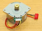
Here are 3 UNIPOLAR Motors that can be wired and used in this project:

Convert 6-Lead 5-Lead and 8-Lead Unipolar motors by following the
diagram above.
BIFILAR STEPPER MOTORS
To use a bifilar motor as a unipolar motor, the two wires of each
winding are connected in series and the point of connection is used as a
center-tap.
IDENTIFYING STEPPER MOTOR WIRES
If you do not have a schematic diagram for your stepper motor - for
example if it was salvaged from an old printer - it is very easy to work
out the wiring.
Bifilar windings on a stepper motor are applied to the same rotor and
stator geometry as a bipolar motor, but instead of winding each coil in
the stator with a single wire, two wires are wound in parallel with each
other. As a result, the motor has 8 wires, not four.
In practice, motors with bifilar windings are always powered as either
unipolar or bipolar motors.
To use a bifilar motor as a bipolar motor, the two wires of each winding
are connected either in parallel or in series. With parallel connection,
this allows low voltage high-current operation. With series connection,
if the center tap is ignored, this allows operation at a higher voltage
and lower current than would be used with the windings in parallel.
Essentially all 6-wire motors sold for bipolar use are actually wound
using bifilar windings. Any unipolar motor may be used as a bipolar
motor at twice the rated voltage and half the rated current on the
nameplate.
Most
stepper motors have
6 wires, however there are some with 4, 5, or
8 wires. Each of the four coils is made up of one length of wire
with two ends. One end is called live and
the other end is called common.
In a five-wire stepper motor all four commons
are joined together, in a six-wire stepper motor two pairs of common wires are joined together,
and in an eight-wire stepper motor none of the four common wires
are joined together.
The following diagrams show how the coils are connected:
Use a multimeter to measure the resistance of each coil. All four coils
will have identical resistance. If they did not, the motor would not
function properly. The resistance may be 100 ohms. If a pair of wires
measures 200 ohms, you are measuring between two live ends. In other
words, you are measuring the resistance of TWO COILS.
If you have a 5 wire stepper motor, it will be very easy to find the
common wire as every other wires will have a resistance of 100 ohms.
For the 6 wire stepper motor, you will have 3 wires with resistance
values and another 3 wires with resistance values. The two wires with
200 ohms resistance between them, are "live," so the other wire is
"common."
Once you have identified the "common" wire(s), you need to find the
correct "phases." This is another way of saying the correct way to
connect the motor so that it rotates clockwise of anticlockwise.
You cannot simply connect the "live" wires to the project in any order.
They must be connected so that the pulses will create a rotating
magnetic field.
There is no way to determine the correct way to connect a stepper motor
other than viewing the output on a 4-input CRO.
So, we have to do it by trial-and-error.
Connect the stepper motor in any arrangement to the project but make
sure the common goes to the positive rail, as we have already identified
this wire.
Turn on the project and see if the stepper motor rotates.
If not, do not touch the first wire. Simply swap the last two wires. If
this does not work, swap the 2nd and fourth wires. Then the second and
third wires.
The motor will not be damaged during this process as it does not take
any more current when oscillating back and forth or when rotating.
keep swapping the last three wires until the motor rotates.
PWM
To make a stepper motor rotate at the fastest RPM, we deliver a
pulse of very short duration, to each of the poles and the order of
delivering these pulses must be correct.
If we try to increase the RPM, we need to make the pulse shorter in
duration and a point will come when the stepper motor HALTS or STOPS or
FREEZES.
We now know the maximum RPM.
To decrease the RPM, we increase the length of each pulse and this
produces less pulses per second. The RPM decreases.
In all of this action, the stepper motor is taking almost the same
current as the voltage is being supplied almost constantly, the
only difference is the pulses are longer or shorter.
But suppose you want to supply less current or supply the stepper motor
with a higher voltage.
This can be done by delivering a short pulse then turning off the supply
for a short period of time between pulses.
This will not alter the RPM under the following conditions: Suppose the
minimum pulse-width is 5mS. Suppose the pulse-width is presently 25mS.
If the pulse-width is reduced to 5mS and an off-period of 20mS, the
stepper motor will retain the same RPM but consume less current.
The torque will also be reduced and this will have be checked - to see
if the motor stalls under load.
This action is called "reducing-the-pulse-width" and is commonly called
PULSE WIDTH MODULATION.
This is called "driving the motor with PWM."
You can also use PWM to drive a 12v stepper motor from 24v or 36v.
By using the example above, the stepper motor is only getting a pulse of
energy for 20% of the time, so that delivering a voltage such as 24v or
36v, will result in an average current that is less than driving it
without PWM on 12v.
These are the main reasons for using PWM. It is not used to control the
RPM.
STEPPER MOTOR VOLTAGE
You can find stepper motors in all types of consumer electronics,
including printers, video players, plotters and the head positioning motors from old diskette drives.
Most of these stepper motors are 12v.
However few of them are identified with the operating voltage and the
simplest way to test them is to connect to 12v and read the current.
Current consumption from 50mA to 300mA is quite common and since they
are generally used for very short periods of time, they will not get hot
or even warm.
If you want to use them on a higher voltage, such as 24v or 36v, you
will need to drive them with very short pulses and provide an off-period
in the waveform so that the overall current is not above about 300mA.
This involves a pulse-width technique called PWM, mentioned above.
This can be incorporated into the project by modifying the program.
|
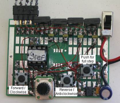
INSTRUCTIONS FOR
USE Turn the project ON and push the left button very quickly. The stepper motor will increment a half-step. Keep the button pressed and the stepper motor will rotate clockwise. Push the right button very quickly. The stepper motor will increment a half-step. Keep the button pressed and the stepper motor will rotate anti-clockwise. Push the top button. The project now goes to full-step mode. Push the left button and the stepper motor rotates clockwise in full-step mode. Turn the pot to increase or decrease RPM. Turn the project off. Push the top button. The project now goes to full-step mode. Push the right button and the stepper motor rotates anti-clockwise in full-step mode. Turn the pot to increase or decrease RPM. |
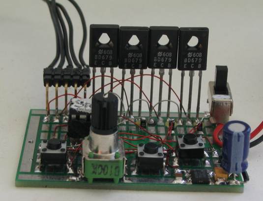
CONSTRUCTION
Stepper Motor Controller
16/11/2010
You can build the circuit on any
type of Proto board. We have chosen our surface-mount board as it makes
a neat project and you can see all the wiring at the same time.
The
PROGRAM
If you want to modify the program you will need a programmer, a board to
hold the 8 pin chip during programming and an adapter to connect between
the programmer and PC board.
These are
covered in our article "Pick-A-PIC."
Here are the files you will need for "burning" your chip and/or
modifying the program:
Step.asm
Step.txt
Step.hex
The following program is for viewing. It may contain
spaces or hidden characters that will not compile correctly to produce a
.hex file. Use the .hex file above to burn your chip or the .asm file to
modify the program.
;*******************************
;Stepper.asm
;drives a Stepper motor forward and reverse
;13-11-2010
;*******************************


	list	p=12F629
	radix	dec
	include	"p12f629.inc"

	errorlevel -302	; Don't complain about BANK 1 registers

	__CONFIG	_MCLRE_OFF & _CP_OFF
& _WDT_OFF & _INTRC_OSC_NOCLKOUT  ;Internal osc.

;_MCLRE_OFF  - master clear must be off for gp3 as input pin

;******************************
; variables - names and files
;*****************************

temp1	equ 20h	;
temp2	equ 21h	;

Sw_Flag	equ 25h	;switch flag for "inching"
loops	equ 26h ;loops for full stepping
count	equ 27h	;loops of discharge time for 100n
PotValue equ 28h ;value of pot
look	equ 29h ;look for pot value every 100 loops


;***************************
;Equates
;***************************
status	equ	0x03
rp1	equ	0x06
rp0	equ	0x05
GPIO 	equ 0x05


status		equ	03h
option_reg	equ 81h


		; bits on GPIO

pin7	equ	0	;GP0  100k speed pot
pin6	equ	1	;GP1  output1 to stepper motor
pin5	equ	2	;GP2  output2 to stepper motor
pin4	equ	3	;GP3  Input from buttons
pin3	equ	4	;GP4  output3 to stepper motor
pin2	equ	5	;GP5  output4 to stepper motor


		;bits

rp0	equ	5	;bit 5 of the status register

;**********************
;Beginning of program
;**********************
	org	0x00
	nop
	nop
	nop
	nop
	nop
SetUp	bsf	status, rp0 	;Bank 1
       	movlw	b'11001000'	;Set TRIS  GP1,2,4,5 out GP3 input
	movwf	TRISIO
	bcf	status, rp0	;bank 0
	movlw   07h         	;turn off Comparator ports
        movwf   CMCON       	;must be placed in bank 0
        clrf 	GPIO       	;Clear GPIO of junk
        clrf	Sw_Flag
        incf	Sw_Flag,1	;put a bit onto Sw_Flag
	goto 	Main


;****************
;delays		*
;****************

_uS	movlw	08Ch
	movwf	temp1
	decfsz 	temp1,f
	goto 	$-1
	retlw 	00


	;delay for pulsing servo anticlockwise

acw
	movlw	60h
	movwf	temp1
	decfsz 	temp1,f
	goto 	$-1
	retlw 	00


_1mS	nop
	decfsz 	temp1,f
	goto 	_1mS
	retlw 	00

_5mS	movlw	.5
	movwf	temp2
	nop
	decfsz 	temp1,f
	goto 	$-2
	decfsz 	temp2,f
	goto 	$-4
	retlw 	00


_10mS	movlw	0Ah
	movwf	temp2
	nop
	decfsz 	temp1,f
	goto 	$-2
	decfsz 	temp2,f
	goto 	$-4
	retlw 	00

_15mS	movlw	.15
	movwf	temp2
	nop
	decfsz 	temp1,f
	goto 	$-2
	decfsz 	temp2,f
	goto 	$-4
	retlw 	00


_18mS	movlw	.18
	movwf	temp2
	nop
	decfsz 	temp1,f
	goto 	$-2
	decfsz 	temp2,f
	goto 	$-4
	retlw 	00

_50mS	movlw	.50
	movwf	temp2
	nop
	decfsz 	temp1,f
	goto 	$-2
	decfsz 	temp2,f
	goto 	$-4
	retlw 	00


_100mS	movlw	.100
	movwf	temp2
	nop
	decfsz 	temp1,f
	goto 	$-2
	decfsz 	temp2,f
	goto 	$-4
	retlw 	00


_200mS	movlw	.200
	movwf	temp2
	nop
	decfsz 	temp1,f
	goto 	$-2
	decfsz 	temp2,f
	goto 	$-4
	retlw 	00


	;delay to create value for pot for speed

PotDel	movlw	040h		;40h produces 12 loops
	movwf	temp1
	decfsz 	temp1,f
	goto 	$-1
	retlw 	00


;***************************
; Sub Routines 		      *
;***************************


	;position of pot creates a value in PotValue

Pot	bsf	status,rp0
	bcf	trisio,0	;Make GP0 output
	bcf	status,rp0
	bcf	gpio,0		;make GP0 LOW
	call	_1mS	;create delay to discharge 100n
	bsf	status,rp0
	bsf	trisio,0	;Make GP0 input
	bcf	status,rp0
	clrf	PotValue
	call	PotDel
	incf	PotValue,f
	btfss	gpio,0		;is input HIGH?
	goto	$-3
	retlw	00	;returns with a value in PotValue


;******************
;* Main 	*
;******************

Main	clrf	gpio
	bcf	gpio,5	;gpio,5 high for a short time
	call	_1mS
	bsf	gpio,5
	nop
	btfss	gpio,3
	goto	$+2
	goto	$+6	;go to half step Forward
	clrf	gpio
	bsf		gpio,1
	btfss	gpio,3
	goto	Reverse	;go to half step Reverse
	goto	_FS      ;go to Full Step - for forward or reverse

	btfsc	Sw_Flag,0
	goto	_1HSF_
	btfsc	Sw_Flag,1
	goto	_2HSF_
	btfsc	Sw_Flag,2
	goto	_3HSF_
	btfsc	Sw_Flag,3
	goto	_4HSF_
	btfsc	Sw_Flag,4
	goto	_5HSF_
	btfsc	Sw_Flag,5
	goto	_6HSF_
	btfsc	Sw_Flag,6
	goto	_7HSF_
	goto	_8HSF_

_1HSF_	movlw	b'00100000'		;1
	goto	_C
_2HSF_	movlw	b'00110000'		;2
	goto	_C
_3HSF_	movlw	b'00010000'		;3
	goto	_C
_4HSF_	movlw	b'00010100'		;4
	goto	_C
_5HSF_	movlw	b'00000100'		;5
	goto	_C
_6HSF_	movlw	b'00000110'		;6
	goto	_C
_7HSF_	movlw	b'00000010'		;7
	goto	_C
_8HSF_	movlw	b'00100010'		;8
	movwf	gpio
	call	_200mS
	clrf	gpio
	call	_200mS
	call	_200mS
	clrf	Sw_Flag
	incf	Sw_Flag,1
	bsf	gpio,5
	nop
	btfsc	gpio,3	;see if sw is still pressed for full speed
	goto	HS_Fwd
	bcf	gpio,5
	goto	Main


_C	movwf	gpio
	call	_200mS
	clrf	gpio
	call	_200mS
	call	_200mS
	bcf	status,0	;clear the carry
	rlf	Sw_Flag,1
	bsf	gpio,5
	nop
	btfsc	gpio,3	;see if sw is still pressed for full speed
	goto	HS_Fwd
	bcf	gpio,5
	goto	Main


	;reverse - half step


Reverse
	clrf	gpio
	bcf		gpio,4	;gpio,4 high for a short time
	call	_1mS
	bsf		gpio,4
	nop
	btfss	gpio,3
	goto	Main

	btfsc	Sw_Flag,0
	goto	_1HSR_
	btfsc	Sw_Flag,1
	goto	_2HSR_
	btfsc	Sw_Flag,2
	goto	_3HSR_
	btfsc	Sw_Flag,3
	goto	_4HSR_
	btfsc	Sw_Flag,4
	goto	_5HSR_
	btfsc	Sw_Flag,5
	goto	_6HSR_
	btfsc	Sw_Flag,6
	goto	_7HSR_
	goto	_8HSR_

_1HSR_	movlw	b'00100000'		;1
	movwf	gpio
	call	_200mS
	clrf	gpio
	call	_200mS
	call	_200mS
	Movlw	80h
	movwf	Sw_Flag
	bsf	gpio,4
	nop
	btfsc	gpio,3	;see if sw is still pressed for full speed
	goto	HS_Rev
	bcf		gpio,4
	goto	Main

_2HSR_	movlw	b'00110000'		;2
	goto	_D
_3HSR_	movlw	b'00010000'		;3
	goto	_D
_4HSR_	movlw	b'00010100'		;4
	goto	_D
_5HSR_	movlw	b'00000100'		;5
	goto	_D
_6HSR_	movlw	b'00000110'		;6
	goto	_D
_7HSR_	movlw	b'00000010'		;7
	goto	_D
_8HSR_	movlw	b'00100010'		;8
	goto	_D


_D	movwf	gpio
	call	_200mS
	clrf	gpio
	call	_200mS
	call	_200mS
	bcf	status,0	;clear the carry
	rrf	Sw_Flag,1
	bsf	gpio,4
	nop
	btfsc	gpio,3	;see if sw is still pressed for full speed
	goto	HS_Rev
	bcf	gpio,4
	goto	Main


	;half step forward


HS_Fwd
	clrf	gpio
	bcf	gpio,5	;gpio,5 high for a short time
	call	_1mS
	bsf		gpio,5
	nop
	btfss	gpio,3
	goto	Main

	btfsc	Sw_Flag,0
	goto	_1HSF
	btfsc	Sw_Flag,1
	goto	_2HSF
	btfsc	Sw_Flag,2
	goto	_3HSF
	btfsc	Sw_Flag,3
	goto	_4HSF
	btfsc	Sw_Flag,4
	goto	_5HSF
	btfsc	Sw_Flag,5
	goto	_6HSF
	btfsc	Sw_Flag,6
	goto	_7HSF
	goto	_8HSF

_1HSF	movlw	b'00100000'		;1
	goto	_CC
_2HSF	movlw	b'00110000'		;2
	goto	_CC
_3HSF	movlw	b'00010000'		;3
	goto	_CC
_4HSF	movlw	b'00010100'		;4
	goto	_CC
_5HSF	movlw	b'00000100'		;5
	goto	_CC
_6HSF	movlw	b'00000110'		;6
	goto	_CC
_7HSF	movlw	b'00000010'		;7
	goto	_CC
_8HSF	movlw	b'00100010'		;8
	movwf	gpio
	call	_5mS
	clrf	gpio
	clrf	Sw_Flag
	incf	Sw_Flag,1
	goto	HS_Fwd


_CC	movwf	gpio
	call	_5mS
	clrf	gpio
	bcf	status,0	;clear the carry
	rlf	Sw_Flag,1
	goto	HS_Fwd


		;half step reverse

HS_Rev
	clrf	gpio
	bcf	gpio,4	;gpio,4 high for a short time
	call	_1mS
	bsf	gpio,4
	nop
	btfss	gpio,3
	goto	Main

	btfsc	Sw_Flag,0
	goto	_1HSR
	btfsc	Sw_Flag,1
	goto	_2HSR
	btfsc	Sw_Flag,2
	goto	_3HSR
	btfsc	Sw_Flag,3
	goto	_4HSR
	btfsc	Sw_Flag,4
	goto	_5HSR
	btfsc	Sw_Flag,5
	goto	_6HSR
	btfsc	Sw_Flag,6
	goto	_7HSR
	goto	_8HSR

_1HSR	movlw	b'00100000'		;1
	movwf	gpio
	call	_10mS
	clrf	gpio
	Movlw	80h
	movwf	Sw_Flag
	goto	HS_Rev
_2HSR	movlw	b'00110000'		;2
	goto	_G
_3HSR	movlw	b'00010000'		;3
	goto	_G
_4HSR	movlw	b'00010100'		;4
	goto	_G
_5HSR	movlw	b'00000100'		;5
	goto	_G
_6HSR	movlw	b'00000110'		;6
	goto	_G
_7HSR	movlw	b'00000010'		;7
	goto	_G
_8HSR	movlw	b'00100010'		;8
		goto	_G


_G	movwf	gpio
	call	_10mS
	clrf	gpio
	bcf	status,0	;clear the carry
	rrf	Sw_Flag,1
	goto	HS_Rev


		;decide on full step forward or reverse


_FS	clrf	gpio
	bsf	gpio,5
	btfss	gpio,3
	goto	$+2
	goto	FS_Fwd
	bsf		gpio,4
	btfss	gpio,3
	goto	$+2
	goto	FS_Rev
	clrf	gpio
	call	_1mS
	goto	$-10


	;Full Step Forward

FS_Fwd	call	pot		;returns with value in PotValue
	movlw	.50
	movwf	look	;look at pot every 50 loops
	movlw	b'00000010'		;full step forward
	movwf	gpio
	movf	PotValue,w
	movwf	loops
	call	_1mS
	decfsz	loops,1
	goto	$-2
	movlw	b'00000100'
	movwf	gpio
	movf	PotValue,w
	movwf	loops
	call	_1mS
	decfsz	loops,1
	goto	$-2
	movlw	b'00010000'
	movwf	gpio
	movf	PotValue,w
	movwf	loops
	call	_1mS
	decfsz	loops,1
	goto	$-2
	movlw	b'00100000'
	movwf	gpio
	movf	PotValue,w
	movwf	loops
	call	_1mS
	decfsz	loops,1
	goto	$-2
	decfsz	look,1
	goto	FS_Fwd+3  ;don't look at pot
	goto	FS_Fwd	;look at pot


	;Full Step Reverse

FS_Rev	call	pot	;returns with value in PotValue
	movlw	.50
	movwf	look	;look at pot every 50 loops
	movlw	b'00100000'	;full step reverse
	movwf	gpio
	movf	PotValue,w
	movwf	loops
	call	_1mS
	decfsz	loops,1
	goto	$-2
	movlw	b'00010000'
	movwf	gpio
	movf	PotValue,w
	movwf	loops
	call	_1mS
	decfsz	loops,1
	goto	$-2
	movlw	b'00000100'
	movwf	gpio
	movf	PotValue,w
	movwf	loops
	call	_1mS
	decfsz	loops,1
	goto	$-2
	movlw	b'00000010'
	movwf	gpio
	movf	PotValue,w
	movwf	loops
	call	_1mS
	decfsz	loops,1
	goto	$-2
	decfsz	look,1
	goto	FS_Rev+3  ;don't look at pot
	goto	FS_Rev	;look at pot

	END
GOING
FURTHER
You can add additional features to this
project by writing your own program or modifying the program above.
Parts List
Cost:
au$25.00
plus postage
Kits
are available
1 - 39R SM resistor>
4 - 100R SM resistor
1 - 220R SM resistor
3 - 2k2 SM resistor
1 - 47k SM resistor
1 - 100k pot
2 - 100n SM capacitors
1 - 100u electrolytic
4 - SM yellow LEDs
1 - SM diode
4 - BD679 transistors
1 - 78L05 SM voltage regulator
1 - SPDT mini slide switch
3 - mini tactile buttons
1 - 8 pin IC socket
1 - 5 pin header
40cm fine enamelled wire
20cm fine tinned copper wire
20cm - very fine solder
1 - PIC12F629 chip (with
Step routine)
1 - 4-cell battery holder
1 - battery snap
1 - Prototype PC board