|
|
|
|
Turn the 2-Digit Up/Down Counter into a remote-controlled
counter by adding this RF link.
This section describes an RF
link consisting of a 4 channel transmitter on a small PC board and a
receiver on another small PC board that connects to the
Up/Down Counter.
The 4 buttons are:
Up,
Down,
Reset the number on the display and
Toggle the display On/Off.
The Up/Down Counter circuit
can be seen on P3 of this article and uses a PIC12F629
to drive 28 SM LEDs arranged as two 7-segment displays.
This RF link can be used separately however its output consists
of 4 frequencies: approx 500Hz, 550Hz, 660Hz and 1kHz
and these have to be decoded (detected by a "detection circuit" or by
the software in the PIC micro) so that each frequency turns on a
particular output. If you don't use our PIC micro (and the program in
it), you will need to design a fairly complex circuit to
decode these frequencies and produce individual outputs.
THE LAYOUT
When working with RF circuits (anything above about 1MHz), you have to
be careful with the layout if you want the circuit to have the same
frequency as shown on a circuit diagram and have the same performance (such as
range and stability).
As the frequency gets higher, the length of the leads of the
components have an effect on the performance and also the frequency.
There is also another thing to remember.
For a circuit to "push" energy into an antenna, it must have a firm
base.
Look at it this way. You are standing on a trampoline and want to throw
a bowling ball (a very heavy ball) into a netball hoop. As you try to
throw it up, you sink into the trampoline and it will be very difficult
to "score."
The same with a transmitter circuit.
As the circuit tries to push energy into the antenna, from say an
inductor, the other end of the inductor must be held rigid, otherwise
the energy will go out both directions and very little will be "sent
to
the antenna."
This means you need to have a good ground plane and this means
keeping everything tight, through the power leads, to the
battery as the battery will provide the major part of the ground plane.
We have used surface-mount components in this project and this creates a
very tight circuit due to the minüte nature of each of the components.
If you use ordinary leaded components on a prototype board, the
frequency and performance may be different to our design.
The fact that SM components are very small and close together produces a
higher frequency and higher output. This is something you have to
remember.
A transmitter circuit is fairly easy to design and test as you can
easily detect the output frequency.
But a receiver is more difficult. Sometimes you can match the oscillator
components in the receiver with those of the transmitter, but the actual
frequency of oscillation depends on all the surrounding components and
that's why the coil values are different in the transmitter and
receiver.
After a lot of experimenting, we chose the receiver circuit shown in the
diagram. Some receiver circuits did not detect the transmitter, even
though the receiver was tuned to the correct frequency.
Getting an RF link to work is much more complex than you think.
That's why you have to build the circuits shown in the diagrams.
We have chosen 27MHz so you can test the transmitter by using a simple
27MHz Walkie Talkie as a piece of test gear.
This will allow you to get the transmitting frequency correct and from
there you can build the receiver.
THE ANTENNA
Nothing beats a long antenna, such as a full-wave antenna, but if space
is limited, a "cut-down" version has to be used.
While specially designed "half-wave, quarter-wave" etc antennas are nearly as good as a simple piece of "long
wire," they are more expensive and need skill to design and get working
correctly.
We added an inductor (such as those on simple walkie-talkies) to the antenna of the transmitter and also
the receiver and tried every combination.
We achieved exactly the same range as a straight piece of wire.
I am not saying the inductor will not work in some instances, but it did
not increase the range in our prototype.
Now we come to the point of this discussion.
The length of the antenna is important. It determines range.
A full-length antenna for 27MHz is approx 11 metres long, so any antenna
shorter than this is going to have a "mis-match" and not be fully
efficient. The 30cm antennas we are using are highly inefficient and
that's why increasing the length, increases the range appreciably.
Our tests showed that increasing the length by 50%, increased the range
over 200%.
THE TRANSMITTER
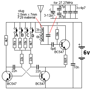
4-Channel 27MHz Transmitter
The transmitter consists of three transistors in two building-blocks.
The first section is the multivibrator that is turned on when one of
four buttons is pressed.
These buttons determine the frequency of oscillation as they provide the
timing current for the two 22n capacitors. The operation of a
multivibrator has already been covered in our Electronics Course (buy CD
of whole site for more details) and basically one transistor is fully
turned ON while the other is fully OFF and the two swap conditions very
quickly. When the right-hand transistor is turned on, it takes the 56R
to the negative rail and this turns on the RF stage.
The tuned circuit made up of the tapped coil (and capacitor across it),
gets a jolt of current via the 3 turn winding and this sets it in
oscillation.
Exactly how it gets this jolt is fairly complex. The emitter of the RF
oscillator transistor is taken to 0v and the base is turned on via the
39k. This causes the transistor to draw current via the collector. The
collector current flows through the 3t winding and this produces flux in
the core of the slug. The flux cuts the 6t winding and a voltage is
produced by this winds (as well as the voltage across the 3t) to deliver
a voltage across the capacitor. At the same time a small amount of the
voltage is passed to the base of the transistor via the 4p7 to turn the
transistor on more.
This causes more current to flow in the 3t and and the process
increases. All this happens in less than a microsecond and a point comes
when the transistor cannot turn ON any more with the amount of energy
being supplied by the 4p7. The current does not increase though the 3t
winding but remains steady at a DC level and the flux in the core
changes from expending flux to stationary flux.
Stationary flux does not deliver a voltage to the 6t winding and the
voltage from this winding ceases. This means the energy delivered to the
transistor via the 4p7 ceases.
This turns the transistor off slightly and the current through the
collector circuit reduces. This causes a reduced current to flow in the
3t and now the flux in the core becomes a contracting flux. This puts a
voltage on the 6t winding that is in the opposite direction to
previously and now the voltage on the base of the transistor is less
than before and the transistor turns off more.
This causes less current to flow in the collector circuit and the
condition continues until the transistor cannot turn off any more via
the energy from the 4p7. The capacitor across the coil gets charged
during the fist parts of the cycle and the rate at which it charges
creates a length of time. And the time it takes to discharge and charge
in the opposite direction creates the first half cycle. The time
it takes to discharge and charge in the opposite direction creates the
second haft cycle.
The frequency of oscillation depends on the inductance of the coil and
capacitance of the capacitor across it.
The fixed capacitance is actually 36p and this was made up of a number
of surface mount capacitors as these were the only values available. You
could use 33p or 39p.
No on-off switch is required as no transistor consumes any
current when the base of the two multivibrator transistors are not
connected to the positive rail.
The way the circuit works is this:
When the right-hand transistor in the multivibrator turns on, the RF
stage turns on and produces a "Carrier." This is a signal with a
frequency of 27MHz. This is picked up by a receiver as "quiet." In other
words, the background noise is removed and the output is
silence.
When the RF stage is turned off, the background noise is detected.
In other words it is the background noise that is detected and not any
actual tone. We turn the background noise on and off and this is detected
by the receiver.
THE RECEIVER
The receiver is a module connected to the 2-Digit Up/Down counter. The
PIC12F629 microcontroller does all the work of decoding the 4 individual
frequencies and produces a result. 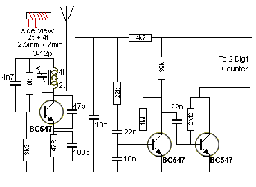
27MHz Receiver
The receiver is a very clever design.
It is actually a transmitter - a very weak transmitter and it
sends a signal to the surroundings. When a signal of the same frequency
is present in the surroundings, the stage finds it harder to transmit
its signal and a higher current is taken by the stage.
This increase causes a voltage drop though the 4k7 load
resistor and thus an amplitude is produced at the point where the 22k
has been connected.
The amazing thing is the circuit needs the 10n capacitor to operate
correctly and when it is set up, a waveform can be clearly detected
through the 22k resistor.
The 22n is a coupling capacitor and the 10n on the base of the second
transistor removes more of the "hash" (noise) from the received signal.
All this attenuation reduces the wanted signal and we need another stage
to amplify the signal to a point where it is large enough to trigger a
microcontroller. The third transistor has been biased ON very lightly by
the 2M2 base resistor and this allows the transistor to provide a large
amplitude.
The winding of the oscillator coil is very critical as even half-a-turn
will change the frequency at which the circuit wants to operate and you
will never be able to pick up the transmitter.
Obviously all the parts for commercial walkie-talkies are pre-made
to strict tolerances and that's why they work when tested.
When you are copying a design with your own components, it is important
to get everything as close as possible to the original, to be sure it
will work.
I could say the rest of the components are not critical but that is not
true. At first glance you would think the values could be changed but if
you want the sensitivity we achieved from the prototype, you need to use
the same values.
The signal from the receiver is passed to the PIC microcontroller where
it looks for a HIGH from the receiver then looks for a LOW and then a
HIGH. If this is detected within a time-frame, the program considers a
signal is present and it repeats the detection, taking more-accurate
measurements.
The signal processing is done while one of the displays is illuminated
and thus the detection does not interfere with the illumination of the
display.
The four buttons are:
Up
Down
Reset the number on the display
Toggle the display On/Off
According to the frequency of the signal, the program will execute an
outcome.
CONSTRUCTION
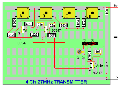
Construction of this project is not for beginners. The parts
are placed on a prototype board and you need to be competent at
soldering as well as being able to work out the placement of the
components. We have provided a layout diagram and this needs to be
followed carefully to avoid making a mistake.
Soldering surface-mount components is not easy and the biggest problem
is identifying the capacitors. They are not marked and the size of the
component is no indication of their value.
The capacitors have been placed in a strip with a black band at one end.
This indicates the lowest value then they increase in value according to
the diagram shown below.
Remove one component at a time and solder it in place so you don't get
any mixed up.
Use a very fine tipped constant-temperature soldering iron set to 360°C
and the fine solder supplied in the kit.
The
The surface mount capacitors are not
identified in any way. They are supplied in a strip with a black strip
at one end and this indicates the lowest value.
The files:
PARTS LIST
TRANSMITTER
RECEIVER To order the kit,
send
an email
to us and we will reply with the details of how to order
etc.
Take one capacitor from its carrier and fit it to the board before
removing the next.
Some capacitors are large and others are very small but the size is no
indication of the value.

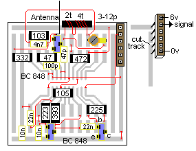
The
receiver is built on a 20 pin surface mount PC board but almost any
board will be suitable.
The power for the circuit comes from the 2-Digit Up/Down counter module
and the signal generated by the receiver board is passed to the PIC chip
for processing.
The collector load resistor for the second AF amplifier is fitted to the
2-Digit Up/Down counter module.
The only component that need careful attention is the oscillator
transformer. Even though it appears as a single winding, since it is
centre-tapped, it has a turns-ratio between the collector circuit and
the base circuit and its overall inductance needs to be accurate so the
circuit will oscillator at 27.2MHz. We already explained the fact
that the circuit is a very weak oscillator and when the same frequency
is present in the surroundings, the current taken by the circuit will
change and this is passed to the Audio Frequency stages for
amplification.
The surface mount capacitors are not identified on the components. They
are supplied in a strip with a black strip at one end and this indicates
the lowest value.
Take one capacitor from its carrier and fit it to the board before
removing the next.
Some capacitors are large and others are very small but the size is no
indication of the value.

Connecting the receiver to the 2-Digit
Counter
The two buttons on the 2-Digit Up/Down counter module are not used when
the receiver module is connected via the 5-pin plug-and-socket
arrangement.
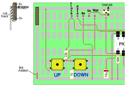
2 Digit Up/Down
Counter and 6-pin connector
12F629Counter.asm
12F629Counter.hex
12F629Counter.txt
12F629Counter-h.txt
NotePad2-exe
NotePad2.zip
MPASM - this file comes on the CD with PICkit-2
PICkit-2 - this "burning" or "programming program" on the CD with
PICkit-2.
The program below is the assembly program. This is for viewing ONLY. To
modify the program you will need to load
this file:
12F629Counter.asm into NotePad2
and make the changes.
The .asm is then compiled via MPASM to produce a .hex file for PICkit-2.
Set up your desktop as follows, with a folder called PICkit-2 files.
Inside this folder you can have other folders such as PIC12F629 Counter;
then an icon for MPASM and an icon for PICkit-2:![]()
	;2Digit Counter   12F629.asm
	;  13-6-2009


status
	retlw 	00

show03
	bsf	status, rp0 	;Bank 1
       	movlw	b'00010001'	;Set TRIS  to show seg A & C
	movwf

show80
	bsf	status, rp0 	;Bank 1
       	movlw	b'00100000'	;Set TRIS  to show seg A & C & E
	movwf	TRISIO
	bcf	status, rp0	;bank 0
	movlw	b';unit display value will return in w
	movf	tens,0		;copy tens value into w
	call	table2		;tens display value will return in w
	bsf	status, rp0 	;Bank 1
       	movlw	b'11111101'	;Set TRIS
	movwf	TRIS;Clear Up repeat flag
	clrf	FastCount
	goto	Main

		;oscillator calibration
	call 	03ffh
	movwf	OSCCAL

	end
for RF Link
RESISTORS
(All surface mount 1/10th watt)
1 - 56R marked as 470
2 - 4k7 "
" 472
1 - 15k "
" 152
2 - 22k " " 223
2 - 39k " " 393
1 - 56k " " 563
CAPACITORS
1 -
3-12p air trimmer
4 - 4p7
2 - 47p
1 - 10n surface mount
2 - 22n surface mount
SEMICONDUCTORS
3 - BC847 - surface mount (1F)
20cm - 0.5mm wire for antenna
1 - 2.5mm x 7mm F29 slug
20cm - 0.28mm enamelled wire
10cm fine tinned copper wire
4 - tactile switches
1 - 30cm fine solder
1 - 4 AAA cell battery box
Experimenter PC Board
RESISTORS
(All surface mount 1/10th watt)
1 - 47R marked as 470
1 -
3k3 "
" 332
1 - 4k7
"
" 472
1 - 10k
"
" 103
1 - 22k " " 223
1 - 39k " " 393
1 - 1M "
" 105
1 - 2M2 " "
225
CAPACITORS
1 -
3-12p air trimmer
1 - 47p surface mount
1 - 100p surface mount
1 - 4n7 surface mount
2 - 10n surface mount
2 - 22n surface mount
SEMICONDUCTORS
3 - BC847 - surface mount (1F)
4 - 5 machine pins on strip
30cm - fine solder
20cm - fine enamelled wire
20cm - 0.5mm wire for antenna
1
- 2.5mm x 7mm F29 slug
20cm - 0.28mm enamelled wire
10cm fine tinned copper wire
Experimenter PC Board (20pin SM PC)
GOING FURTHER
You can change the function of any
button by creating a sub-routine and calling it when the
button is detected.
If you have any questions on how the circuit works or how to
add different features,
email
the author and your answer will
be posted here:
The next page describes the up/down counter displaying the "gear" for
motorcycles and racing cars.
10/9/09
