|
|
|
|

The Up/Down Counter described on the
previous 4 pages can be configured
to display the "gear" for
racing bikes and cars. It can be configured as: 1- 6 gears or 1- 9
gears. This project it has been configured as 1- 6 gears suitable
for cars with "electronic" gear- shifts
- where the gear-shift is pressed forward to change up and press
back to change down.
These gear-boxes can have 6 gears and since they don't
have a read-out, it is sometimes difficult to remember which gear
you are in.
This project solves that problem.
There are two circuits.
Circuit 1 uses a PIC12F629 and a special arrangement of LEDs to
produce a display. Circuit 2 uses a PIC16F628 and a 7-segment
display.
Circuit 3 uses a PIC12F629 and 4 LEDs to show gears 1,2,3,4.
CIRCUIT 1:
The circuit is very similar to the 2-Digit Up/down
Counter on P1 and is constructed
on proto-type PC board for easy modification.
Mr R Cermak wanted a counter for his bike with the following features:
PARTS LIST
RESISTORS To order the kit,
send
an email
to us and we will reply with the details of how to order
etc. Up/Down Counter using
PIC16F628 and
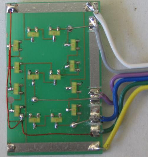
CIRCUIT 2:
Here is a PCB layout for circuit 2 produced
by one of our readers, Nick Holas,
wendyys81@hotmail.fr
Here are the files for the PIC16F628 circuit
2:
R_CermakPIC16F628.asm Up/Down Counter using
PIC12F629 and CIRCUIT
3:
This version of the car gears up/down
counter uses 4 LEDs. CarGears1-4.asm
100n capacitors can be placed across each switch
When the project is first turned on, the display shows "0." When the
gear-change is pressed in the up direction, the counter increments. It does not go past
"6." If the bike is in 6th gear and the gear-change is pressed up,
the counter does not increment.
In addition, the counter only decrements to "1."
If the counter gets out of synchronisation, the RESET button is
repeatedly pressed and this makes the display show: 0-1-2-3-4-5-6.
That's why it is called "RESET / CYCLE 0-6." 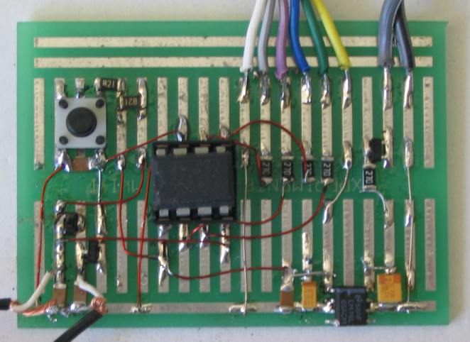
For 12v use, a 5v regulator such as 78L05 has been included. The kit
comes with a pre-programmed PIC12F629 and all components for assembly on
a proto-type PC board using 14 yellow LEDs. The display is 30mm high and
can be separated from the board containing the PIC chip for easy placement on the dashboard.
The program is very simple and has just three sub-routines, Up, Down and
Reset.
In Main, the program detects one of three switches, using two
inputs. The Down button takes both inputs LOW while the Up and Reset
buttons take only one line LOW. It takes only 6 lines of code to produce
an outcome. Firstly the Reset (or Cycle) button is polled. If GP0 is
LOW, we need to check if the other input (GP3) is LOW before we can make
a decision. If GP3 is not LOW, Reset has
been pushed.
If GP3 is LOW, Down has been pressed.
Now we go back to the first line of code where we polled the Reset
button. If GP0 is not LOW but GP3 is LOW, the Up button
has been pressed. Here are the 6 lines of code, starting at btfsc GPIO,0
	;Car Gears Up/Down Counter   12F629.asm


Main	bsf	status, rp0 	;Bank 1
       	movlw	b'11111101'	;Set TRIS  to detect switches
	movwf	TRISIO	   	; GP0&GP3=in
	bcf	status, rp0	;bank 0
	btfsc	GPIO,0
	goto	$+4 		;goto XX as reset not pushed
	btfss	GPIO,3		;reset or down pushed
	goto	Down		;down pushed
	goto	Reset		;reset pushed
	btfss	GPIO,3		;XX
	goto	Up		;up pushed
	clrf	Sw_Flag		;nothing pushed
M1	movf	count,w
	call	table
	goto	Main
When the project is turned on it starts with "0" on the display.
The Down button does not function when "0" is displayed.
The Up button only increments to 6. The down button only decrements to
"1."
The Cycle button increments to 6 then displays "0,1,2,3,4,5,6." These
"stops" or "limits" are created in the Up Down and Reset sub-routines
by comparing the "count" file with a value such as 6, 0 or 1.
The Display uses 14 yellow LEDs and have a characteristic voltage-drop
of 1.9v When 4 LEDs are placed across the supply, they require
7.6v and thus they will not illuminate on a 5v rail.
But if one of the outputs of the PIC chip is connected to the mid point
of the LEDs, the two lower LEDs will illuminate when the output is HIGH
and the two top LEDs will illuminate when the output is LOW. This is how
we activate two segments from a single output line.
By rapidly changing the output LOW, HIGH, LOW etc, we can illuminate two
segments at the same time.
Here are the files:
Car.asm
Car.txt (asm)
Car.hex
Car-h.txt (.hex)
The counter comes on with "0"
Down is pressed for "1" then Up for 2,3,4,5,6.
If Up is pressed at the beginning, display shows 2.
The following files are for his features and uses Circuit 1:
Bike Gears -2.asm
Bike Gears -2 .hex
(for 1- 6 gears)
$25.00 plus $5.00 postage
(All surface mount 1/10th watt)
5 - 22R marked as 220
2 - 1k "
" 102
CAPACITORS
4 - 100n surface mount
1 - 1u tantalum "105"
1 - 10u tantalum "106"
SEMICONDUCTORS
1 - 78L05 regulator - SM
1 - 1N4148 diode - SM "a6"
1 - PIC12F629 Micro (0-6 Counter)
3 - tactile switches
1 - 8 pin IC socket
14 - yellow LEDs for display
30cm - fine solder
20cm - fine tinned copper wire
50cm - 0.025mm enamelled wire
1 -
up/down counter
PC board
(Experimenter Board)
7-segment Display
When power is applied, the counter quickly cycles:
‘0,1,2,3,4,5,6,0,’ and ends with ‘0’ ready for
pressing of any switch.
Down is pressed for "1" then Up for 2,3,4,5,6. If Up is
pressed at the beginning, display shows 2.
Reset cycles:
‘0,1,2,3,4,5,6,0,’ and ends with ‘0'
A HIGH on "HIGH INPUT" dims the display to 50%
brightness. 
PCB layout from
Nick Holas:
wendyys81@hotmail.fr
R_CermakPIC16F628.hex
4 LEDs
There are many different possibilities and the .asm file has
been included to show how the program is laid out.
It can very easily be extended to any number of gears.
CarGears1-4.hex
If you have any questions on how the circuit works or how to
add different features,
email
the author and your answer will
be posted here: