5x7 Display
Construction Part
1
Part 1: The circuit diagram
Part2: The 5x7
"In-Circuit" Programmer

|
 |
|
|
| Click
to enlarge |
Click
for large
view of PC Board |
Click
for very large
view of PC Board |
THE CIRCUIT
The circuit for the 5x7 Display project is shown
below. This project also contains an "in-circuit" programmer as shown on the
next page. Both circuits are combined on the PC board but they have been
shown separately to keep things as simple as possible.
HOW
THE CIRCUIT WORKS
The circuit relies on a program in the PIC16F84 chip to activate the LEDs
and piezo diaphragm.
This program is "Burnt" into the chip during
"Programming" or "Burning" or "Downloading."
Without a program, the circuit does nothing.
Depending on the complexity of the program, the LEDs will display
different effects. This is fully covered in the "Testing"
"Experiments"
and "Piezo
Experiments" sections.
Only one column of LEDs is shown in the
diagram above. The full set of 35 LEDs is shown in the diagram below:
Only one column of LEDs turns on at a time. Seven
of the lines of port B drive the LEDs via 100R resistors and the
cathodes are connected together and taken to the 0v rail via a
"sinking" transistor.
The 5 sinking transistors are turned on (one at a time) by the outputs
of a CD 4017 "counter" chip.
This chip has 10 outputs with one output going
HIGH at a time. The chip is firstly reset by taking pin 15 HIGH then LOW
and keeping the line low - this allows the chip to "clock."
The first output (pin 3) goes HIGH and this is connected to the first transistor
via a 2k2 base resistor. The transistor turns on and the cathodes of the first column of LEDs
connect to the 0v rail.
The LEDs are turned ON by delivering current from the PIC chip. When any of the output lines of the chip go
HIGH (RB0 to RB6), the corresponding LED(s) are illuminated. The 100R resistor limits the
current to about 25mA as this is the maximum each output is designed to
deliver.
The output lines of the chip correspond to Port B (file 06) and by
turning off these lines, clocking the 4017 then turning on the outputs
again, the second column of LEDs will be illuminated. This is repeated
for the 3rd, 4th and 5th columns. When this is repeated at a rate above
50 times per second, the whole screen of LEDs appears to be ON at the
same time. This is how a picture or effect is
produced on the screen - it's called scanning.
The 8th line of output port B (RB7) is connected to a driver transistor.
This transistor is connected to a piezo diaphragm and two output pins
are provided on the board to drive a 5v relay or globe, instead of the
piezo.
The project includes a 1k resistor as a load resistor for the driver
transistor but a 10mH choke can be placed across the piezo to increase
the output.
Three switches are provided on the board (SwA, SwB and SwC). When these
switches are pressed, they provide a HIGH on the corresponding input
line. The PIC chip must be programmed so that port A, (bits 2, 3 and 4)
(RA2, RA3 and RA4) are inputs.
The 220R resistors connected in series with the switches prevent damage
to the chip. If the output is programmed to be LOW and the switch is
pressed, a high current will flow into the chip if a resistor is not
included. The 10k resistor is a voltage divider with the 220R to allow a
HIGH to be produced when the switch is pressed. When the switch is not pressed, the
10k provides a LOW to the input line.
The PIC chip has an internal oscillator that requires either a crystal
or resistor/capacitor components to be fitted to determine the frequency
of oscillation.
A 4k7 resistor and 22p capacitor will produce very close to 4MHz.
The chip can be clocked at DC (called single-step mode) or as high as
4MHz.
A power diode on the supply line drops the 6v to about 5.4v as the PIC
chip requires a voltage below 5.5v. The diode also serves as reverse-voltage protection.
The 100n across the chip prevents high-frequency instability and the
100u electrolytic removes ripples on the supply line.
|
5X7
PARTS LIST
Cost:
au$59.90 plus postage
| |
8 - 100R 1/4 watt
3 - 220R "
3 - 1k
7 - 2k2 (1 inside D-plug)
2 - 4k7
5 - 10k
1 - 22k
2 - 18p NPO ceramic
1 - 22p NPO ceramic
1 - 100n monolithic capacitor "monoblock"
1 - 2u2 16vw electrolytic
1 - 100u 16vw electrolytic
36 - 3mm red LEDs
1 - 3mm green LED
2 - 1N4148 signal diode
1 - 1N 4004 power diode
1 - 6v2 400mW Zener diode
1 - 4MHz crystal
8 - BC 547 transistors or similar
1 - BC 338 transistor or similar
1 - mini PCB piezo diaphragm
2 - SPDT mini slide switches
1 - DPDT mini slide switch
4 - PC mount tactile push switches
1 - red screen 3cm x 4cm
1 - 4-pin US telephone socket (low profile)
(RJ12 6P4C
PCB socket)
1 - 4-pin US plug on 2metres 4-core cable
( RJ12 6P4C crimp
plug on 2m 4 core flat
telephone modular cable)
1 - 9 pin D-type socket
1 - 9 pin backshell
1 - 50cm fine tinned copper wire
1m - very fine solder
1 - 16pin IC socket
2 - 18pin IC socket (put PIC chip in one!)
1 - CD 4017 decade counter
1 - PIC16F84 chip (with Test Routine)
4 - 10mm flat rubber feet
1 - 4-AA cell battery holder
4 - AA cells
1 - 5x7 Display PC board
| |
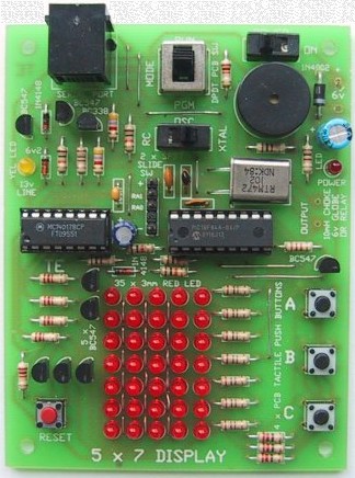
FITTING
THE COMPONENTS
When all the LEDs on the 5x7 display have been fitted, the other components
can be added to the board. It does not matter if you start from one side
of the board and add each component as you come to it or fit one type of
component at a time.
The only important point is remembering to fit the transistors, diodes
and electrolytics around the correct way. Make sure you do not get the
6v2 zener mixed up with the signal diode.
All the other items are clearly marked and the BC 338 has the same
pin-out as the BC 547 transistors. The chips are mounted in IC
sockets. This makes them easy to remove and test if a fault
develops. The IC sockets have a "cut-out" at one end to
identify pin 1. The crystal, ceramic capacitors, and slide switches
can be mounted around either way.
The push switches must be mounted around the correct way. See the diagram
below to see how they are fitted:
A small piece of red screen is placed over the LEDs to improve the effectiveness
of their emission.
CONNECTING
THE 5x7 TO A PC
 The
5x7 Video Display connects to a PC via a 4-pin US telephone plug and a 9-pin D-plug.
The actual colours of the wires in the cable will depend on how it is crimped to the
4-pin telephone plug however the diagram on the left shows how to wire the 9-pin
D-plug.
The
5x7 Video Display connects to a PC via a 4-pin US telephone plug and a 9-pin D-plug.
The actual colours of the wires in the cable will depend on how it is crimped to the
4-pin telephone plug however the diagram on the left shows how to wire the 9-pin
D-plug.
TESTING THE
DISPLAY
When all the LEDs, transistors, switches, resistors IC sockets and all
other components have been fitted, the LED display should be tested to make
sure all the LEDs are working.
there are 3 possible causes for a LED not to illuminate.
1. Dry joints on the underside of the board,
2. LED fitted around the wrong way, and
3. Soldering-time too long or the soldering iron too. LEDs can easily be
damaged by excessive heat and this will cause their brightness to be
reduced.
Set-up a very simple piece of test gear by connecting a 470R resistor to a
battery-snap and a stiff wire (cut from a resistor) to the other lead.
Place the positive probe on the 100R resistor and the negative lead on one
of the collectors. One of the LEDs should illuminate. Try each of the 100R
resistors and all the LEDs in a column should illuminate.
Repeat with the collectors of the other transistors.
Replace any faulty or weak LEDs as the display must have uniform
brightness.
THE CRYSTAL
OSCILLATOR
The 5x7 Display project uses a Resistor/Capacitor (R/C) network for the
microcontroller oscillator so that the chip operates at approximately 4MHz.
This frequency is not critical and so non-accurate components can be
used.
During burning, the chip can be programmed for one of four different types
of oscillators (Crystal, Resistor/Capacitor, Low-power crystal - such as
38kHz watch crystal - or HS). If Crystal is selected (such as 4MHz),
the chip will not work if Resistor/Capacitor components are connected to the
"clk in" pin. The same applies if RC is selected during
programming. The chip will not work if a crystal is connected to pins 15 and
16.
Once you know this, you will not fall into this trap.
If you are producing a program for notes and tunes you will find it handy to
be able to design with an accurate crystal frequency, then convert to RC
components in the final production-run.
The circuit below shows how to switch between RC and Xtal.
THE CERAMIC
RESONATOR
The 5x7 Video Screen project can also be fitted with a ceramic resonator in
place of a crystal. They are much smaller and cheaper than crystals and some
have an inbuilt load caps. Ceramic resonator type CST4.00MGW from
Farnell 295-346 has inbuilt capacitors as shown in the diagram below. A
two-pin resonator is placed between pins 15 and 16.
THE RESET CIRCUIT
During the design of the 5x7 Display project we had a slight problem getting the
circuit to start-up every time the on/off switch was turned ON. The chip was
not resetting properly and nothing appeared on the display, or it came on in
a "frozen" state. This only
occurred with some chips and luckily we came across a "problem
chip." The answer was to include an AUTOMATIC RESET CIRCUIT as
shown below:
This circuit delays the
voltage to the MCLR line so the chip sees a low on this line during start-up.
RESETTING
The micro can be reset without having to turn off the power, by taking the MCLR line
low via a switch. The Reset switch on the PC board does this.
Go to the next
page:
Construction - Part 2 (The "In-circuit Programmer" section of
the 5x7 project)