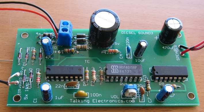
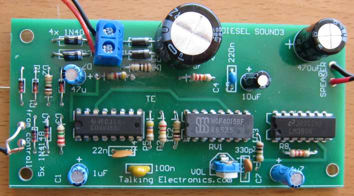
Save 75 Model
Railway Projects: .doc
(18MB) or .pdf (11MB)
17-4-2023 17-4-2023023023023023023023023023023023023023023023
Our other free
eBooks,
50
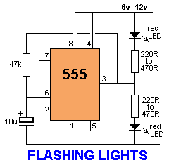
- 555 Circuits
1 - 100 Transistor Circuits
and: 101 - 200
Transistor Circuits
100 IC Circuits
Talking
Electronics has produced two books on Model Railway Electronics.
They are
Electronics
for Model Railways-1 (pdf) and
Electronics
for Model Railways-2 (pdf)
These books have completely sold out so we have provided them in .doc format
(Word) and .pdf
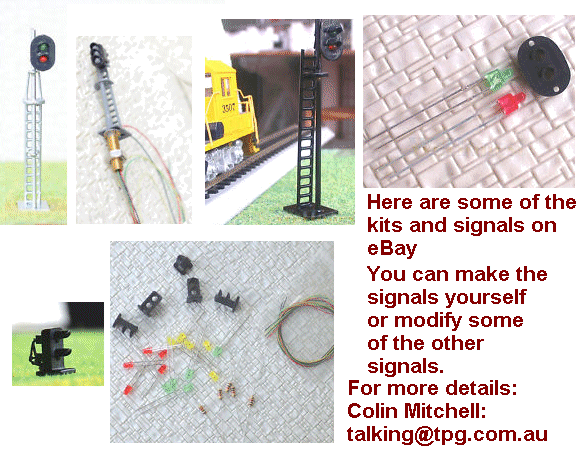
All the kits from the two books are still available and we get lots of
orders, but you must make sure
you are good at soldering and see what the module does, before ordering.
Some of the modules are available fully assembled and tested and some have
been improved or simplified
and you need to contact us before ordering anything.
email
Colin Mitchell:
talking@tpg.com.au
 Electronics
for Model Railways-1 .pdf
(35MB)
free to download
Electronics
for Model Railways-1 .pdf
(35MB)
free to download
Electronics
for Model Railways-1 .doc
(13MB)
free to download
 Electronics
for Model Railways-2 .pdf
(56MB)
free
Electronics
for Model Railways-2 .pdf
(56MB)
free
Electronics
for Model Railways-2 .doc
(13MB)
free
For a
list of every electronic symbol, see:
Circuit Symbols.
For more articles and projects for the hobbyist: see
TALKING
ELECTRONICS WEBSITE
email Colin Mitchell:
talking@tpg.com.au
Talking
Electronics website has more modules and kits
than shown in this index
and the instructions are available
in the two books shown above. As well as
more projects on the website.
New projects and ideas are being added all the time.
|
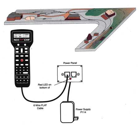
INTRODUCTION If you have
DCC Digital Command Control on your model railway, or are
thinking about using it or starting a layout with this feature, here
is a website dedicated to helping you: Digital
Command Control
is a standard
for a system to operate model railways so that two or more
locomotives can be controlled independently on the same section of
track. |
|
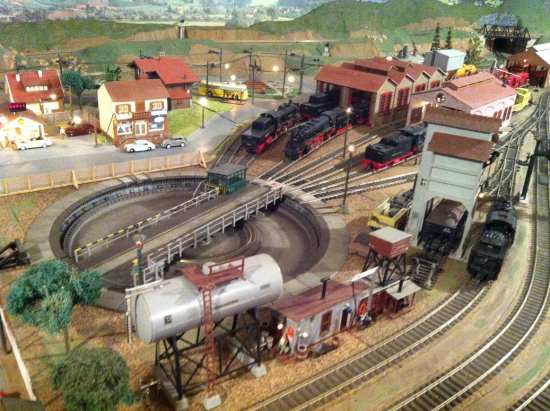
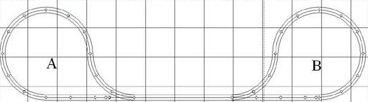
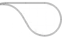
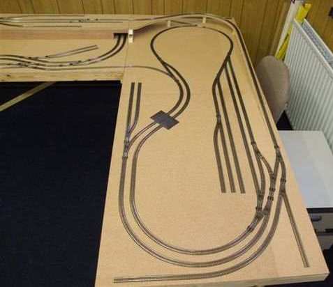
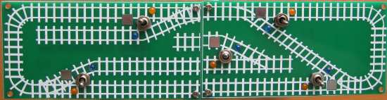
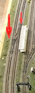
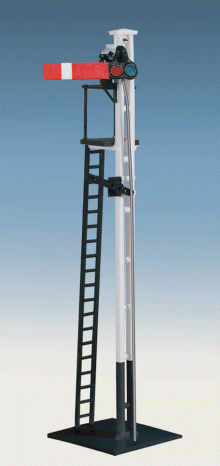
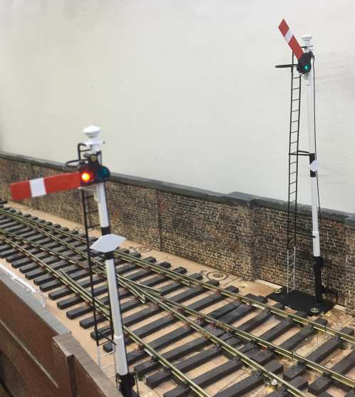
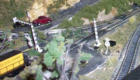
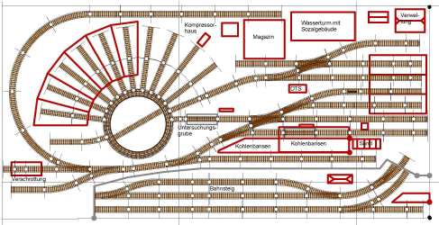
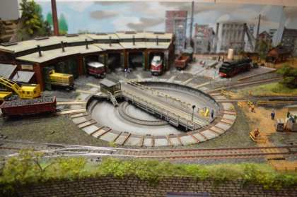
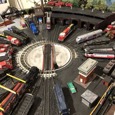
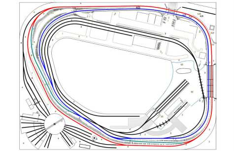
NOTE: Here are 2 of
the latest images: There are 200
more photos of layouts on the website: The next
stage is to add points (turn-outs) or cross-overs: |

 Talking
Electronics has many different modules to operate points remotely
and you will find them all here, in this article, on the page you
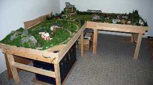
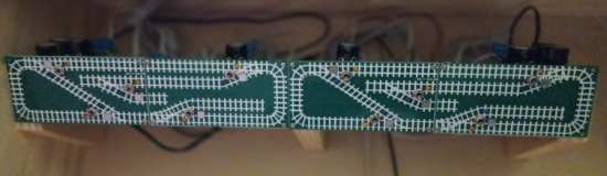
are now viewing. Here are some layouts from readers:
Talking
Electronics has many different modules to operate points remotely
and you will find them all here, in this article, on the page you
are now viewing. Here are some layouts from readers: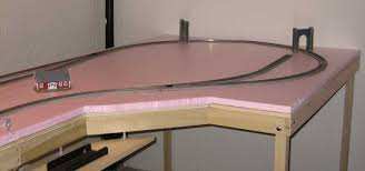
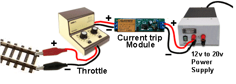
Every project
needs POWER. Power is ENERGY (actually: Power over a period of TIME
is energy) and it comes from a battery or a POWER SUPPLY.
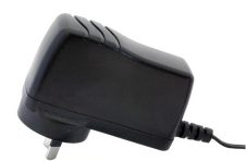
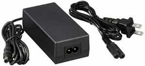
Power
supplies are also called wall warts, plug packs, chargers or
adaptors and must be of the type that is SAFE. In other words, you
must be able to touch the output wires and the tap in the kitchen
and not get killed.
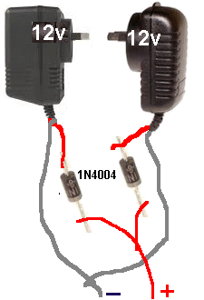
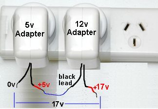
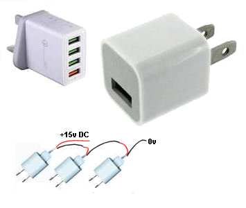
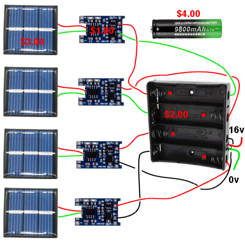
USING DC ADAPTORS IN PARALLEL
Here is a typical 18v power supply for a model railway. This is the ideal supply, but it is expensive and our aim is to show how to produce the same output voltage by using much cheaper items (Plug Packs etc.)
USING AC ADAPTORS IN PARALLEL
USING DC ADAPTORS IN SERIES
You can
connect any TWO or THREE together and the output voltage will be the
sum of all the voltages and the current will be determined by the
lowest current of the 3 adapters. If you do not
have any old Plug Packs, you can buy new ones on eBay for a few
dollars.
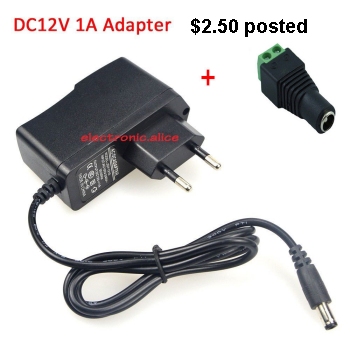
THE BEST ADAPTOR:
The best DC
adapter for all the CDU modules is a 24v or 30v supply made from
two 12v adaptors in series of three 10v adaptors in series.
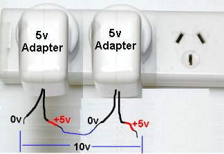
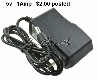
5v,
10v, 15v POWER SUPPLY
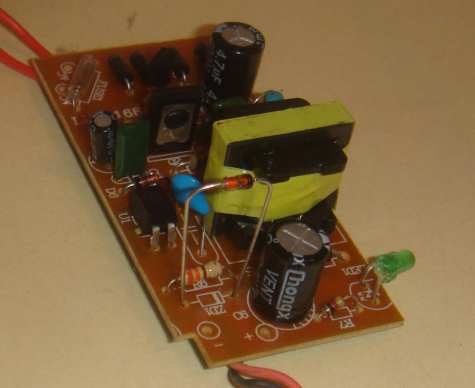
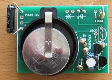
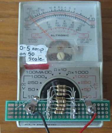
The $2.50 plug Pack above was purchased as 12v @ 1 amp. It was
easily opened-up via a screw and clip, to reveal the PC board shown
below.
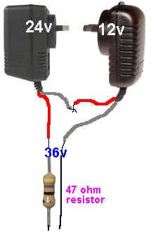
36V
!!
THE
ALTERNATIVE TO A WALL WORT Let's look at what we are talking about:
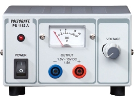
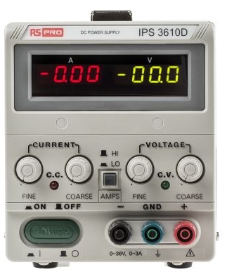
BENCH POWER SUPPLY
They come in all sorts of arrangements and offer current limiting
and output voltages from 0v to 35v (or higher) at 1 amp to 10 Amp
or more.
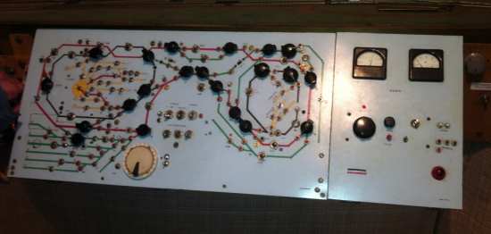
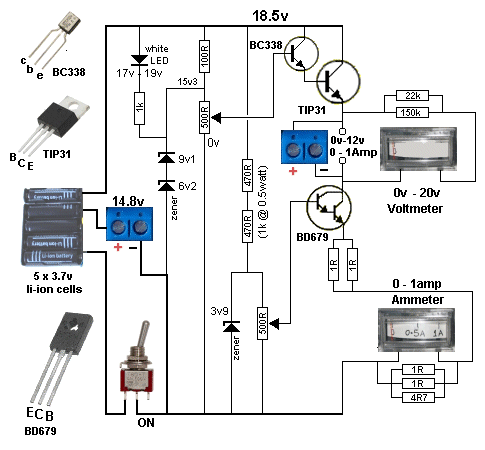
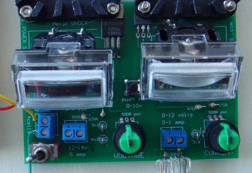
Power Supply MkII
The following project is a 0v to 12v BENCH POWER SUPPLY with
current limiting and has an output of 1 amp. This is sufficient for
all types of testing and you can increase the values by referring to
the circuit.
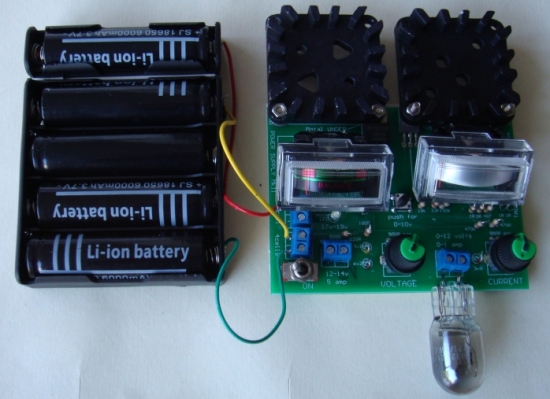
This is the cheapest, safest Power Supply you can get.
Here is a set of 4 Li-ion cells. Just use the 4 lower cells in a 4-cell carrier. The top cell is just to increase the voltage slightly so the project will produce slightly more than 12v at 1 amp.
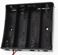
The 4-cell carrier can be bought on eBay for about $2.50
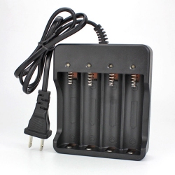
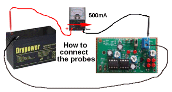
The charger below will charge a single cell at about 500mA to 700mA and connects to your USB port on a laptop. You can only charge one cell at a time with this arrangement.
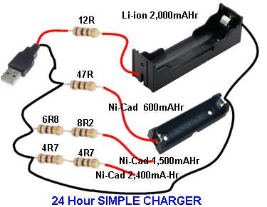
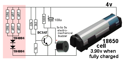
The 1 ohm resistor will discharge the cell quickly. The cell voltage
must not go below a minimum voltage of 2.8v. You need to place a
voltmeter across the resistor while discharging to make sure you do
not discharge the cell below its recommended minimum. The module in
the photo charges the cell quite quickly and at 4.2v the cell is
charged to 90% (or more) and the circuit turns OFF. More details of the project shown above can be found HERE. It describes a 1 amp adjustable POWER SUPPLY that can be used to power your locos or as a BENCH POWER SUPPLY for all your testing.
CURRENT
CONCLUSION ooooooooooooooooooooo0000000000000000000000000oooooooooooooooo
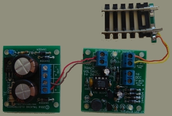
BOOST CONVERTER |

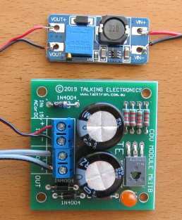 The
input wires (on the right) will accept a DC voltage from 5v to 20v
DC (from a plug pack or wall wort) and produce an output voltage
that has been adjusted by the 10-turn pot. We set the output voltage
to 26.5v so the electrolytics on the CDU module see a voltage of 25v
(after the input diodes).
The
input wires (on the right) will accept a DC voltage from 5v to 20v
DC (from a plug pack or wall wort) and produce an output voltage
that has been adjusted by the 10-turn pot. We set the output voltage
to 26.5v so the electrolytics on the CDU module see a voltage of 25v
(after the input diodes).
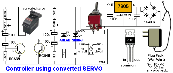
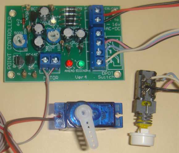
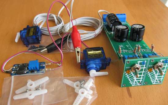
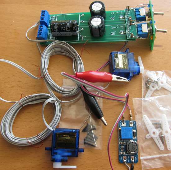
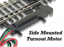
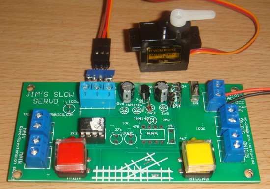
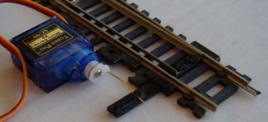
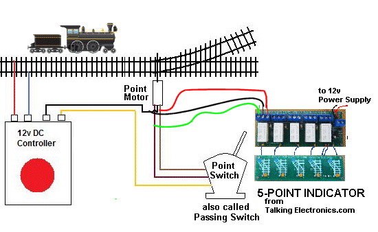
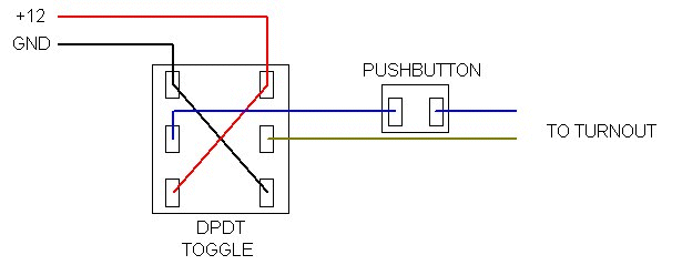
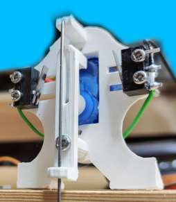
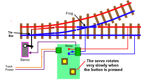
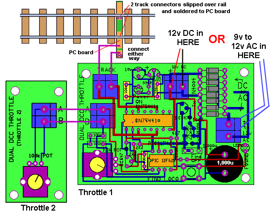
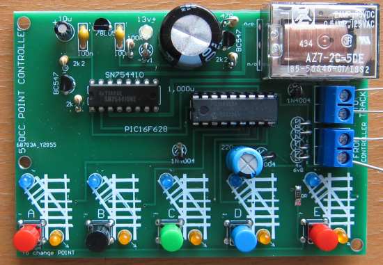
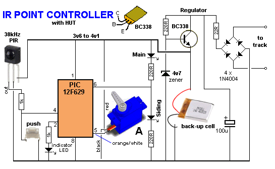
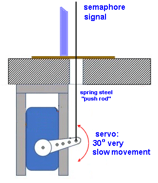
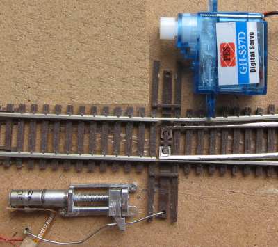
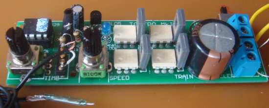
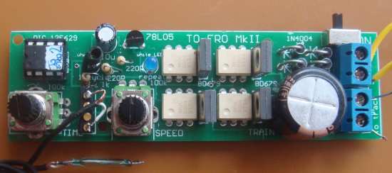
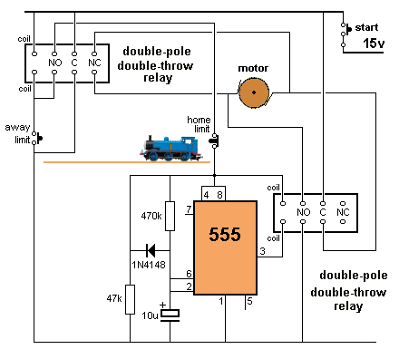
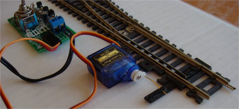
This is PART "A" of our discussion on controlling a point. Talking
electronics has designed and produced a wide range of controllers to
turn a manual point into remote operation. We use a servo to change
the point and not a solenoid. This means nothing will burn out and
the cost will be lower. The servo is also called a motor and gearbox
and the different types will activate the point either slowly or
quickly. You can mount the mechanism either on top of your layout or
underneath.
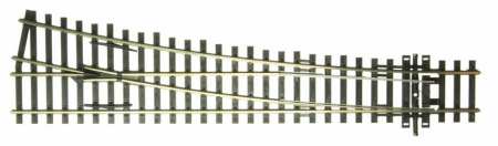
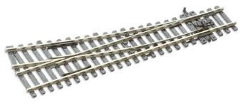
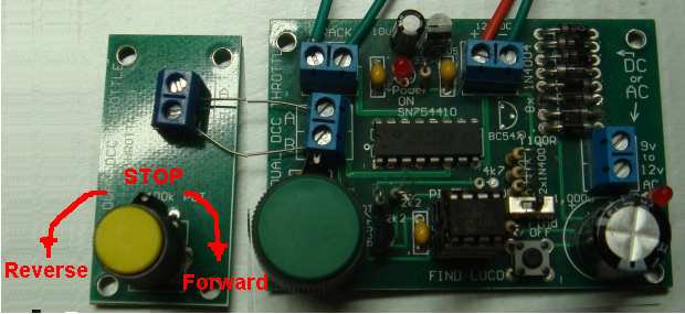
A
Point Controller is a "device" or "MOTOR" or "SOLENOID" that changes
the point from "ahead" to "Siding."
All layouts need a point
or lots of
points so you can make an impressive layout and have the trains
leave and enter the main line and provide shunting yards and loops
and interconnecting lines.
If you have a
solenoid operated point, we will cover it later:
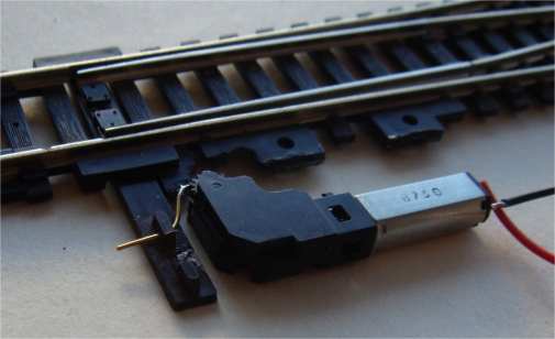
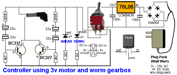
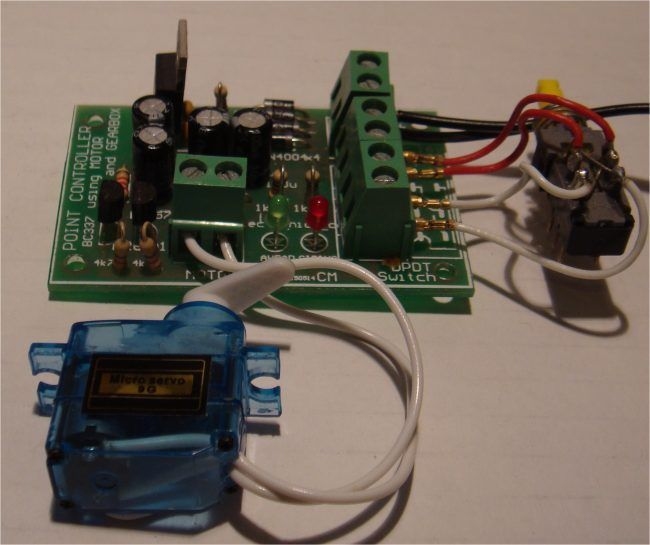
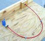
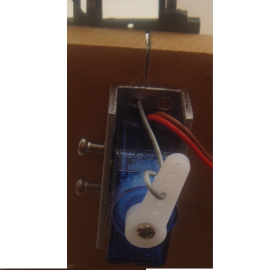
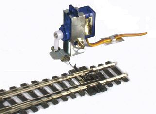
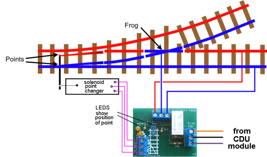
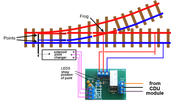
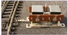
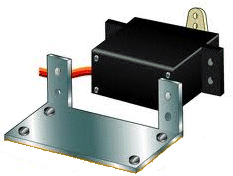
We connect a motor and worm gearbox as shown in the following image to the actuating lever on the point:
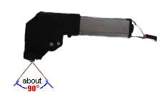
Image shows the control rod on the gearbox is
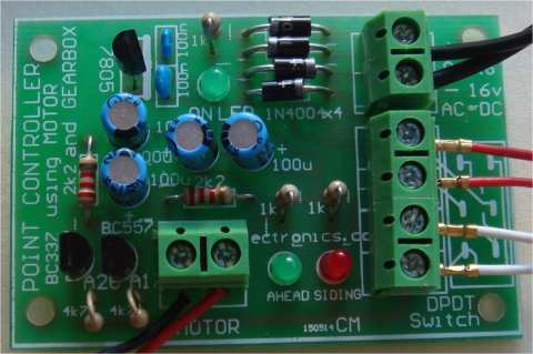
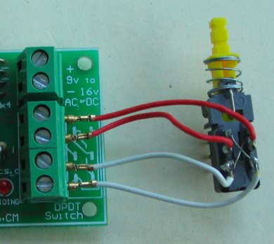
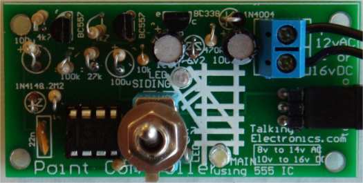
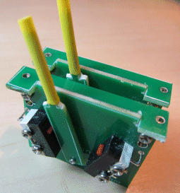
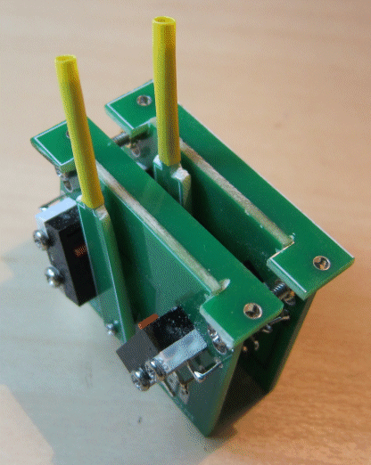
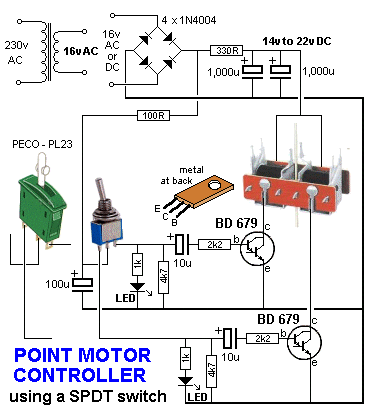
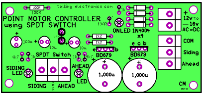
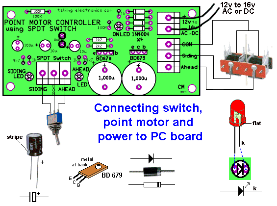
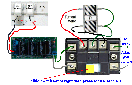
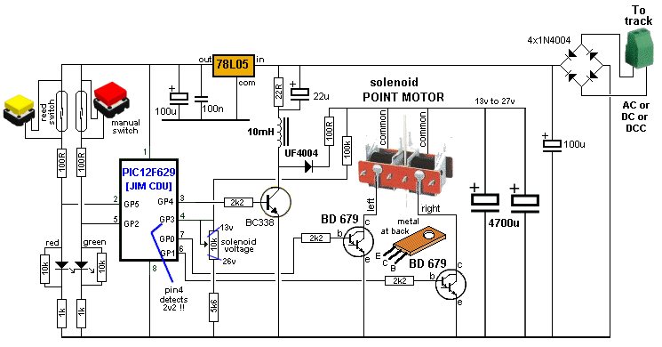
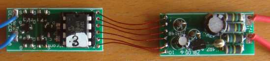
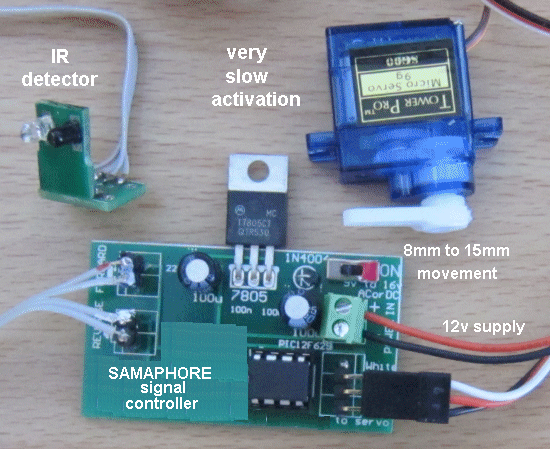
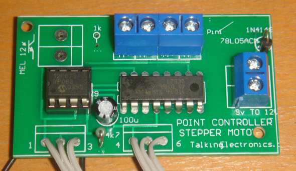
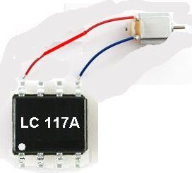
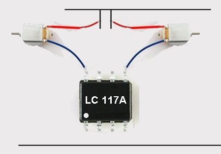
The following image is the module that controls and limits the motor's operation. It allows the motor to be connected to a 9v to 16v AC or DC supply.
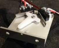
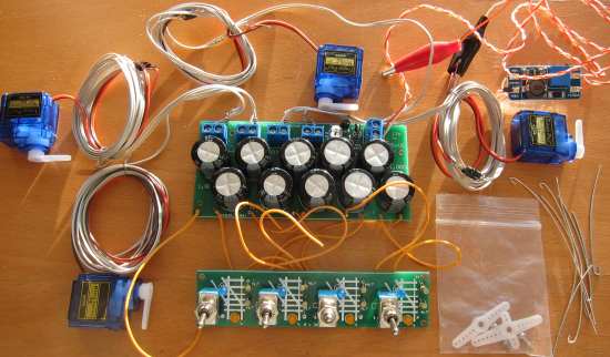
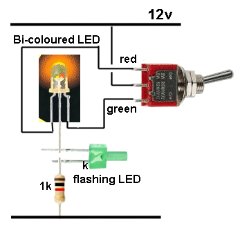
You get a
micro motor with worm gearbox and module and DPDT push-push switch
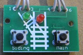
and the position of the point is shown on the red and green LEDs on
the module. The movement of the point is fairly rapid. There are
other modules with slow movement.
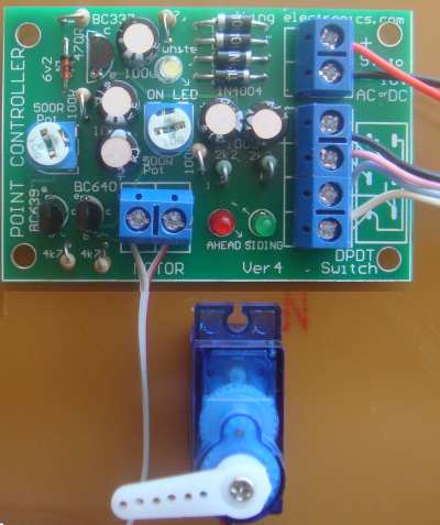
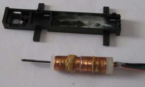
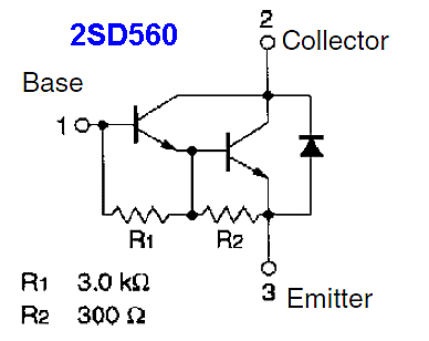
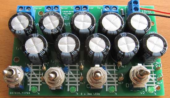
The circuit above uses a 3v micro motor with worm gearbox. The latest PC board has a number of improvements with two 500R pots to adjust the strength of the throw of the arm. oooooooooooooo0000000000000000000000000000ooooooooooooooooo
CHOICE NUMBER 2:
oooooooooooooo0000000000000000000000000000ooooooooooooooooo
CHOICE NUMBER 3: The Printed Circuit Board has 2 x 500R mini trim pots to adjust the amount of travel of the output arm.
oooooooooooooo0000000000000000000000000000ooooooooooooooooo
oooooooooooooo0000000000000000000000000000ooooooooooooooooo
CHOICE NUMBER 5:
Click
Here
to order. oooooooooooooo0000000000000000000000000000oooooooooooooooo
CHOICE NUMBER 6: oooooooooooooo0000000000000000000000000000oooooooooooooooo
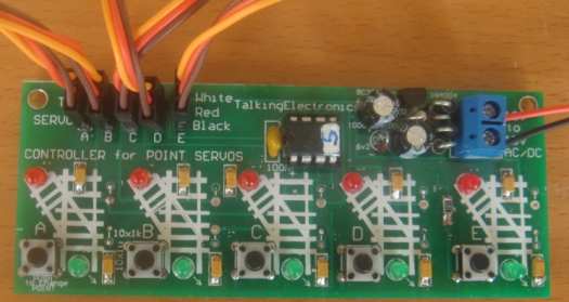
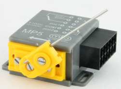
CHOICE NUMBER 7: The on-board tactile buttons need to be pressed for about 1/2 second for the program to recognise the button and activate the servo to set the point to the correct position. You need to set each point so that the PC board reflects the correct position of the point. Do this will all 5 points and you are ready to drive the loco. oooooooooooooo0000000000000000000000000000oooooooooooooooo
CHOICE NUMBER 8:
oooooooooooooo0000000000000000000000000000oooooooooooooooo
CHOICE NUMBER 9: A description of how the circuits works is HERE
CHOICE NUMBER 10:
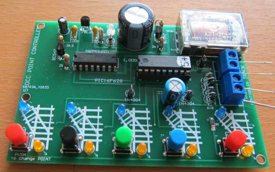
The angular movement of the motor/gearbox is controlled by the
resistors under the PCB and the voltage of the pre-voltage module.
The position of the point is shown by 2 LEDs on the module with an
outline showing the track with siding. This makes it easy to see the
position of the point.
SUMMARY |
|
POINT MOTORS oooooooooooooo000000000000000oooooooooooo
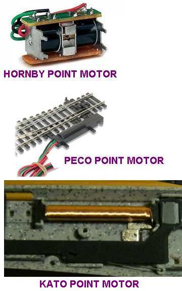
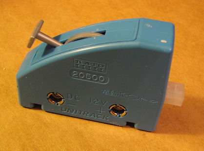
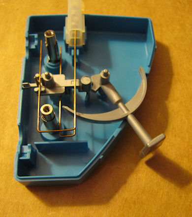
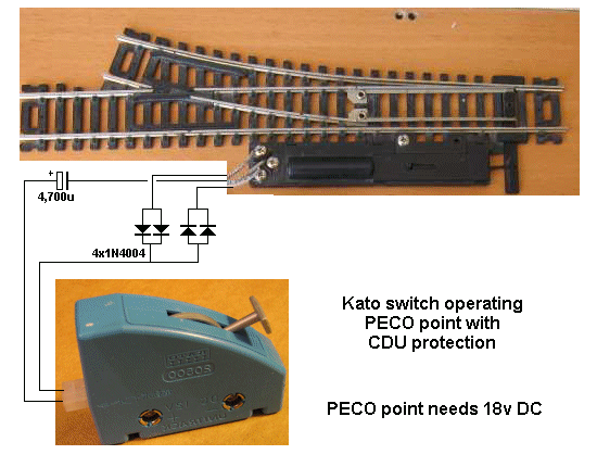
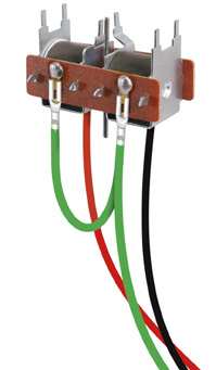
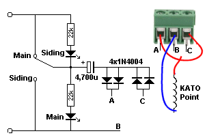
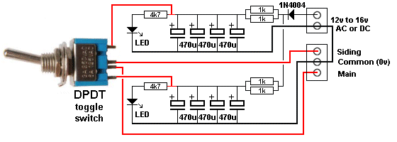
KATO SWITCH OPERATES PECO POINT
The switch is simply a double-pole double-throw PASSING SWITCH that
supplies energy to the point at the mid-way of the travel of the
lever. |
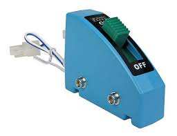
Point Motors are also called
Point Controllers or Switch Machines and you
need to be very careful as some of them need control electronics
(which is not included in the price)
while others are just an empty box. Blue Point
Switch Machine
$14.00 usd
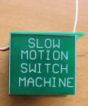
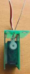
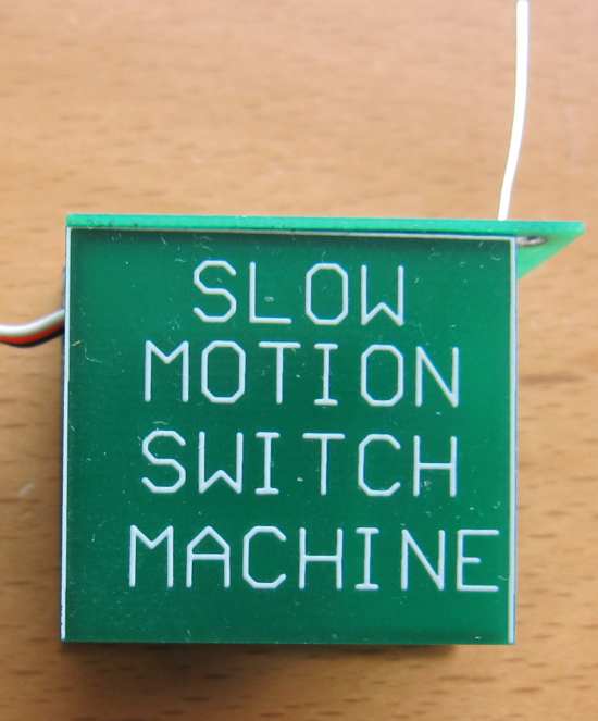
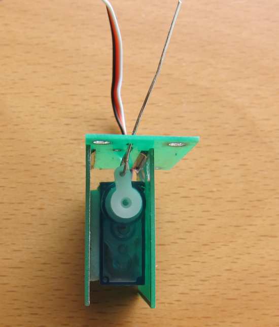
Turtle Slow Motion Switch Machine $10.00 usd
The Turtle Slow Motion Switch Machine is
fitted under your layout and requires an electronics module
to provide slow activation for the servo. The module
will activate 5 Slow Motion Switch Machines and costs $25.00 usd plus
$10.00 for five 2metre extension leads.
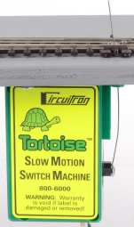
Tortoise Slow Motion Switch Machine $35.00 usd
Motor stalls at each end of throw
Turtle Fast Switch Machine
COBALT
Analogue $35.00usd You can choose the Slow
Motion or Fast Action Turtle Switch Machines from Talking
Electronics for less than 50% of the cost of the devices
on the left.
Slow
Motion and Fast Action Turtle Switch Machines do
not have switches or relays or extra contacts and are simple
to connect to your Control Panel with 2 or 3-core
lead.
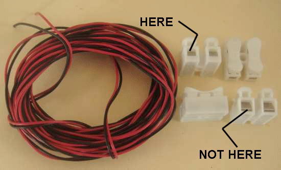
A 2-core extension lead (2metres long)
costs $2.00 extra. |
|||||||||||||||||||||||||||||
 This
Switch Machine is fast in operation and very small. It
requires an electronics module for operation (and timing) and
has point indication to show the position of the point. The
timing module TURTLE FAST controls 5 points
This
Switch Machine is fast in operation and very small. It
requires an electronics module for operation (and timing) and
has point indication to show the position of the point. The
timing module TURTLE FAST controls 5 points 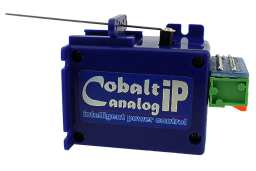


 Another
Point Controller that is hard to find.
Another
Point Controller that is hard to find. 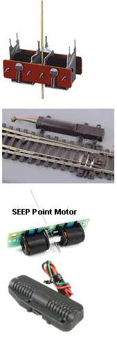

This is PART "B" of our discussion on controlling a point.
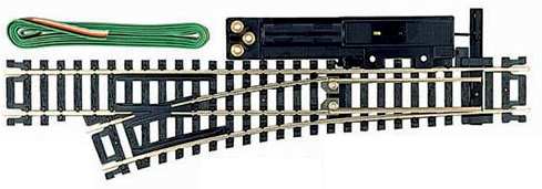
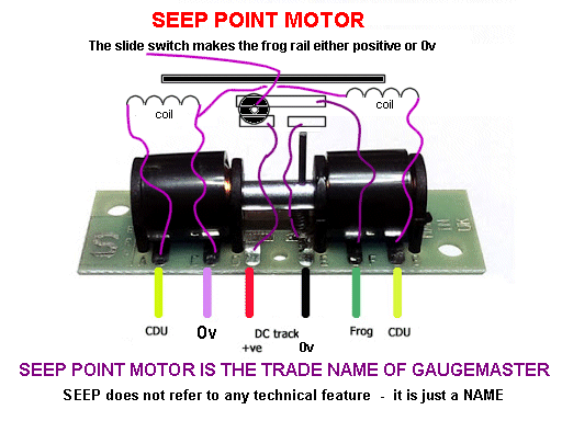
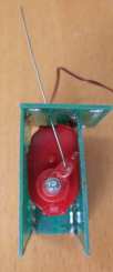
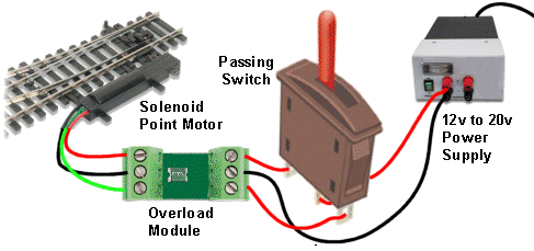
The SOLENOID Point Motor consists of two coils of wire that
alternately pull a metal rod into the middle of the solenoid and at
the same time change the position of the point.
oooooooooooooo0000000000000000000000000000oooooooooooooooo
CHOICE NUMBER 8:
-
see the new version (dual) for $18.00
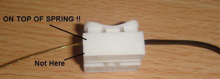
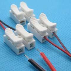
The screw terminals make it easy to fit to your layout.
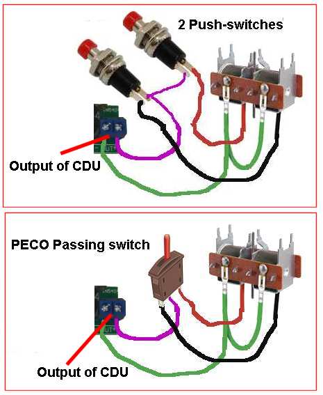
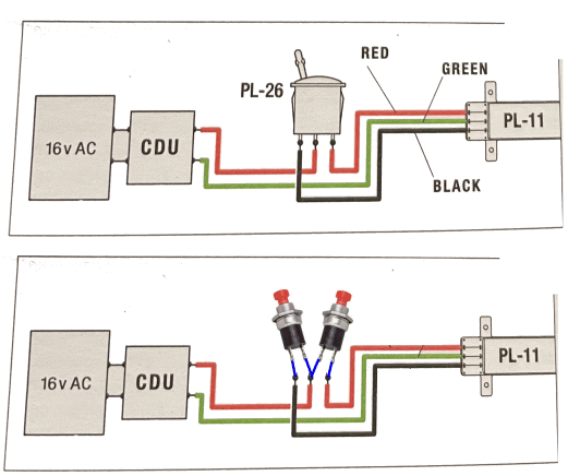
The green
wire is called the COMMON
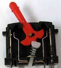
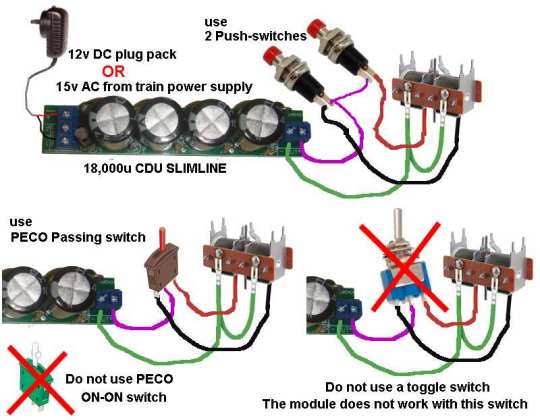
The PL-26 switch is called a PECO PASSING SWITCH because it
only makes contact when the lever is just before or just after the
top position. This means it is not making contact when fully left or
fully right.
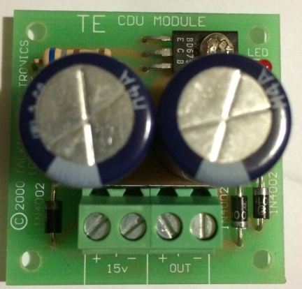
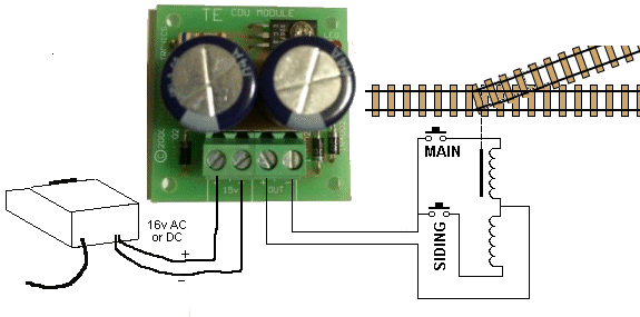
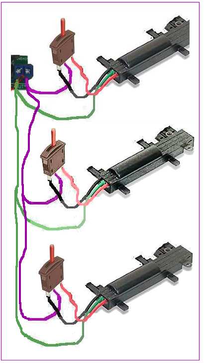
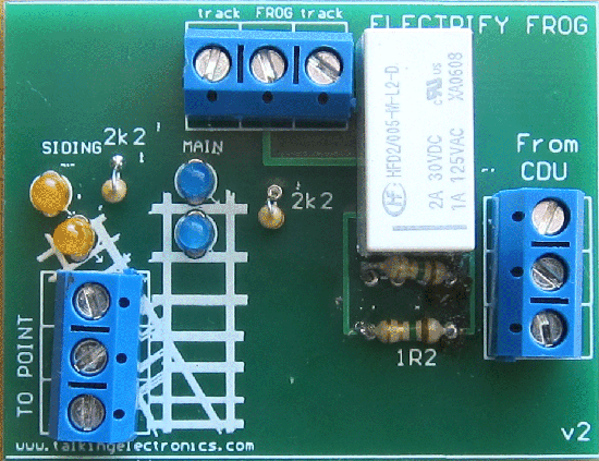
Our CDU module fits between the Power Supply and the switch or
switches to a SOLENOID POINT MOTOR. It is designed to deliver
a short pulse of energy to the solenoid to change the position of
the point. A Passing Switch will deliver a pulse of energy
but if it gets stuck in the mid-position, our CDU will prevent the
point motor "burning out."
PASSING SWITCH -
for Point Motors
The PECO Passing Switch (shown above) is a very bad
design as it does not deliver the energy to the point CORRECTLY when
the lever is moved from one side to the other.
There are two more
switches that can be used to control a solenoid point.
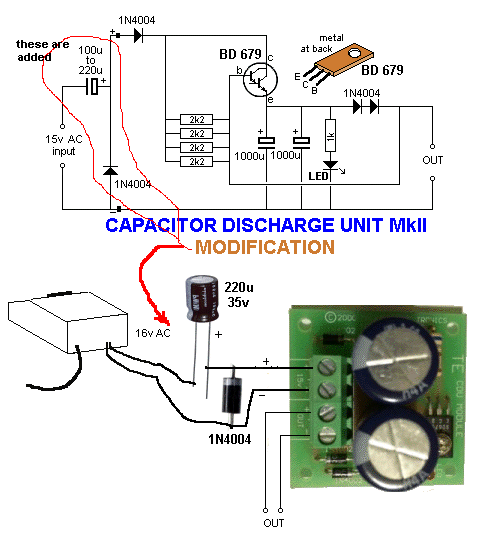
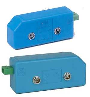
CAPACITOR DISCHARGE UNIT MkII - MODIFICATION
Universal EU US Plug Switching Adapter AC 220V-240V To 5 V 12 V 24V
Volt Power Supply DC 5V 12V 24V 1A 2A 3A 5A Power Adapter
Output Voltage 24v US Plug Current 1A $3.60
CDU MKIIB shown above is no longer available. It has been upgraded.
The new CDU MKIIB module comes with a pre-voltage module and push
switches with front panel.
This Capacitor Discharge Unit is easy to connect to your layout with
screw terminals. ooooooooooooo0000000000000000000000000000oooooooooooooooop>
CHOICE NUMBER 8A:
oooooooooooooo0000000000000000000000000000oooooooooooooooo
CHOICE NUMBER 8B: FOR 2-KATO POINTS
To operate a KATO
point connect the two outer screw terminals together
CHOICE NUMBER 9:
The amount of energy delivered to the solenoid depends on the
voltage delivered to the module. For 12v DC supply, the solenoid
will work very delicately and will be suitable for small solenoids
used in "Z-scale." Supplying 16v AC will deliver FOUR times more
energy and will be suitable for larger scales and can operate 2
points. oooooooooooooo0000000000000000000000000000oooooooooooooooo CHOICE NUMBER 10:
Talking Electronics has an In-line version that takes up less
space on your console. This In-line CDU module has two LEDs
that show the position of the point. It is fitted to your control
panel and the LEDs show the position of a point. This very handy for
a point that cannot be seen from the control area.
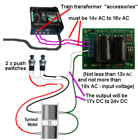
The input voltage needs to be 12v to 16v AC or DC and you may need two adaptors in series to get this voltage. See Chapter 1 for the Plug Packs (or Choice Number 11). oooooooooooooo0000000000000000000000000000oooooooooooooooo
CHOICE NUMBER 11:
You can use the "accessories" output of a train transformer if it is
DC (14v DC to 24v DC) or if the accessories output is AC (14v AC to
18v AC). The module has been tested up to 20v AC but it is best to
keep to 18v AC max.
This principle applies to all CDU's. It does limit the "inrush current" and you can email me if you are adding a VOLTAGE DIVIDER to another project to see if any reduction in operation will occur. oooooooooooooo0000000000000000000000000000oooooooooooooooo
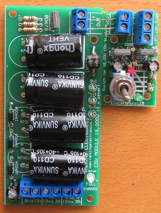
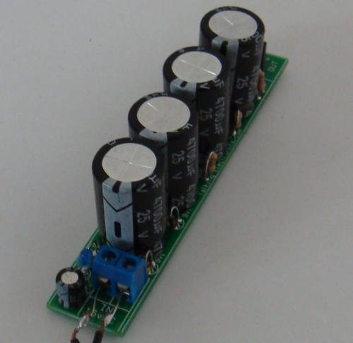
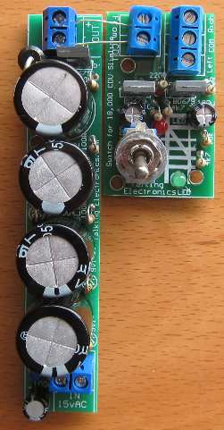
A
larger CDU is also available from Talking Electronics, to change up
to 8 points at the same time:
This Capacitor Discharge Unit is easy to connect to your layout
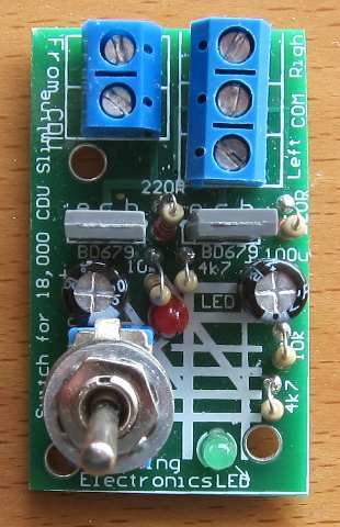
with screw terminals. A Switch Module can be fitted to this CDU to activate the solenoid point and also show the position of the point via two LEDs:
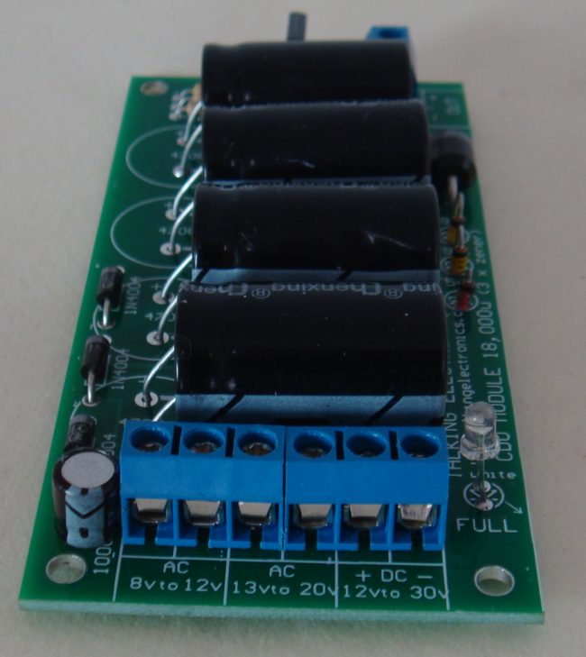
The SWITCH MODULE (shown in the images above) connects to 18,000u
CDU for $7.00 extra. oooooooooooooo0000000000000000000000000000ooooooooooooooooo
CHOICE NUMBER 13:
oooooooooooooo0000000000000000000000000000oooooooooooooooo
CHOICE NUMBER 14:
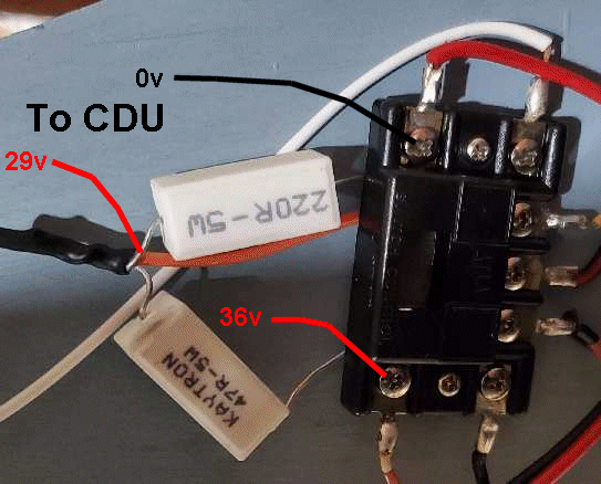
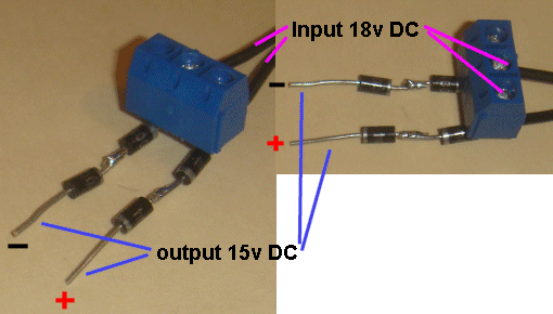
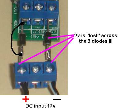
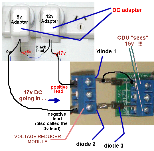
The VOLTAGE REDUCER MODULE consists of a 3-terminal block and
4 power diodes and screws into the 3-terminal block on the module.
If the input voltage is 17v, you can remove one of the diodes by soldering a link across one of the diodes (to short it out), as shown in the following image:
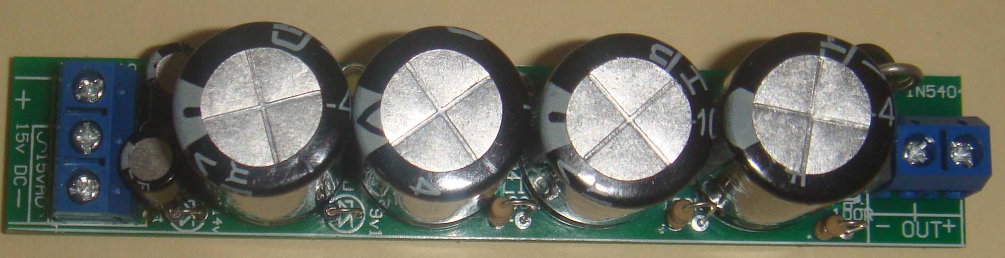
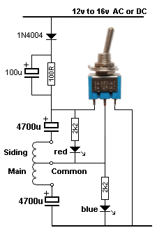
If the input voltage is 16v you can remove 2 diodes and if it is 15v, you do not need the VOLTAGE REDUCER MODULE. If you want to deliver 15.5v DC to CDU 18,000u Slimline - MkII with two plug packs, here is the circuit:
A Switch Module can be fitted to this CDU to activate the solenoid point and also show the position of the point via two LEDs:
The SWITCH MODULE (shown in the images above) connects to 18,000u
SLIMLINE CDU for $7.00 extra. oooooooooooooo0000000000000000000000000000oooooooooooooooo
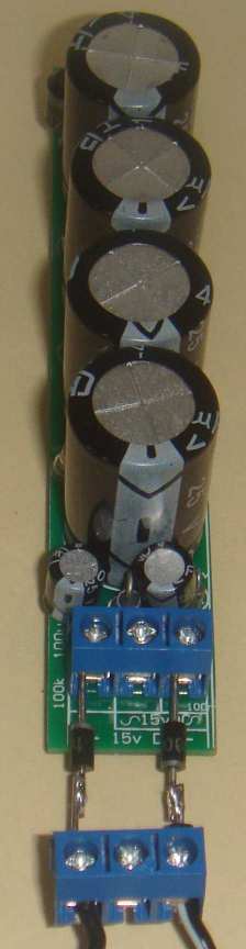
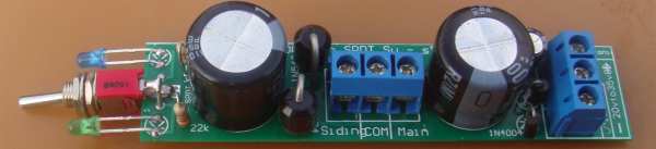
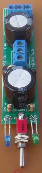
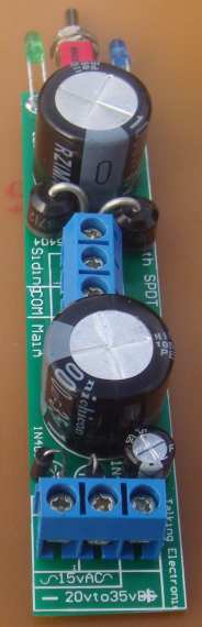
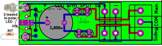
PRE-VOLTAGE MODULE $5.50
The name: Capacitor Discharge Unit with SPDT Switch - SLIM
has been chosen to identify it from all the other CDU modules made
by Talking Electronics.
All the components fit on the PC board and the module comes with 2 x 1,000u electrolytics. The input can be 12vAC to 15vAC or 20vDC to 35vDC.
You can make a 12v 24v or 36v supply very cheaply by using 24v and
12v plug packs. These are available on eBay for less than $10.00
(combined) including postage.
Using an old Printer Power Supply
There are lots of other power supplies from discarded electronic equipment and you just have check everything before you throw it out.
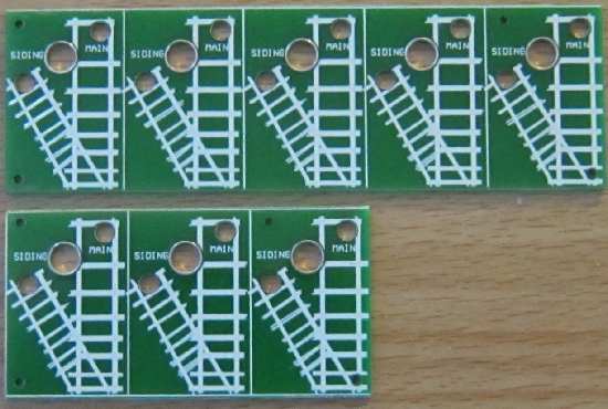
2
MODULES
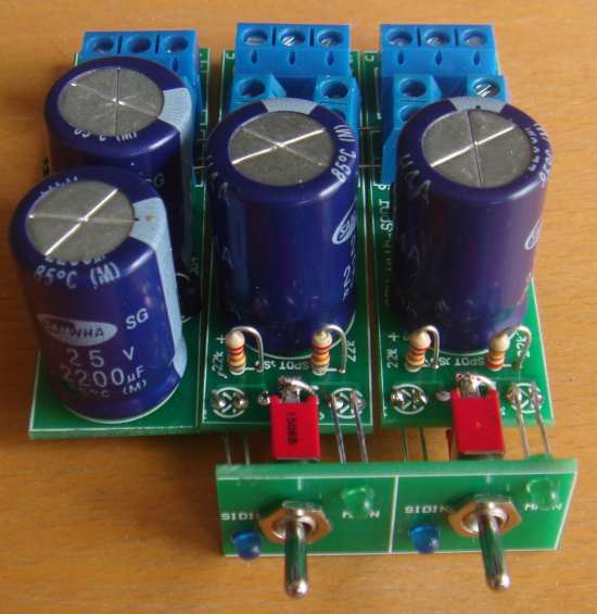
ooooooooooooooooooo000000000000000000000ooooooooooooo 5 MODULES
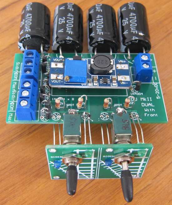
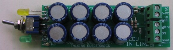
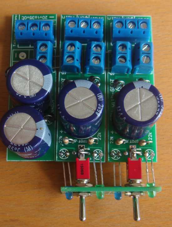
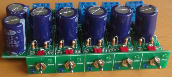
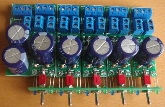
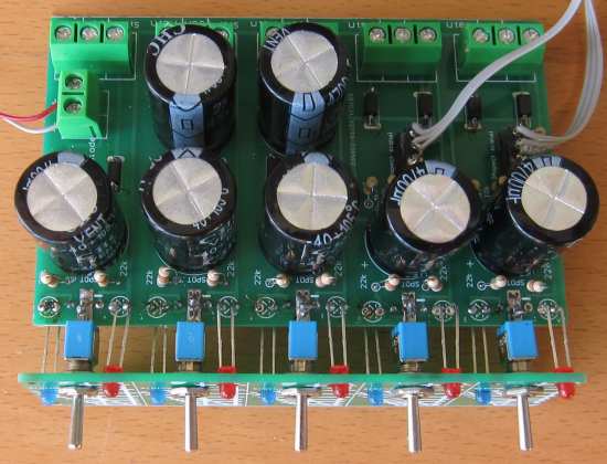
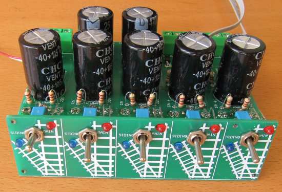
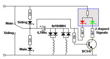
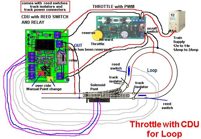
CDU with output for 2-Aspect signals:
This module comes with a pre-voltage module to make things easy for
you. You just need a supply of 9v to 20v DC and the pre-voltage
module will output 25.5v to the CDU modules.
You can mount 2 or 5 modules "side-by-side" and use the face-plate
shown in the photo below to connect them together and fit them to
your console.
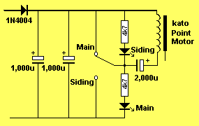
The circuit for the 5-Modules version has 2 x 4,700u electrolytics
in the power supply section because the charging of the 2,200u (in
the second part of the circuit shown above), when the switch is in
the "MAIN" position, will take a lot of energy from the 4,700u in
the power supply and the voltage across it will dip 50%
(theoretically). When 5 modules are connected to the power supply,
this will be passed to the other modules and affect the operation of
the other points at a time when they should not be affected.
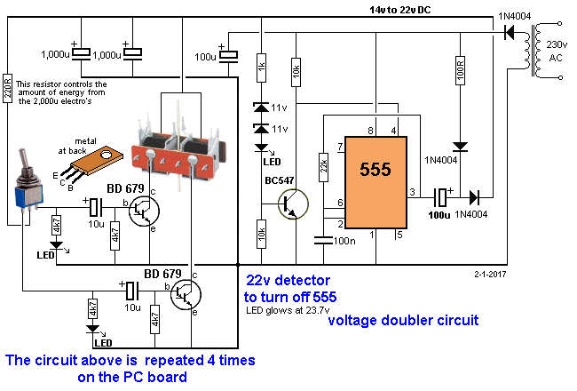
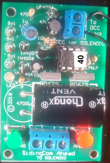
This CDU (Capacitor Discharge Unit) module has been designed with
voltage-doubling components so you can use the 12v DC or 15v AC
terminals of your train power supply. It also has voltage regulating
to prevent over-charging the electrolytic and an indicator LED to
show when the electrolytic is fully charged.
This CDU has improvements and now replaces some of the older designs as it operates better at low voltage and provides equal thrust in both directions.
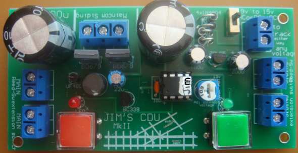
This project combines a number of features from three of the
projects we have previously designed for Model Railway Hobbyists.
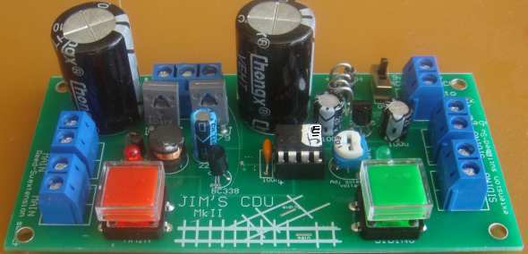
It is available as a kit or fully built and tested.
THE
CIRCUIT |


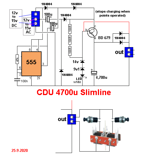
JIM's CDU MkII circuit
|
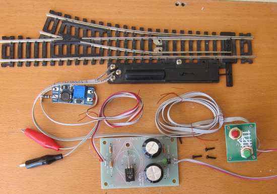
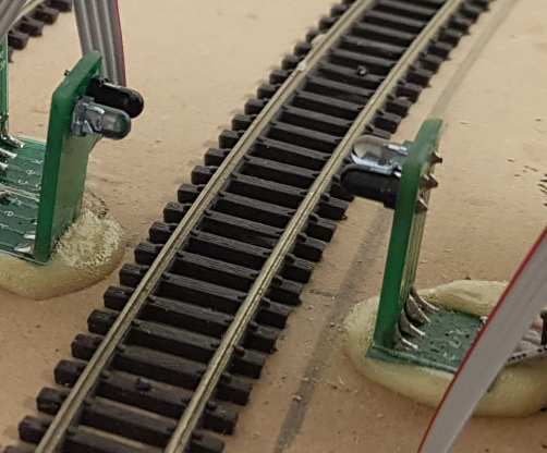
SOLDERING THE KIT
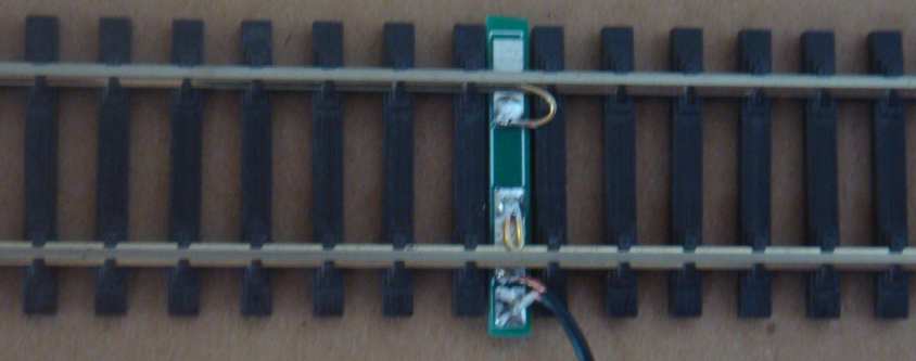
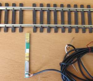
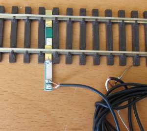
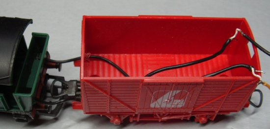
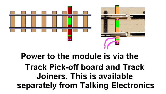
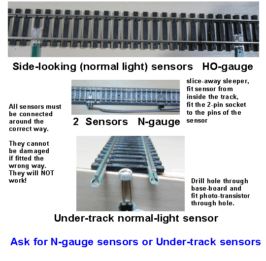
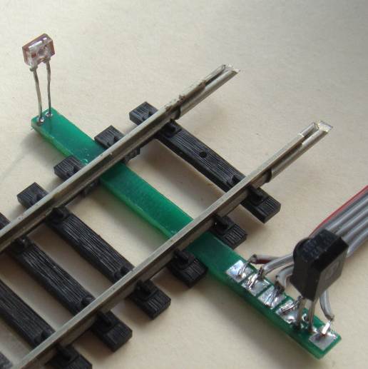
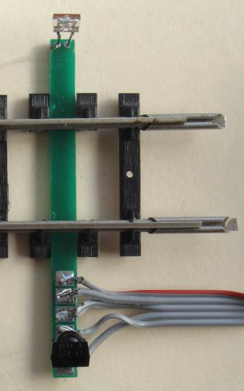
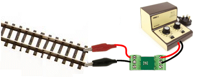
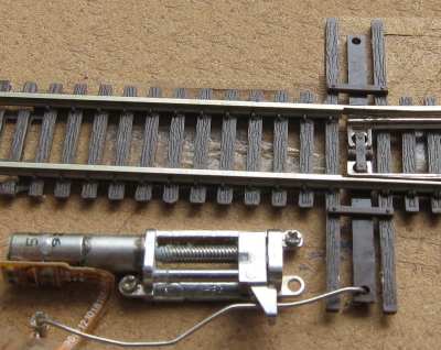
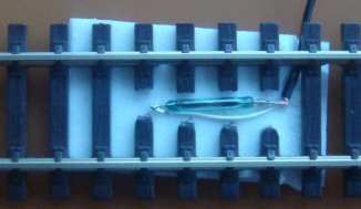
Alternatively, you can ask for Track Pick-off "using Rail Joiners." You will need to get to the track, remove the rail joiners that presently connect the rails, and fit the track jointers as shown in the following image:
CONCLUSION oooooooooooo000000000000000000oooooooooooooo
CHOICE NUMBER 18:
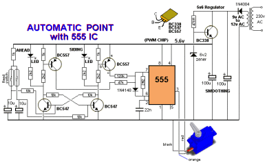
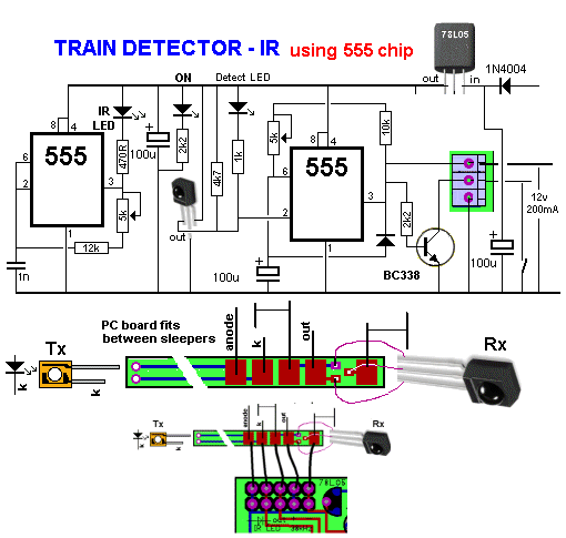
The original circuit used two 555 IC's. The new and improved circuit
uses a microcontroller and 15 fewer components !! That's why some
of the components are no longer required.
CHOICE NUMBER 19:
The SLOW MOTION SWITCH MACHINE costs $8.50 usd and comes with 2
metre of 3-core lead.
This is the latest Slow Motion Switch Machine using digital control
to the motor.
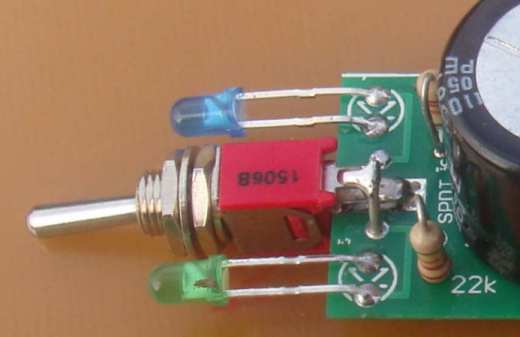
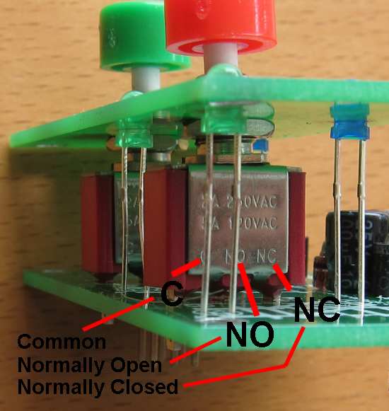
The switch MUST be fitted so the letters "C" "NO" and "NC" can be
seen as per the image above. They will not work if fitted the wrong
way around. These are special switches - push switches - and not
toggle switches. Push the legs through the holes of the printed
circuit board and before you solder the pins, try the operation of
the module. When you know it operates correctly, solder the pins
with the fine solder provided. |
|
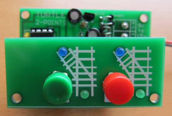
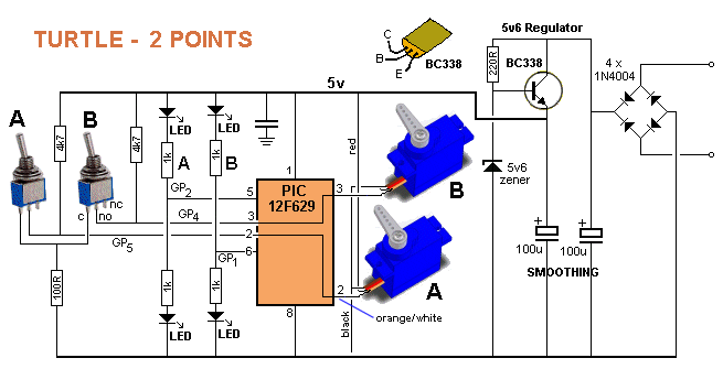
TURTLE - 2 POINTS CIRCUIT All the work
is done by the microcontroller. |
|
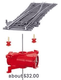
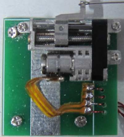
PECO PL1000 TWIST LOCK POINT MOTOR The PECO Twist
Lock Point Motor is a double-acting solenoid and is not really a
"motor" in the sense of the word. A motor has a revolving
output shaft and does not "click" or "vibrate" or "pulse."
The PL1000 is placed
under the layout and it has a resistance of about 3 to 6 ohms, so
the current it will take from a 12v supply will be 2 to 3 amps. It
must be activated for a very short period of time, otherwise it will
get hot and melt the plastic. |
|
CHOICE NUMBER 20: Point Controller for 1 Motor/Gearbox $18.00 see also for 2 Motor/gearboxes and 4-Motor/gearboxes 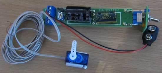  Convert your manual point into a remote point with this motor/gearbox activator using the push-rod supplied. The module has a front panel showing the position of the point and operates from a 12v supply. The on-board mini trim pot adjusts the "throw" of the push rod to suit mounting on your layout or under the layout. A bracket for mounting the gearbox under your layout is also available. This is the cheapest way to convert points to remote operation. Buy Point Controller using Motor/Gearbox $18.00 plus $8.50 post |
|
CHOICE NUMBER 21:
Buy 5 Point Controller for Servos $25.00usd plus $6.50usd post |
|
CHOICE NUMBER 22:
|
|
|||||||||||
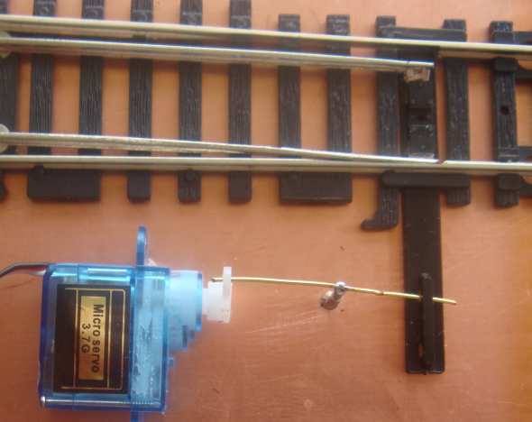
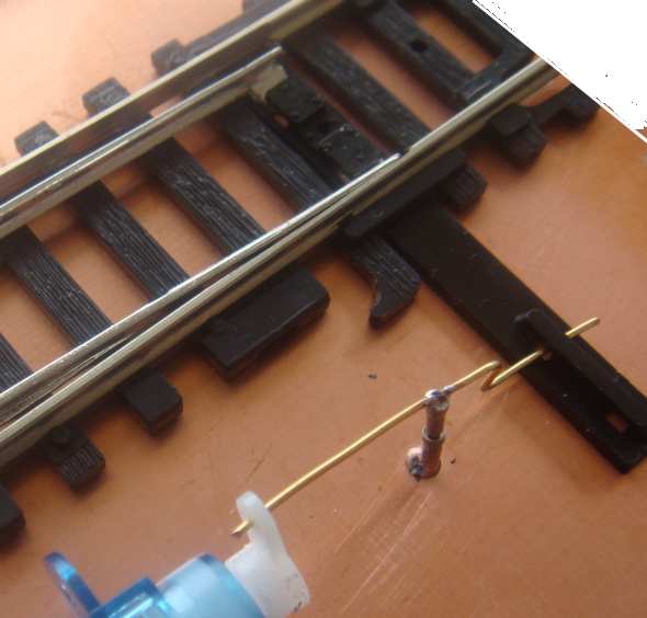
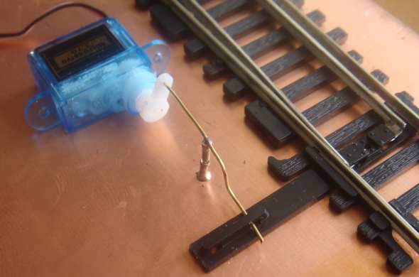
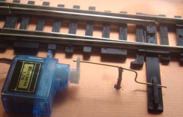
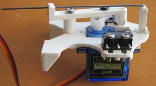
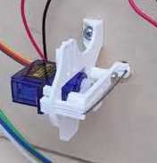
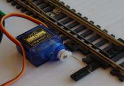
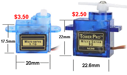
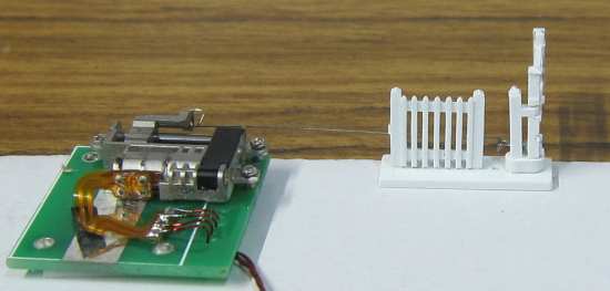
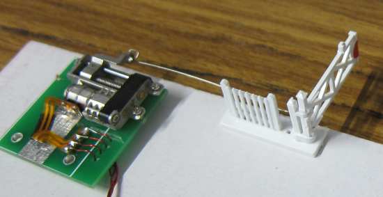
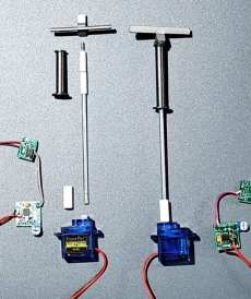
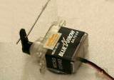
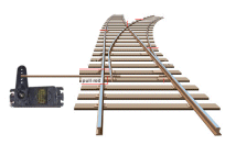
 The image on the left is just an example to show the connection of the servo to the point. The servo can lay down to take up less room.
There are
many ways to connect the servo to the "switching lever" and here's
one way that adjusts the movement of the arm on the servo to the
travel needed by the switching lever. The following images clearly show how the 3.7g SERVO is connected to the point via a LINKAGE:
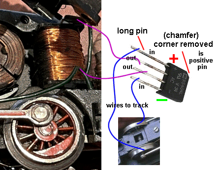
THE
SUPPLY
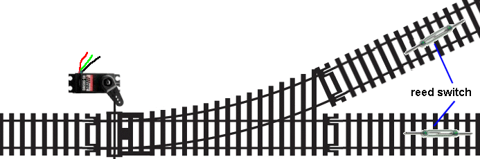
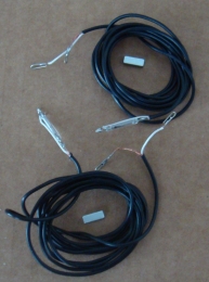
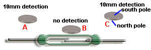
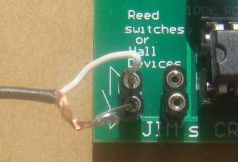
SETTING-UP THE MAGNETS
FITTING the REED SWITCHES
----------------------oooooo000000oooooo--------------------------
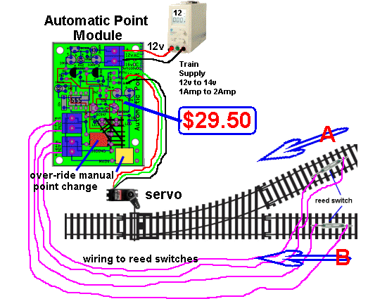
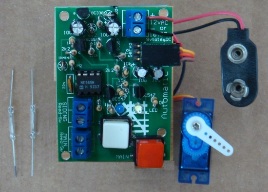
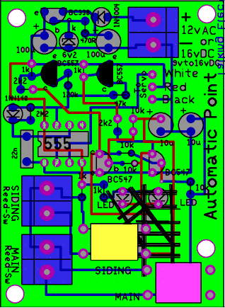
Automatic Point Switcher
is available from: This is
another Automatic Point Controller from Talking Electronics
to cover slightly different requirements.
oooooooooooo00000000000000oooooooooooo
This module changes the point automatically and has 3 other
features so you can design a layout with a loop.
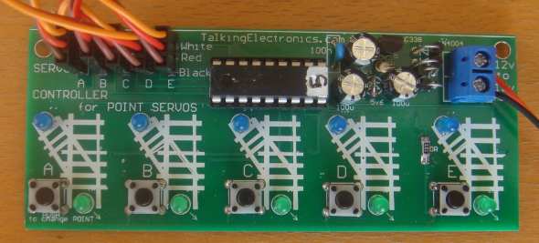
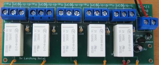
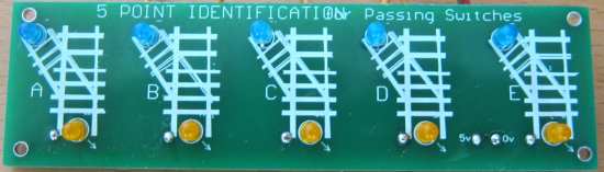
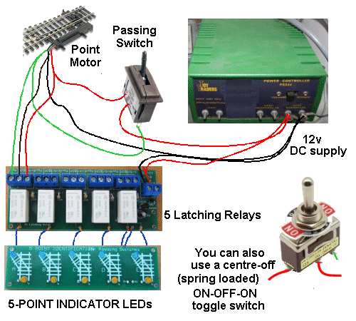
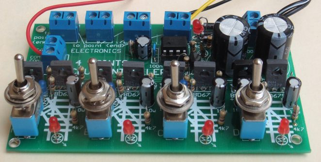
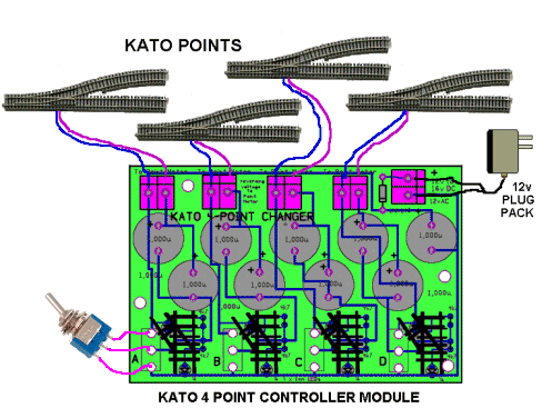
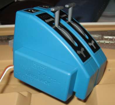
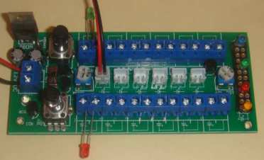
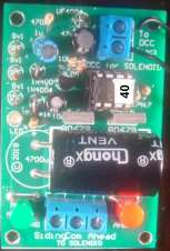
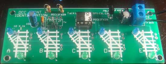
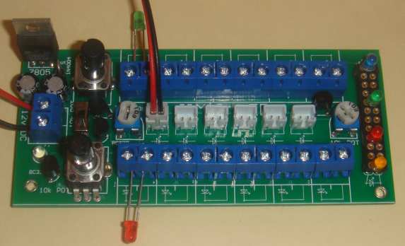
4 Points CDU Controller
This module will change the position of 4 point
motors via the 4 toggle switches and the LEDs on the
board show the position of the point. The module
comes with the switches separate in a plastic bag
because they are too tall to post in out small
posting box. You can solder the switches to the
board or fir them to your control panel and use
3-core ribbon cable. The two outer wires of each
point are connected to the 2-terminals above and the
4 middle wires of the points connect to the
2-terminal block on the left of the module.
The circuit has been included so you know how it connects to the solenoid points. The oscillator circuit using the 555 increases the input voltage to 25v. It is fully built and tested for $35.00 usd plus $8.50 usd postage Please log into your paypal account and send a payment to talking@tpg.com.au for $43.50 usd oooooooooooo000000000000000000oooooooooooooo
CHOICE NUMBER 26:
This module controls 4 Kato points.
The
CIRCUIT
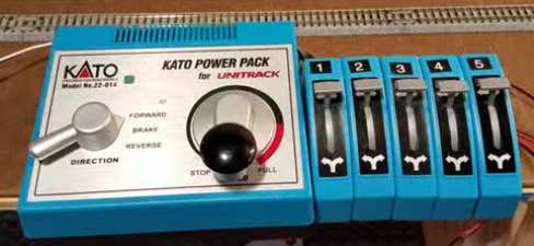
Understanding KATO The KATO Throttle is called KATO POWER PACK
A Kato 22-018 Power Pack is available on eBay for $40.00 shipped and you will need an AC plug pack The KATO 12v AC plug pack costs $25.00 to $40.00 on eBay BUT is for 100v AC and is not much use in the rest of the world. The advertisers don't tell you it's for 100v AC. There is NO 240v version.
What you need is a transformer as shown above. It converts 240v AC
to 12v (or 15v) at about 1 amp. Now we come to adding a KATO TURNOUT CONTROL SWITCH. The photo below shows 5 switches added to a KATO Power Pack.
These switches have two studs on each side and they click into the studs on the right-hand-side of the Power Pack. The two terminals called 0v and 12v on the circuit above are the studs and are not 12v (as explained above) but possibly about 14v pulsed DC.
The KATO 24-840 Turnout Control Switch (shown above) is
actually a PASSING SWITCH and only makes contact when the lever is a
little-bit down from the top and a little bit up from the bottom.
These switches cost about $8.00 on eBay.
If you don't have a KATO POWER PACK, you can buy a Kato 24-829 Accessory Adapter. It is also called Kato 24-842 DC Converter. It contains 4 diodes and converts an AC voltage to PULSED DC. The Passing Switches will then send the pulsing DC "around one way" to the point via a pulse or "around the other way" via a pulse. Here is a Kato 24-829 Accessory Adapter clicked onto two KATO 24-840 Turnout Control Switches.
You can see the DC Converter has click fittings on both sides If you have 15v AC from a "TRAIN TRANSFORMER," you can connect the 15v to the two wires coming from the back of the Kato 24-829 Accessory Adapter. If you have 12v DC, you can connect to the two wires (around either way) but the output will be 10.5v DC. This will be sufficient to pulse the KATO POINT MOTORS (solenoids).
Talking Electronics has designed a number of modules to replace KATO modules.
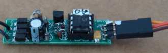
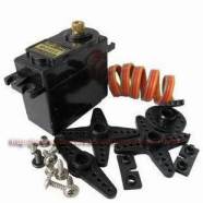
This module
controls 1 Servo. The following images show different servo
brackets available on the web and nearly all of them require a
limited angular movement. Normally a servo rotates about 270 degrees
but the bracket requires less than 45 degrees.
You just need 9v to 12v DC to operate
the module.
changing when the points are changed. In most cases you only need one micro-switch to change the polarity of the frog. The servo moves very slowly by controlling the pulses to the electronics inside the servo.
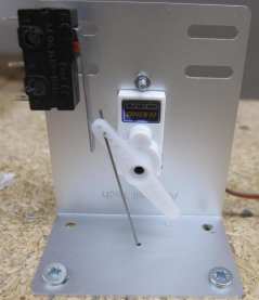
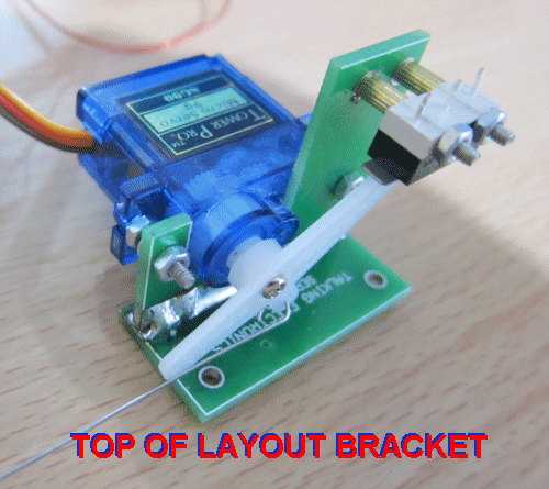
Servo Brackets are available for $2.50 usd. You must specify if you want above layout bracket or Under layout bracket.
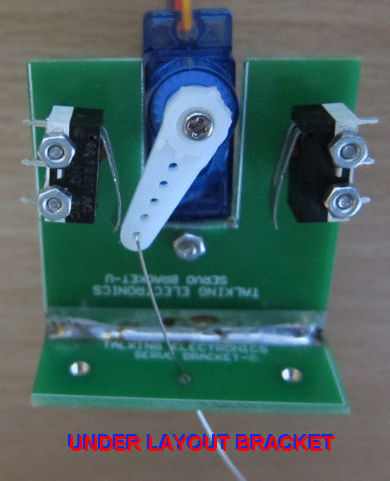 Talking Electronics bracket for under layout
This bracket comes in 2 versions. One version can be
mounted above and the other below the track.
The control wire for "Under Layout"
bracket is very thin spring steel and the activation is designed
to "overshoot" and allow the spring in the wire to hold the rail
in position.
Buy Point Controller using Motor/Gearbox $18.00 plus $8.50 post oooooooooooooooooo0000000000000000000oooooooooooooooo
CHOICE NUMBER 30:
POINT CONTROLLER
The project comes complete and fully wired with 2 converted servos on two metres of twin lead. The front panel shows the position of each point via LEDs and the toggle switches select the position of each point. The position of the point is shown by 2 LEDs on the module with an outline showing the track with siding. This makes it easy to see the position of the point. The converted servos only travel 90 degrees or less and you can adjust the travel by altering the output voltage of the Automatic pre-voltage module. This module needs a supply from 9v to 20v and it outputs a constant voltage, set by the 10-turn pot on the module. To reduce the voltage, turn the screw a very small amount clockwise. You can measure the output voltage with a meter as the adjustment is very sensitive. The converted servos are called a MOTOR AND GEARBOX and come with a spring-steel "push-rods" that also acts as a lever when you are fitting (the motor and gearbox) under your layout. The holes in the "arm" allow different "throws" to be achieved for both top and under your layout. Holders for the motor are available from Talking Electronics for $2.50 each and come with screws to hold the servo and for mounting the bracket. Use the tiny screws provided to hold the face-plate in place and the small screws to hold the arm onto the output shaft of the gearbox. You can input AC or DC to the pre-voltage module and the current-limiting resistors are needed to prevent the supply module being overloaded and the other limiting resistors allow the motor to be fed for a longer period of time to achieve the desired rotation. This is the only module on the market with these features. ooooooooooooooooo0000000000000000000oooooooooooooooo
Point
Controller for 4 Motor/Gearbox $45.00usd plus
$12.50 usd shipping
This module converts 4 manual points to
remotely operated points. ooooooooooooooooo0000000000000000000oooooooooooooooo
4-POINT CONTROLLER FOR KATO POINTS
KATO DISTRIBUTION BOARD
$18.00 plus $4.50 postage
Buy Here oooooooooooo000000000000000000oooooooooooooo
FREE
THINGS !!!
|

|
ACTIVATING A POINT |
|
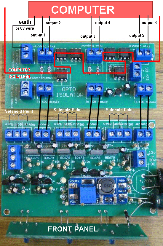
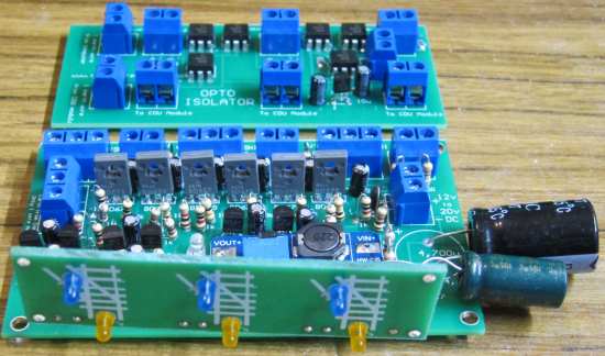
COMPUTER CONTROLLED POINTS
|
|
WIRING A POINT MOTOR |
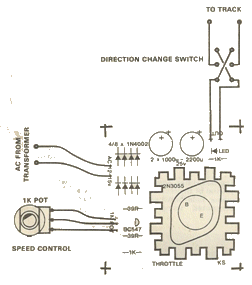
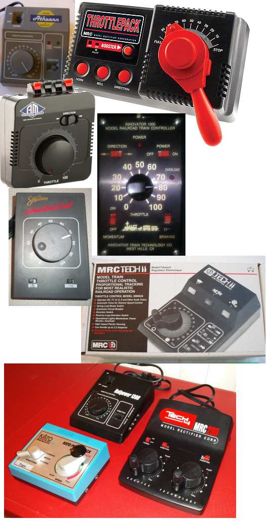
Talking Electronics has produced a number of different TRAIN
THROTTLES.
Most locos take about 300mA to 500mA and need a voltage of about 12v
for full speed.
There are two types of TRAIN THROTTLE:
The 2-Amp POWER SUPPLY project is
HERE You will need a double-pole double-throw toggle switch to reverse the train. Ask for it. $2.50 extra.
oooooooooooooo0000000000000000000000000000oooooooooooooooo
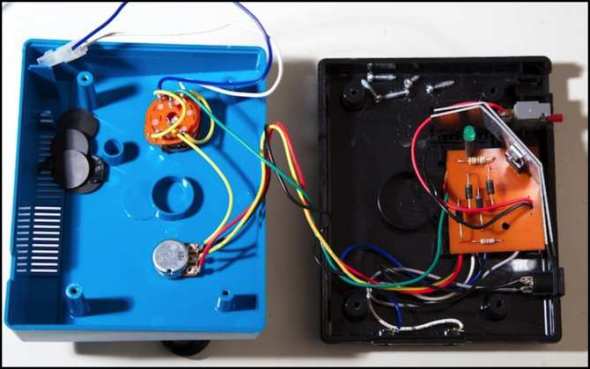
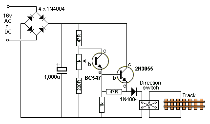
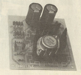
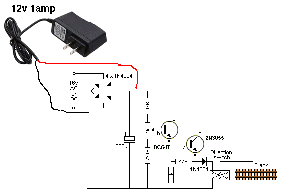
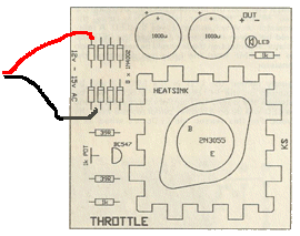
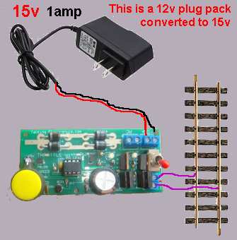
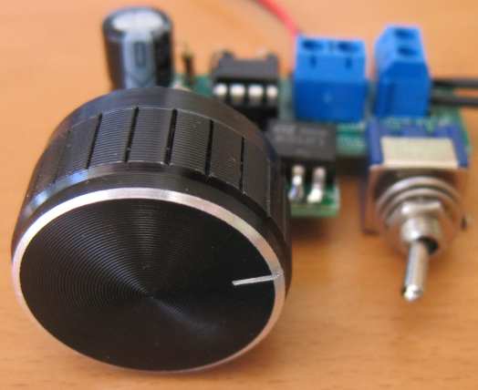
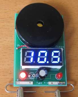
TRAIN THROTTLE No2.
(kit: $18.00 with
leads)
Click
Here
to
order.
The $2.50
plug Pack above was purchased as 12v @ 1 amp. It was easily
opened-up via a screw and clip, to reveal the PC board shown below.
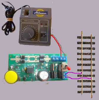
This gives you a very low cost throttle. oooooooooooooo0000000000000000000000000000oooooooooooooooo
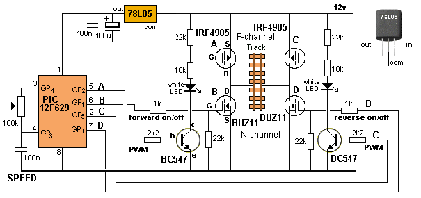
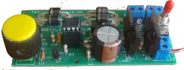
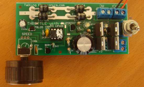
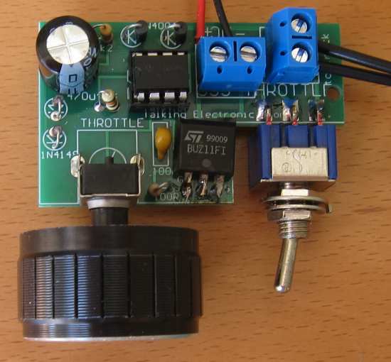
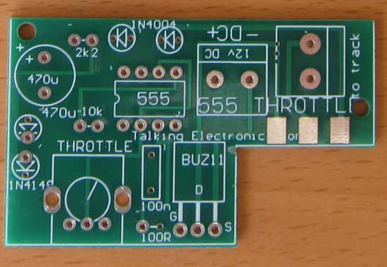
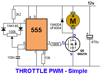
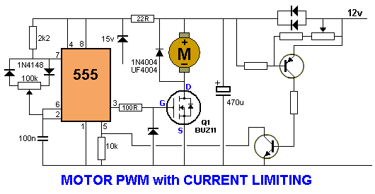
THROTTLE WITH PWM
Kit: $28.50 plus $6.50 postage.
All the
digital signals are controlled (and generated) by the
microcontroller and the pot determines the timing of the
waveform and the activation of the H-bridge. The cost is
the same for either module but you must specify which version you
want. The switch and knob are not attached when posted as the module
must be less than 2cm high for posting in the box we use.
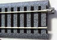
You can request the following type if you do not want to use the rail joiners:
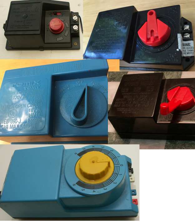
LATEST VERSION
UPGRADE YOUR CONTROLLER
Some of
the following controllers deliver just 7v and some are up to 16v AC
output and/or 16v DC output. They all have forward/reverse on the
control handle so the only improvement you will get by connecting to
the THROTTLE WITH PWM module above is PWM. PWM will allow your train
to start very slowly as the pulses overcome some of the friction by
pulsing the motor with strong bursts and this gets the train moving.
The
Transformer ooooooooooooooooo000000000000000000000ooooooooooo
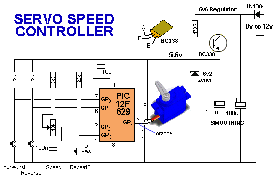
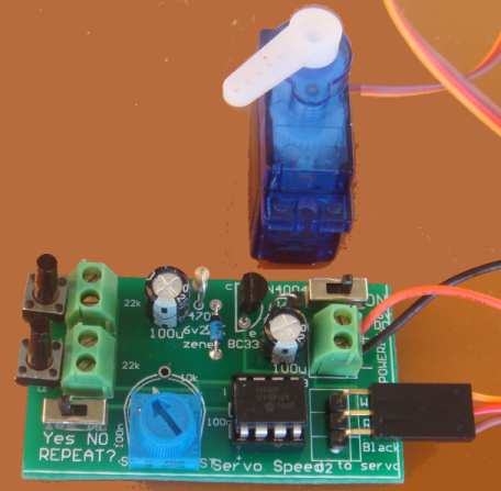
STATION
STOP
MODE 1 |

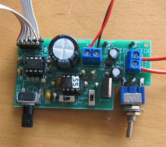
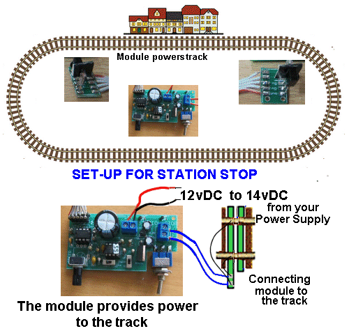
The output of
the servo moves about 70 degrees as this will give the greatest
"throw." You can select the hole on the arm to produce the travel
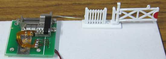
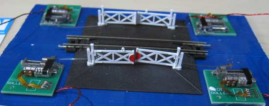
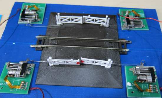
you want. Here is a set
of gates controlled by 4 servos.
|

Waiting on Printed Circuit boards. The program is written .. . . just the PCB has to be designed. Put your name on the list .
|
DCC
stands for Digital Command Control and basically means you
can control more than one train on the same track.
It
is called: DCC POINT CHANGER for a SOLENOID POINT (with CDU)
and will
operate a Peco or other solenoid point: // ????le
with a relay that you can toggle from the "5 button DCC controller"
shown above. This will allow you to operate station lighting or
motorised animation devices.
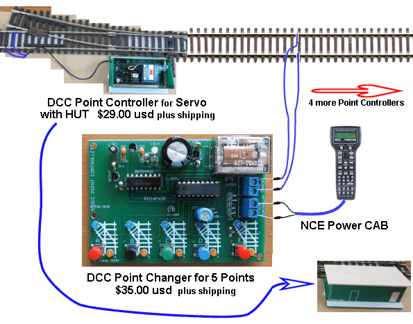
The next "add-on" is a DCC module with 5 buttons to operate 1,2,3,4
or 5 DCC points. You will need to buy the $25.00 DCC Point
Controller called a Capacitor Discharge Unit or the DCC Point for
$35.00 using a servo to operate the point. Here are the
modules in more detail:
This Dual DCC
controller will control 2 locos at the same time and is an ideal way
to create a DCC set-up. And the cost is just $43.00 AUD plus $6.50
posted worldwide.
ooooooooo0000000000000000000000000000000oooooooooooooooo
This is a 1amp decoder NOT 500mA as most of the advertised small
decoders.
You can turn
a DC Loco into a DCC loco with this universal Motor Decoder for
$18.00 plus $4.50 postage worldwide.
Converting AC Locos Here is a
video showing how to fit a bridge rectifier to deliver pulsating DC
to the filed winding:
The only
problem with fitting a bridge rectifier is this: At low velocity
the energy delivered to the field winding will be very small and
thus the motor will be very weak. The decoder delivers pulses of
energy to the motor and the pulses are actually at full strength but
for a short period of time. You can put 100u to 1,000u electrolytic
across the field winding to see if it improves the performance. |
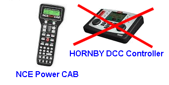 All
our modules work with NCE Power CAB and all controllers that
conform to NMRA signals and codes.
All
our modules work with NCE Power CAB and all controllers that
conform to NMRA signals and codes.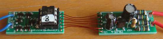
|
DCC
POINT CHANGER using a servo
You need 4
things:
You will also
need a connection to the track to pick-off the signal< to operate
the DCC Point Changer and also power the servo.
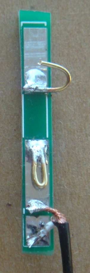
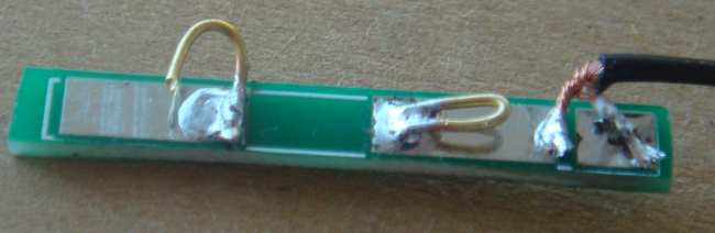
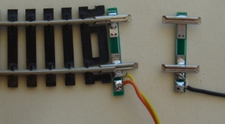
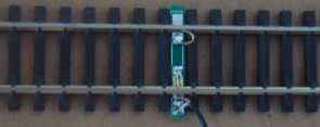
Track Pick-Off MkII.
It
has two springy clips that touch the inner parts of the rails and
make electrical contact. .
YOU
NEED 3 THINGS
SIGNAL PICK-UP oooooooooooooooo000000000000000000000000000000ooooooooooooooooo
DCC
POINT CHANGER for a SOLENOID POINT
The module takes a small amount of current from the track to charges
the 4700u electrolytic to 25v. .
ooooooooooooooooo0000000000000000000ooooooooooooooooo
Your controller
connects to the module
This module fits between your controller and the track. |
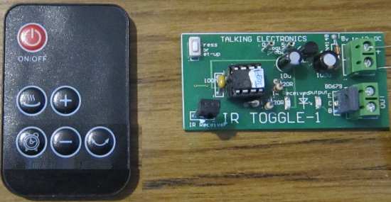
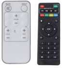
This projects
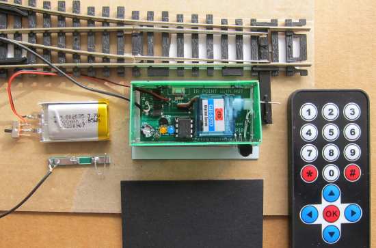
allows you to use any old IR remote control from a TV or VCR to
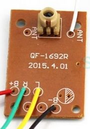
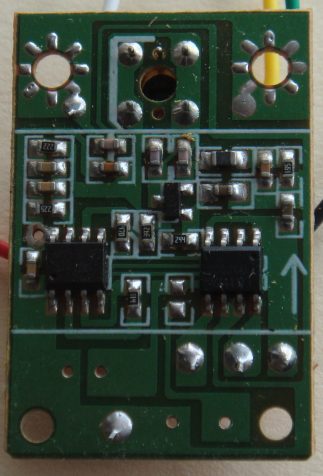
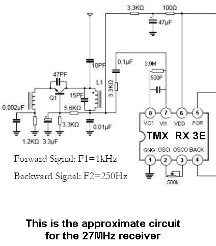
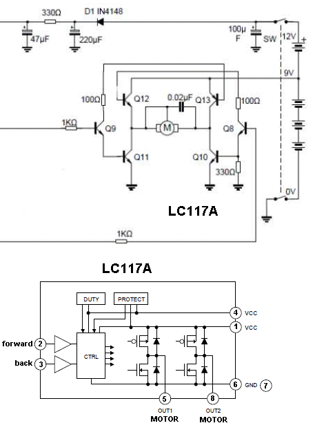
control your points.
You can walk around your layout while someone is driving your train
and control the destination of the train.
18/8/2022 |
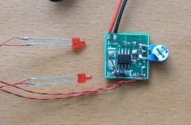
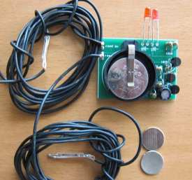
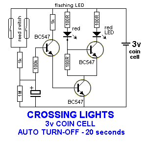
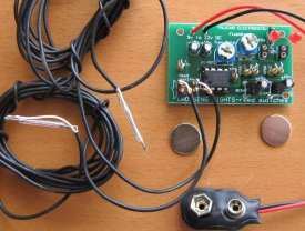
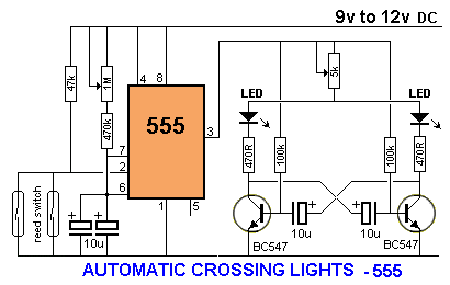
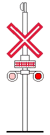
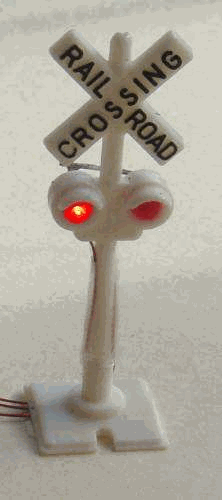
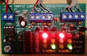
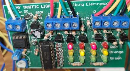
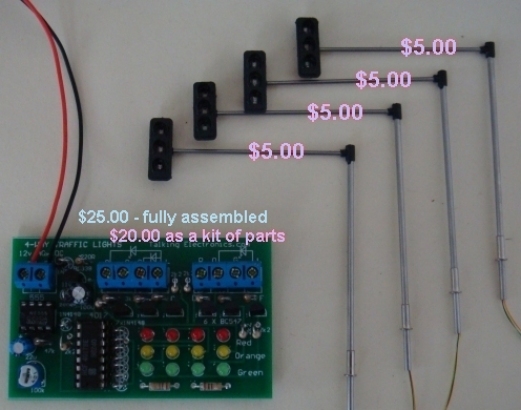
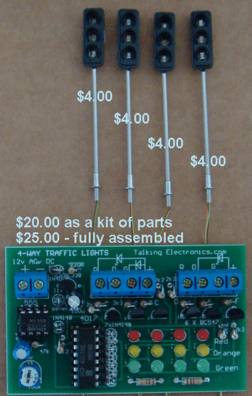
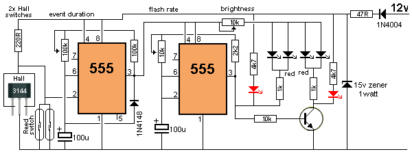
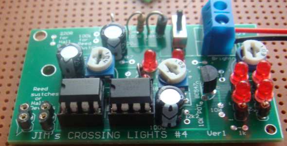
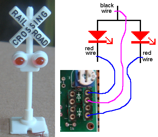
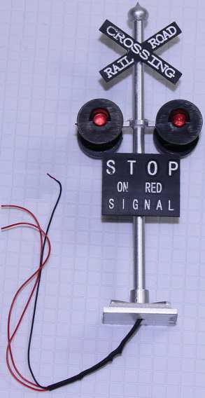
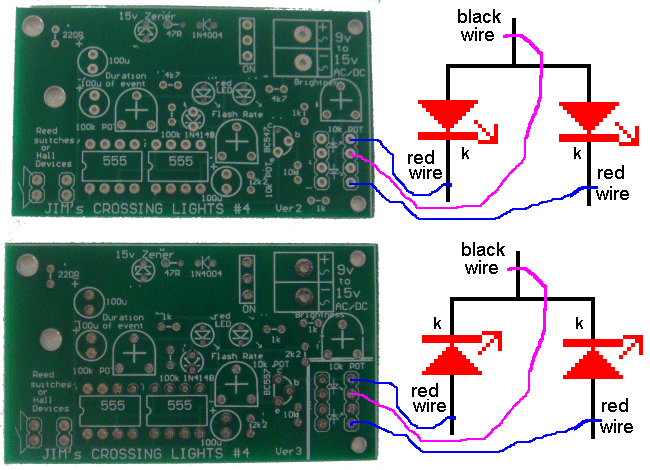
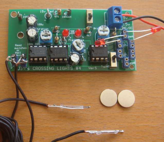
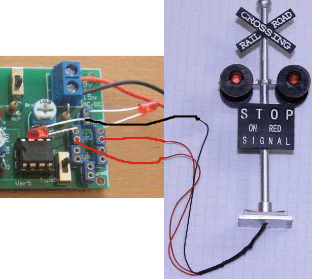
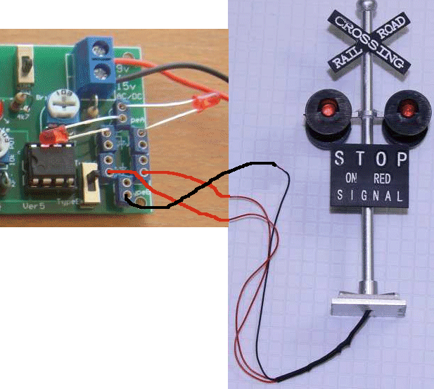
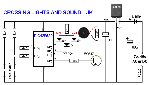
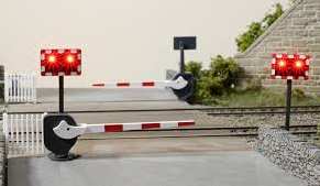
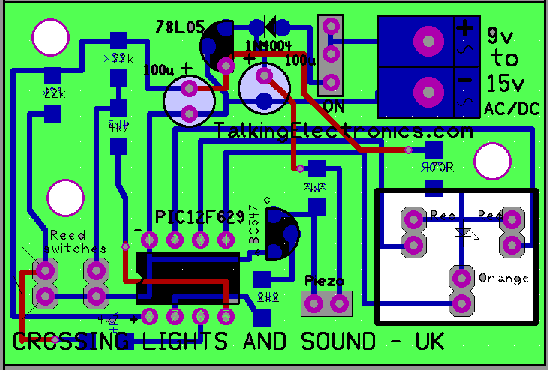
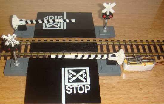
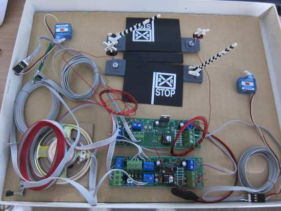
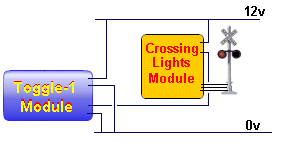
We have
designed 4 different CROSSING LIGHTS MODULES to cover the
different requests from customers.
|


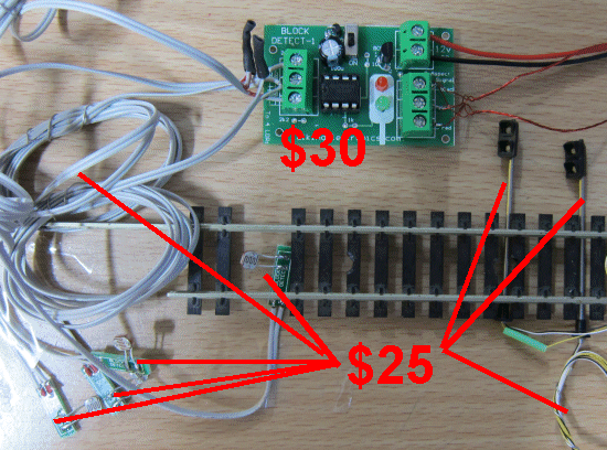
There are 10 different LOCO STOP modules, with different
prices and different features, but they all do the same thing.
|
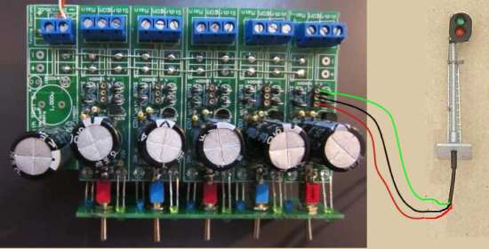
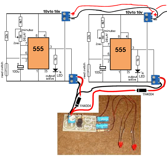
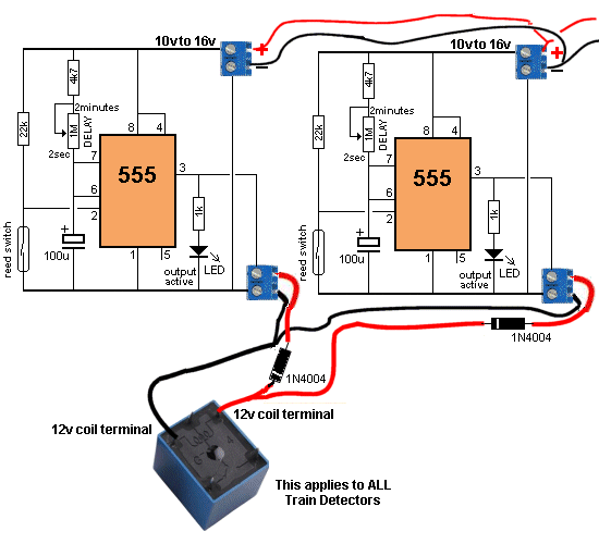
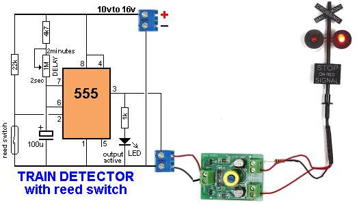
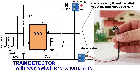
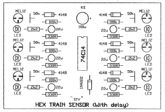
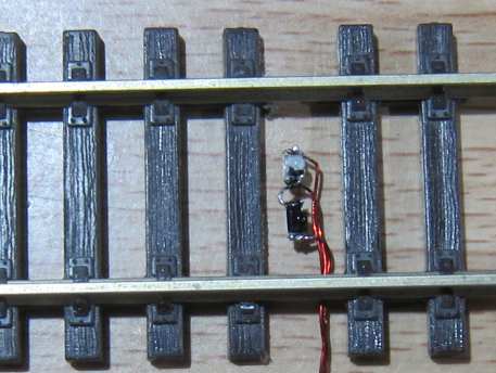
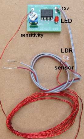
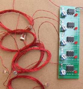
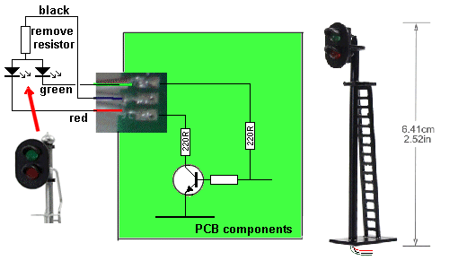
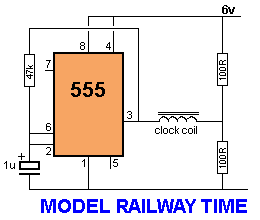
|
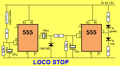
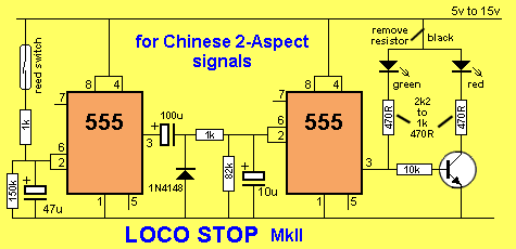
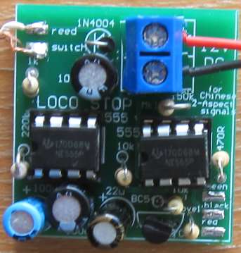
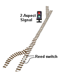
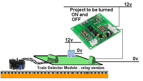
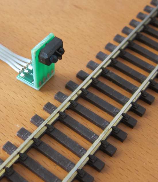
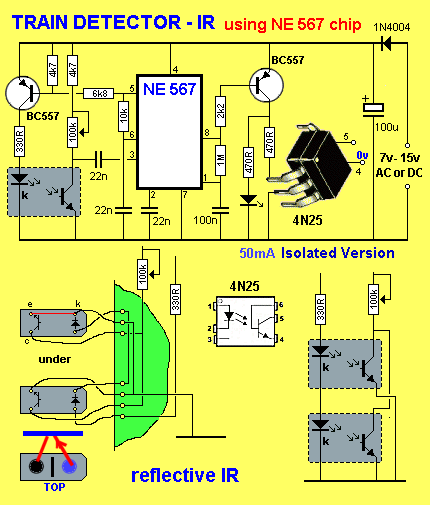
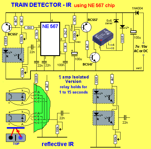
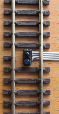
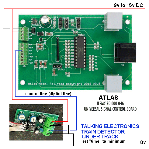
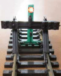
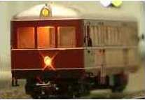
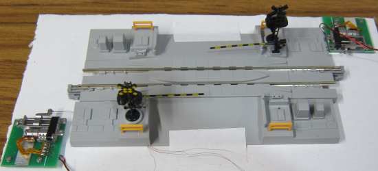
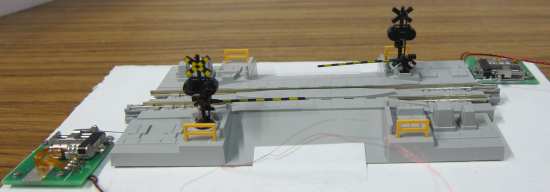
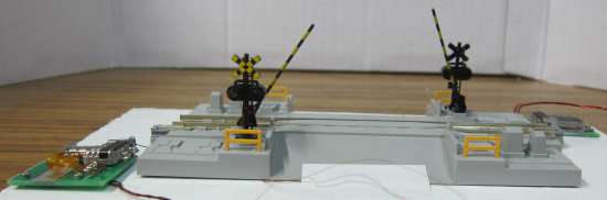
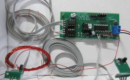
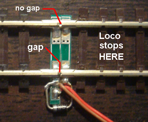
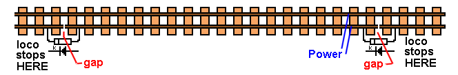
LOCO STOP
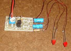
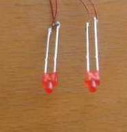
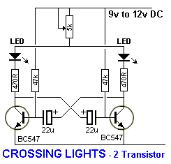
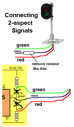
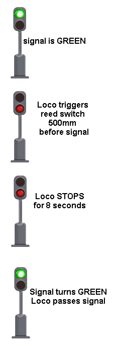
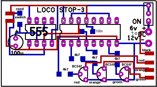
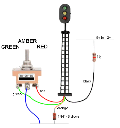
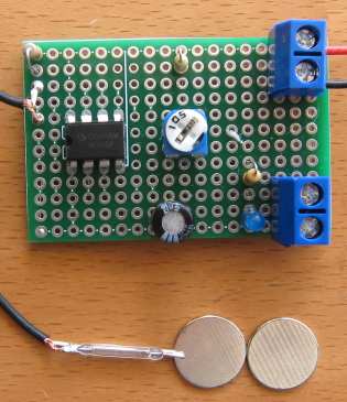
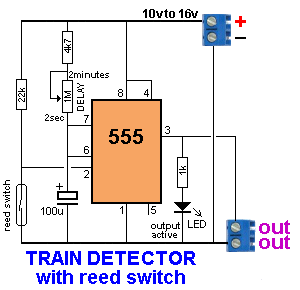
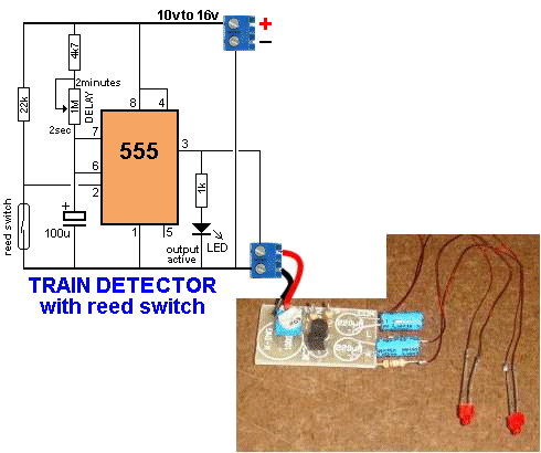
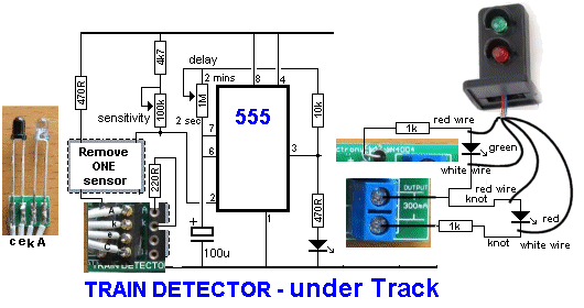
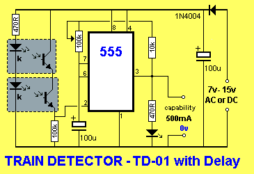
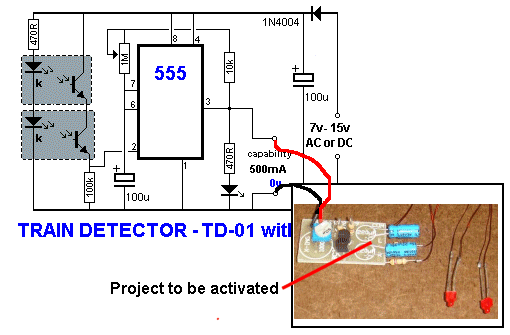
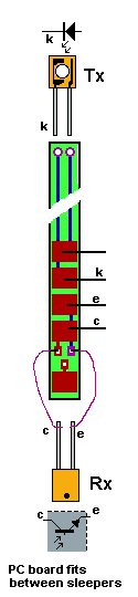
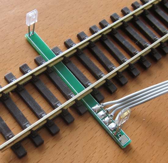
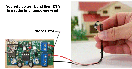
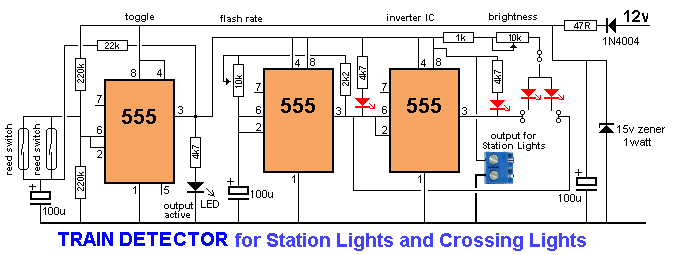
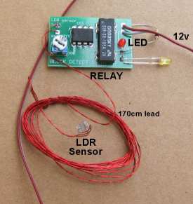
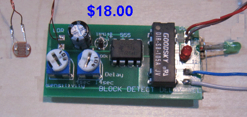
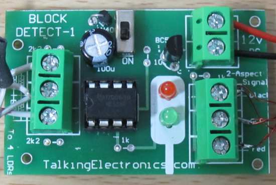
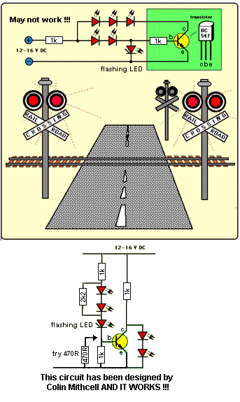
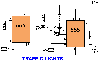
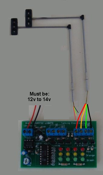
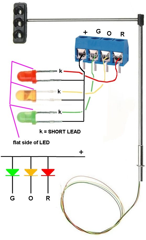
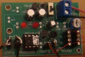
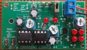
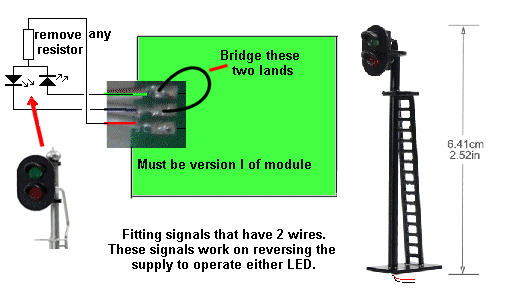
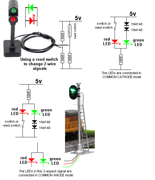
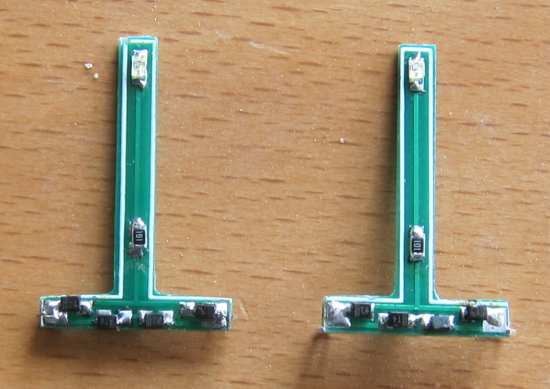
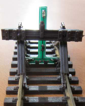
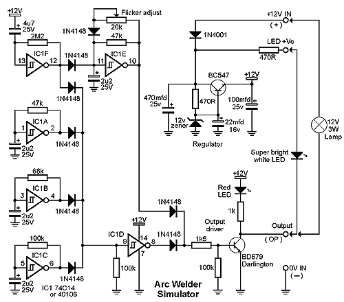
The signal is normally red and when the loco activates the reed switch, the first 555 produces a timing of about 10 seconds so the loco has to stop and wait at the signal and when the time has expired, the second 555 is triggered and the green light shows for 10 seconds and then the red appears again. All this has been done with 2 x 555 IC's. The 2-aspect signal is not a normal signal but comes as a kit from Talking Electronics for $5.00 usd as the LEDs are connected differently to standard models.
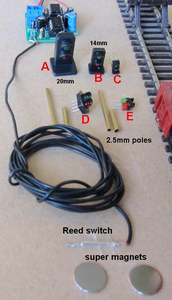
The reed switch is placed a short distance in front of the signal so the loco has to stop and wait for green. You can add an accident or track-repair after the signal to provide a purpose for stopping the train.
LOCO STOP
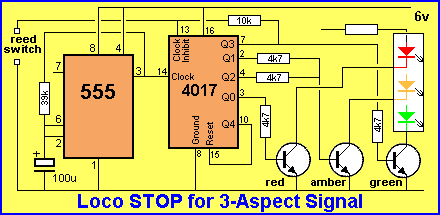
for a 3-aspect signal.
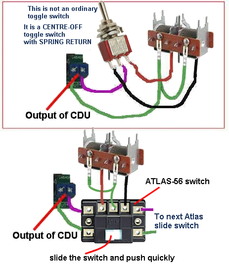
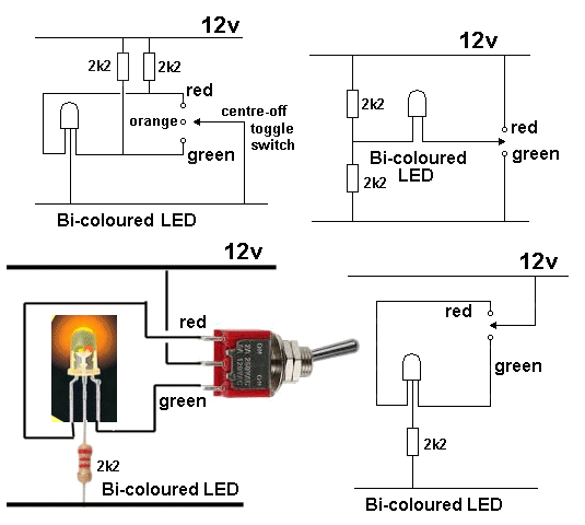
Operating 3-Aspect signal with centre-off
toggle switch
|
|
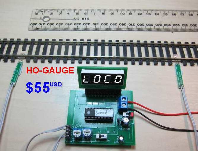
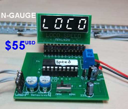
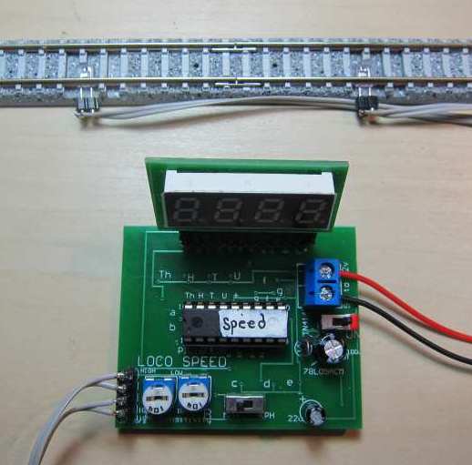
LOCO
SPEED ($55.00usd)
$85.00aud
Plus postage $8.50
|


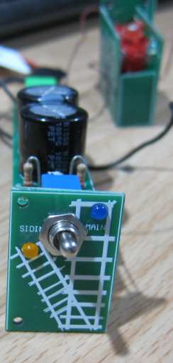
 The
control board contains two switches and two LEDs to show
the position of the point.
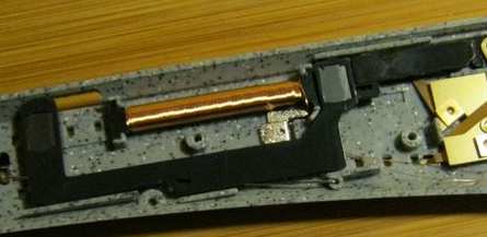
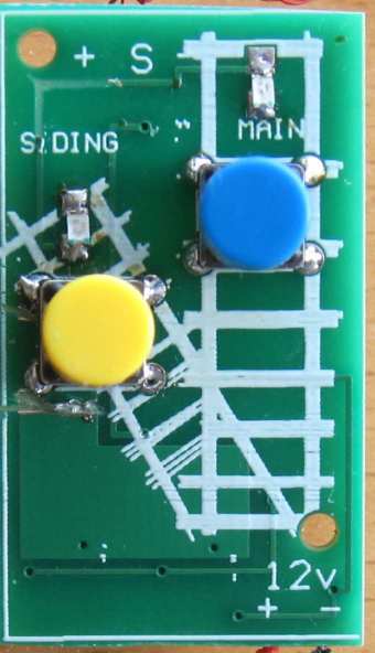
The
control board contains two switches and two LEDs to show
the position of the point.  The
N-Gauge Manual Point Controller Module
can be used to control a point for a loop of any
"siding."
The
N-Gauge Manual Point Controller Module
can be used to control a point for a loop of any
"siding." 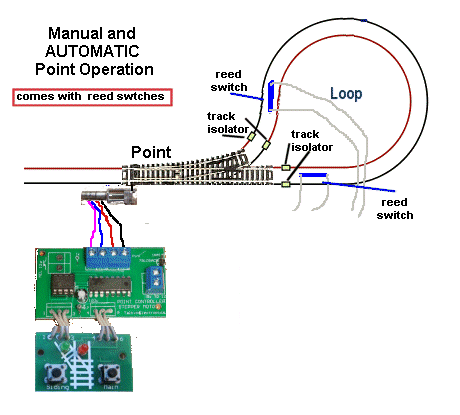 This
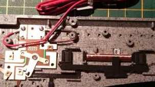
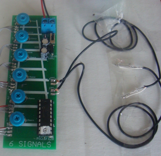
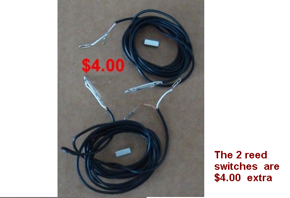
layout shows the position of the reed switches to
control the point.
This
layout shows the position of the reed switches to
control the point. 
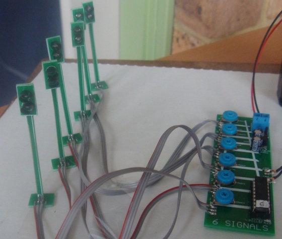
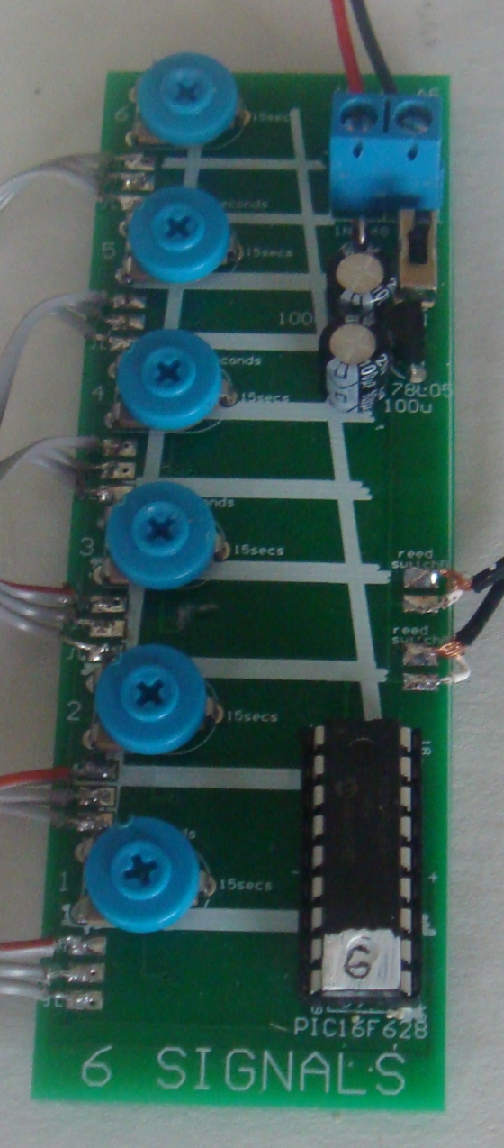
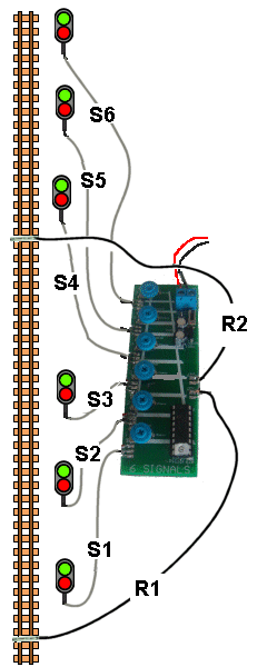
 The
signals need to be placed so that S! S2 S3 follow each other
and S4 S5 S6 follows at some other part of the layout.
The
signals need to be placed so that S! S2 S3 follow each other
and S4 S5 S6 follows at some other part of the layout. 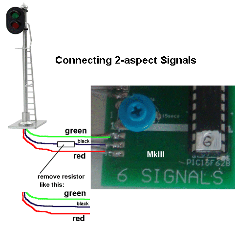
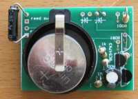
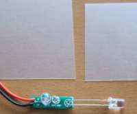
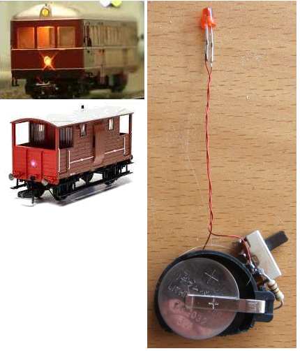
 No
batteries or supply needed. The Buffer Warning Lamp
gets its power from the rails via two springy terminals.
No
batteries or supply needed. The Buffer Warning Lamp
gets its power from the rails via two springy terminals.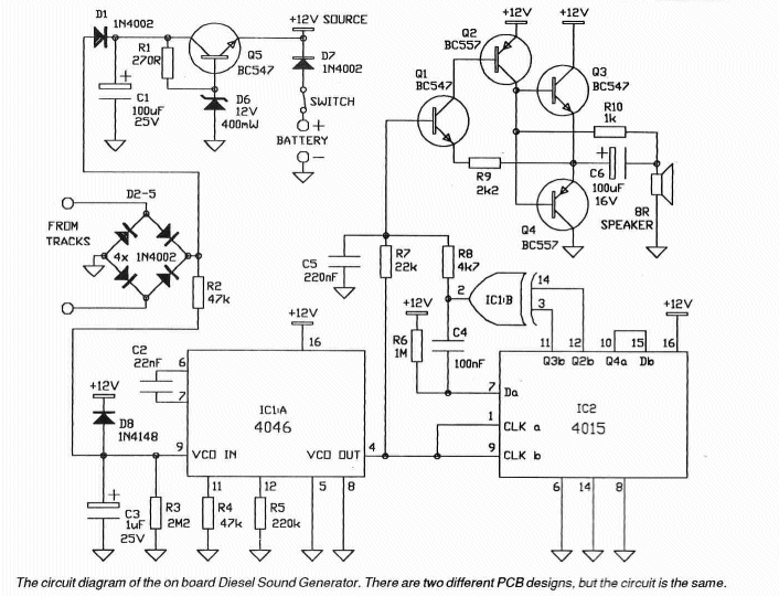
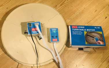
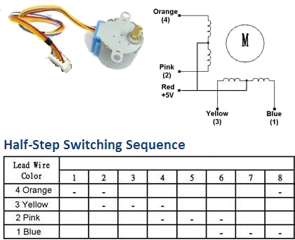
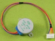 You
need to buy the 28BYJ-48 DC 5V Reduction Step Gear
Stepper Motor from AliExpress for about $3.00 including
shipping from a supplier such as:
You
need to buy the 28BYJ-48 DC 5V Reduction Step Gear
Stepper Motor from AliExpress for about $3.00 including
shipping from a supplier such as: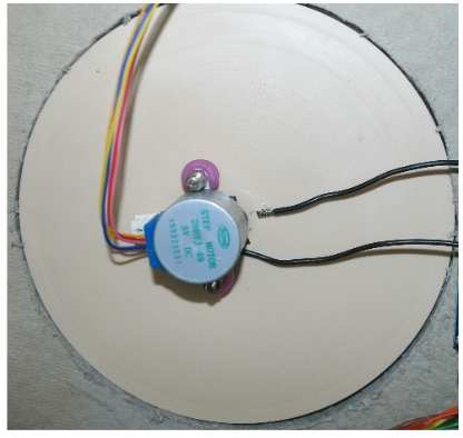 You
will need screws to hold the stepper motor as shown in
the picture opposite.
You
will need screws to hold the stepper motor as shown in
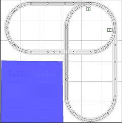
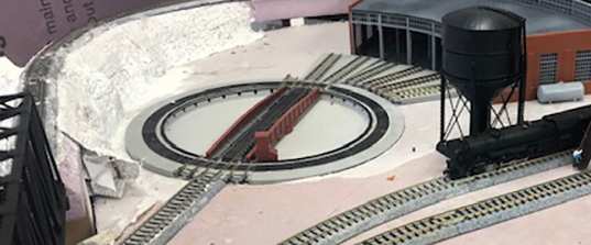
the picture opposite. 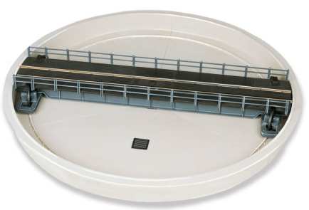 This
is the PECO turntable.
This
is the PECO turntable.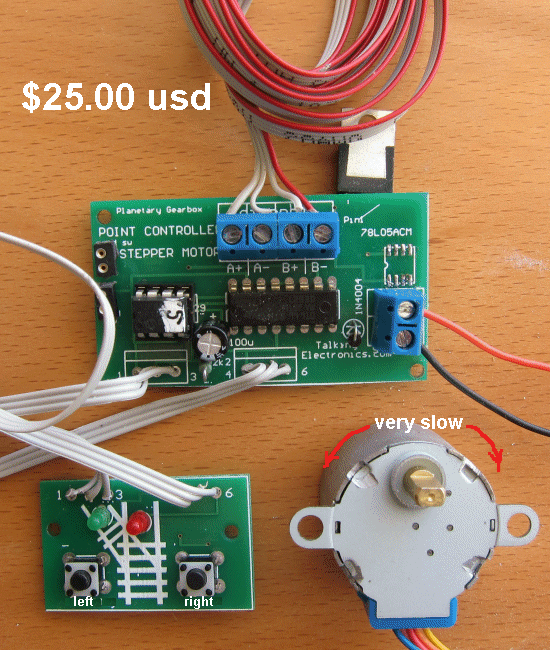


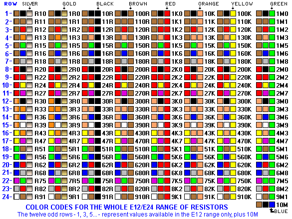
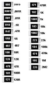
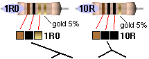 If
3rd band is gold, Divide by 10
If
3rd band is gold, Divide by 10