|
LED |
|
|
Don't Laugh.
When you are building lots of circuits and using surface-mount LEDs, there are many times when you have to test a LED to determine the cathode and identify the colour.
You may also need to compare the brightness as some LEDs are TOO BRIGHT and others are very weak.
I have even had the case where one end of a surface mount LED was not soldered correctly and did not illuminate. I had to determine if the LED or the joint was faulty.
That's why this little project was born.
The tester delivers only about 5mA to 7mA and this will help compare high bright LEDs from poor-quality LEDs and also any LEDs that have been damaged due to over-heating/soldering.
One of the big problems with surface mount LEDs is their susceptibility to damage when being soldered. They are more-sensitive than transistors!
I have never damaged a transistor but some LEDs fail after the best attempt at soldering.
That's because the light-emitting chip is only a millimeter from the lead being soldered.
This tester will identify all these problems and it only costs a dollar.
Some of the old LED testers only tested loose LEDs with a current of 1mA, 10mA and 25mA, but this tester will test LEDs in-circuit as well as surface mount LEDs.
This is the first handy piece of TEST EQUIPMENT for LEDs and there will come a time when you wish YOU HAD IT.
The tester also has two more features.
It will test a shorted LED and continuity of tracks.
The LED on the tester will illuminate when the probes touch each other and this proves the batteries are connected. This feature can also be used as a continuity tester and will also illuminate LEDs very faintly through the driver-resistors on the circuit you are testing. So, it has many uses. Just add it to the range of TEST EQUIPMENT designed by Talking Electronics and you will be ready for designing and testing all sorts of projects.
Digital Multimeters (DMM's) will illuminate all types of LEDs (with positive coming out the positive lead) but analogue meters using a single cell will not illuminate any LEDs. But they will not illuminate two LEDs in series and many of the projects we design have two LEDs making a segment of a 7-segment display.
The earth lead is negative and the tip of the probe is positive.
That's why you need all types of test equipment.
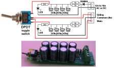
THE CIRCUIT
When a LED on the PC board is illuminated, it will drop between 1.7v and 3.6v due to the characteristic voltage drop across the LED (according to the colour). This leaves only 0.9v to 2.8v for the voltage across both the 470R and 330R resistors, as they are in series. Since both resistors are about the same value, the voltage across each resistor will be about 1.4v and this is not sufficient to illuminate the red LED. A simple but clever way of turning off the red LED when a LED is being tested. It only turns ON when a short-circuit is present.
This tester can also be used to test continuity.
It was used recently to determine the connections on a PC board from a surface-mount 8-pin PIC chip to the 5 programming pins. The LED on the tester illuminated when connected to the ends of a track. The adjacent pins were also tested to see if any tracks were shorted to other tracks.
Just another use for this handy tester.
CONSTRUCTION
A kit of components is available from Talking Electronics.
All the components are included in the kit and everything is identified on the board.
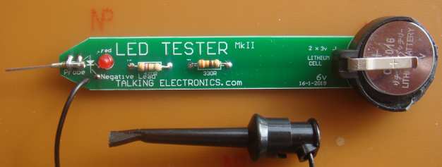
This is our new design with a lithium cell holder and 2 cells. Note the end of the holder has been broken away to make it easy to remove the cells.
The probe is a very long wire-wrap pin and a machine pin. Solder these two together and then to the board.
PARTS
LIST |
|
1 - 330R resistor 1 - 470R resistor 1 - 3mm red LED 1 - probe 1 - paper clip for earth lead (or black alligator clip) 1 - 30cm black hook-up wire 2 - coin cells - 2016 1 - coin cell holder 20cm very fine solder 1 - LED Tester MkII PCB |
(buy a number of kits and pay
TEST
EQUIPMENT
Talking Electronics has a number of pieces of TEST EQUIPMENT to help in
the design and testing of projects.
Of course you can use a multimeter for most of the testing but some of
the "tricky" faults need a special piece of equipment.
You may only need a LOGIC PROBE once a month, but the project you are
designing will come to a
stand-still if you can't locate a problem.
We designed all these projects because we needed them ourselves.
Add one of them to each order you place with Talking Electronics and eventually you will have the whole
range.
CONTINUITY TESTER
Only responds
to resistance less than 50 ohms.
Ideal for digital projects as it tests connections
very quickly.
$12.50 plus $6.50 post
(buy a number of kits and pay
only one postage)
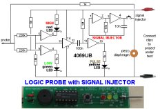
LOGIC PROBE with PULSER
- slimline
Detects HIGH and LOW
signals on both TTL and CMOS circuits.
The piezo allows you to hear low frequency signals
and the signal injector (Pulser) will over-ride
clock signals to make a circuit operate at a reduced
frequency.
$8.00 plus $6.50 post
SUPER PROBE
20 different functions.
See article for the complete list of functions.
$18.00 plus $6.50 post
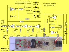
COMBO-2
TRANSISTOR TESTER
Tests transistors and shows the
gain of the transistor.
Also has Signal Injector probe.
$21.50 plus $6.50 post
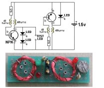
Simple
Transistor and LED Tester - 3
Tests PNP and NPN transistors and LEDs.
Also teaches the amazing property of an air-cored
coil in producing a high fly-back voltage.
$4.00 plus $3.00 postage.
(buy a number of kits and pay
only one postage)
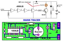
MAINS TRACER
Detects 240v AC mains hidden in walls etc.
Will also pick up RF signals from a keyboard to show you where
Electromagnetic Radiation is coming from and giving you a headache.
$10.00 plus $4.50 post
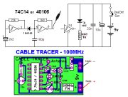
CABLE TRACER
- 100MHz
Traces cables when the power is OFF.
Uses an FM radio to pickup beeps.
$10.00 plus $4.50 postage.
only one postage)
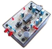
OP-AMP TRAINER and TESTER
Teaches how an op-amp works by using pots to control
the voltages on the two inputs.
$24.50 plus $6.50 post
(comes with instructions)
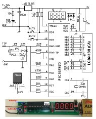
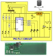
PIC Fx-1 MICRO (8 pin) PROGRAM DEVELOPER and TESTER
Learn to program PIC chips.
Comes with a pre-programmed PIC12F629 chip with 3 routines.
$12.00 plus $6.50 post
model railway
POINT MOTOR CONTROLLER and TESTER
CDU-Inline
The cheapest CDU project you can get.
$8.50 plus $6.50 post