PEN BUG MkIV |
A bug small enough to fit inside
a marker pen.
The
LED
Power Meter can be used to detect the output
and
Field Strength Meter
MkII will help produce the best output.
Kits are available from Talking Electronics.
![]()
Our Pen Bug projects have been very popular.
The idea of being able to hide a transmitter in a pen is very appealing. In an
effort to reduce the size of this design, we have used surface-mount
components.
PEN BUG CIRCUIT
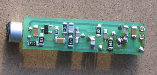
![]()
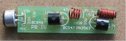
Topside of Pen Bug MkIV
Our first Pen Bug circuit appeared in our book: "More FM Bugs" and the Mkll modification
was presented in "Security Devices." The only difference between these was the
antenna arrangement. In the Mkl version the antenna was wound in a spiral and
fitted into the barrel of the pen. In the Mk II version a tank circuit was
added and the coil of the tank circuit used as an active antenna.
Our Pen Bug MkIII out-performed the earlier models where the antenna was
longitudinally wound and coupled between two stages via the emitter of the
oscillator.
Firstly, the thought of using the coil in the tank circuit for transmitting RF was a little far fetched, but we used it as an example for those
who were interested in experimenting with our circuits.
Now we have gone back to a conventional antenna, the whip. The whip or
straight-line antenna can be coiled, wound longitudinally or folded. The
way it is wound makes a big difference to its effectiveness, but when you are
limited in space, you have to accept these limitations.
Even though we have used this antenna set up in our previous pen bugs we have
considerably improved the circuit to the point were it has low battery
consumption, but high RF output.
The size of this design has been reduced considerably by using surface-mount components.
From the outset let me say it is very difficult to get a good range from a
bug fitted inside a pen.
As you can imagine, it is practically impossible to have an antenna with any
effectiveness when inside a pen barrel. We
got about 10-15 metres under good conditions.
|
PARTS LIST |
|
1 - 390R (marked 391) |
CONSTRUCTION
Before starting the assembly, it is important to have everything ready with the parts laid out on your workbench for easy identification.
The surface mount capacitors are going to be the most difficult to
identify as they don't have any markings and the size is no indication of the
value. The only way to identify their value is the order in which they come in
the carrier strip.
Refer to the following diagram for the placement of the capacitors as well as
the resistors:
Underside of Pen Bug MkIV
showing the surface-mount components
For a comprehensive guide to soldering surface-mount, read the article on this
CD: "Soldering Surface Mount", and the construction notes for the
Micro Bug, as these will give you further guidance and extra
information.
Fit all the surface-mount components first. Then the two transistors and coils.
Make sure the enamel is scraped off the
leads before fitting by using a sharp blade or file or sand paper. The most
convenient way is to remove the enamel by applying a fair amount of solder to
the iron tip and hold it to the wire until the enamel bubbles
off, leaving the copper wire tinned.
Don't squash the turns of the coil together as they may have to be stretched apart during
testing, for setting the frequency.
Now the board is now ready for the microphone, switch and batteries.
You can solder directly to the button cells if you firstly scrape the top and
bottom with a blade or file. This will roughen the surface so the solder will
stick. Make sure the soldering is carried out very quickly otherwise the
seals on the cells will be damaged and they will leak. These chemicals are very corrosive, so be careful.
The microphone needs two short lengths of tinned copper wire soldered to its
lands so it can be connected to the board. The microphone is polarized so
it must be connected the correct way. The negative lead of the microphone goes
to the case.
The
negative rail of the project is the copper strip that runs the length of the
bottom of the board and meets the negative terminal of the battery. The
microphone must be soldered very quickly otherwise the FET inside the case will
be damaged and it will lose sensitivity and produce a lot of back-ground noise.
The only thing we haven't provided in the kit is the case.
This has been left up to you as there are so many different types of pens and markers that will hold the project. It is preferable to use an old, dried out marker as this will save you a couple of dollars and you don't have to handle any messy ink.
If you want the pen or marker to write normally so that no-one will suspect the contents, you will have to provide a section up the front to hold the pad of ink and this will have to be sectioned off from the rest of the barrel to prevent the ink drying out.
The main aim is to get a case that will fit the board, batteries and switch. After this you can see how much room you have for the ink.
Next you will have to work out the switch arrangement and it can be either a slide switch mounted inside, a pressure switch kept apart with a pin or a reed switch kept open with a magnet on the outside of the case.
When the pin is pulled out or the magnet removed, the switch closes and the bug is activated.
The Commercial bug (as explained the MkIl article) did not have a switch. Two button cells were fitted into the barrel and the cap screwed on. The bug was then active and would operate for about 8 hours. The idea is to arm the bug before-hand and leave it at a meeting etc. Later you can go back and pick it up.
The bug we saw was actually a ball-point pen and the ink was contained in a refill near the tip. By the time we got it, the ink had run out and the only telltale difference was the larger-than-normal barrel and extra weight. Anyone with a fair degree of intelligence would become suspicious at the extra size and wonder why the pen is so cumbersome.
You could not see the hole at the end for the microphone and no external antenna was used.
MEASURING THE OUTPUT
It is essential to be able to measure the output without physically touching any part of the circuit and this is why we use the Field Strength Meter MkII. Coil a sheet of paper around the board and hold it in place with sticky tape. Coil the antenna wire on this paper former and space the turns. By adjusting the position of this antenna, you will be able to get the maximum output.
Place the board inside a marker pen and finally test it for both range and clarity.
When you are satisfied with the results, fit some small pieces of foam to prevent the board moving around and fit the pen tip. Now you are ready to try it out. Ask someone to use your “Pen” and see if they notice anything different. Don't let them know or they'll want one too!
1-9-2010