This eBook shows you how to
TEST COMPONENTS.
Use your "brain, knowledge
and your fingers."
To do this you need "TEST GEAR." The best item of
Test Gear is a
MULTIMETER. It can test almost 90% of all components. And that's what we
will do in this eBook.
This eBook has been translated into Azerbaijan language by
Safa Macidov
Here is the link.
Sometimes you can fix something by letting it run until it finally
fails.
Some things start to work as soon as you touch them.
Some things can never be fixed.
But some things can be fixed by feeling the temperature rise and
deciding if it is getting too hot.
Sometimes you can smell something getting too hot.
Sometimes you can see SMOKE.
All these things make you a very clever technician and about 50% of
faults will be fixed by looking for dry joints, burnt parts, overheating
and carefully inspecting an item before you disturb it.
By simply touching different items you can quite often feel a hot item
and home-in on the fault - at a saving of hours of work.
Servicing is not "A bull at a gate" approach.
You may be able to service something by turning it on and leaving it for
hours - and start thinking.
It may take you a day to come up with the answer.
Believe me. That's how it worked for me - while fixing over 35,000 TV's.
But that was in the days of valve TV's and individual parts, soldered
from one tag strip to another.
Things have changed now. Parts have become smaller and everything is
soldered to a printed circuit board. And we have simple chips and
complex chips and microcontrollers and power chips.
So, you need to be a lot smarter. You need to be very careful when
"poking around," and you need a couple of very simple pieces of test
equipment. Starting with an Audible Continuity Tester and a Logic Probe.
But firstly this article covers and explains lots of interesting
features about testing components so you know what to look for when
fixing a piece of equipment.
A reader sent me an email: What University course do I apply for,
to get an electronics degree?
My answer: Before you start to waste $30,000 on a course, read all of
Talking Electronics website and make at least 100 of the projects.
Then go to a University and "sit in" on a lecture and see what they are
teaching.
Then go to a student who has nearly finished the course and show him
some of the reasonably-complex projects you have made and ask him some
simple questions.
You will be shocked.
TEST EQUIPMENT
Everyone thinks TEST EQUIPMENT will "solve the problem."
This is a big big MISTAKE.
Test equipment can help solve a problem and it can "lead to
frustration," "give an incorrect answer," "mess you up," and
make things worse.
You have to be very careful with test equipment and especially EXPENSIVE
equipment because it is very sensitive and can detect pulses and
glitches and voltages that are not affecting the operation of the
circuit.
You will learn a lot of tricks when reading through this article, but
let me say two things.
There are lots of faults and components that you cannot test with "test
equipment" (either In or OUT of the circuit) because the fault is either intermittent or the equipment does
not load the device to the same extent as the circuit.
And secondly you need both an ANALOGUE multimeter and a DIGITAL meter to
cover all the situations.
And if you are working on a car, you only need a $5.00 analogue meter
because it will be dropped or fall into a crack, get oily and dirty and you will only lose
$5.00
You will learn that a digital meter will pick up spikes and signals on a
line and show an incorrect reading.
That's why you need to back-up your readings with an analogue meter.
When you charge a battery it gets a "floating voltage" and this will be
higher than the actual voltage, when the battery is fitted to a project.
An analogue meter will draw a slight current and remove the "floating
voltage" after a period of time.
Component testers can also give you a false reading, either because the
component is out of range of the tester or intermittent and you need to
be aware of this.
Oscilloscopes can also display waveforms that are parts of glitches or
noise from other chips and these do not affect the operation of the part
of the circuit you are investigating.
Sometimes you cannot pickup a pulse because it is not regular and the
trigger on the oscilloscope does not show it on the screen. You may
think it is missing.
It all depends on the "speed of the oscilloscope" - it's maximum
frequency of operation.
Lastly- Power Supplies. You cannot test globes and motors on a
power supply because the starting current can be 5 times more than the
operating current. The power supply may not be able to deliver this high
current and thus you will think the motor or globe is faulty. Or the
power supply is faulty.
You don't have to buy expensive test equipment but you do need it to do
the simplest testing and fixing.
Here are the first four things you will need:
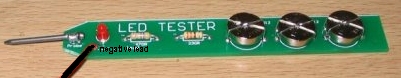
LED TESTER - tests LEDs
See the project:
HERE
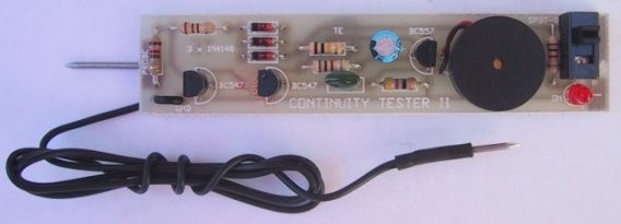
See the project:
HERE
The CRO
- OSCILLOSCOPE - DIGITAL CRO
It has very good
resolution and it needs a little bit of understanding to work out the
amplitude and frequency of the signal your are displaying.
If you want to look at
the signals in a project, you can get a low cost DIGITAL OSCILLOSCOPE
for less than $40.00, such as this:
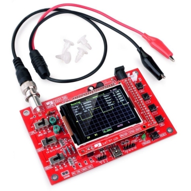
You can buy the oscilloscope on Aliexpress for about $40.00 and at the
same time buy a LED that flashes RGB (either fast or slow) so you can
use the CRO to watch the waveforms produced by the LED. Unfortunately
the flashing LEDs are only available for $7.00 for 100.
The CRO comes fully built and tested but it needs a stand so you can use
it on the work-bench. Wooden blocs 9 x 17 x 50mm are available from
$2.00 shops and if you cut the end at 20
A 9v or 12v battery is needed with a switch to power
the CRO and you are ready to see some waveforms.
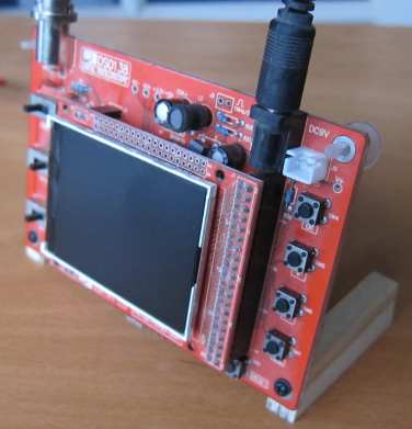
Adding a stand so you see the
screen
Firstly you need to see a waveform on the screen and a RGB slow
flashing LED has a microcontroller inside the chip that creates the
random pattern. Connect the LED to 9v or 12v via a 1k resistor and
connect the probe across the LED. The 1k resistor will allow you to see
the signal produced by the microcontroller.
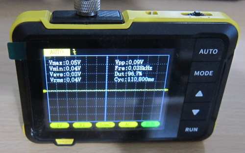
This is a much better DSO
It has internal battery and a clip-out stand

It has all the features of the other model
and a similar price
SETTING UP THE CRO
The CRO has lots of features and the challenge at the beginning is to
get a TRACE on the screen.
Firstly we will explain the terms.
The PROBE in this case is like two test leads (red and black). The
RED lead is called the TIP and the BLACK lead is called the EARTH.
The black lead is normally clipped onto the chassis of a project and the
red lead touches all the components.
Stick to this convention so the waveform is not inverted.
The top left-hand slide switch is called the COUPLING. It has 3
positions. The left position is connected to the tip of the probe and it
"shorts the tip to earth" so that the trace will be a smooth line across
the screen.
This is used in the set-up procedure so the trace can be adjusted to
travel across the middle of the screen so the amplitude of the
waveform can extend equally above and below.
The middle position of the switch connects a capacitor to the tip so
only the amplitude of the waveform will appear on the screen.
The right position of the switch connects the tip directly to the input
of the CRO and if there is any DC voltage on the waveform, it will shift
the waveform up or down the screen.
This might take the waveform above or below the screen and you will not
be able to see it, so use the AC coupling when you are setting-up.
The other two slide switches are what we call SENSITIVITY.
The input of the CRO is very sensitive and every line across the screen
is equal to a 10mV signal. There are 4 lines above the centre line
and 4 lines below the centre-line. These lines are called
GRATICULES but we will just call then amplitude lines or X-lines or
X-axis lines. They are voltage lines.
But this means the CRO will only show a waveform that is 80mV high.
To show larger waveforms the CRO has attenuation networks - resistor
networks - that reduce the incoming waveform so it will appear on
the screen.
Flick both switches to the right.
You have now selected 10mV and x1.
This means each line across the screen will be equal to a signal of
10mV.
When the bottom slide switch is in the middle position, each graticule
will represent a waveform that has an amplitude of 20mV. In other words
the screen will show a waveform 160mV high.
With the bottom slide switch to the right the screen will show a
waveform 50 x 4 x 2 = 400mv high. This still a very small waveform.
Now slide the middle slide-switch to the middle position and the full
amplitude on the screen becomes: 100mV, 200mV and 500mV per screen
division.
Finally, with the middle slide-switch to the left position, the
graticules become 1v, 2v and 5v.
This means the screen will display 80v amplitude signals.
On the right-hand side of the module are 4 press-buttons.
We start with the lower button. called
This is the button that is going to put the trace across the middle of
the screen. We say: across the Y-axis - through the "origin."
The origin is the meeting of the X and Y axis and in this case the
X-axis is the left-hand side of the screen and the Y-axis is the middle
of the screen.
Turn the module ON and press the lower button. The cursor will highlight
parameters at the bottom of the screen at each press and then will seem
to disappear. But it is highlighting the arrow at the left of the screen
and changing the arrow from yellow to blue. When it is blue, you
can move the arrow up and down the screen by pressing the second button
to make it go up and the third button to make it go down.
This arrow will take the trace up and down the screen so you can fit all
sorts of waveforms on the screen.
When setting-up, place this arrow along the Y-axis so you can see the
trace.
The trace is not a line across the screen but a dot or pixel flying
across the screen so fast that is leaves a trail that you see as a line.
The fourth button sets the speed at which this dot flies across the
screen.
The fastest time is 10 microseconds (10uS) And this is the time for the
pixel to travel from one vertical line to the next. In other words it
will take 80us to travel across the screen.
But we normally do all our calculations within one division (as you will see
in a minute). If a
waveform starts on the Y-axis (the line running across the centre of the
screen) and rises to a peak when the scan is in
the middle of the graticule and then falls to a minimum and then rises
again and meets the axis at the vertical line we say the waveform has
completed one cycle in 10us.
This is the basis of all our calculations when we determine the
frequency of the signal - the signal is the incoming wave.
Here is a table for all the frequencies:
| 10uS | 100kHz |
| 20uS | 50kHz |
| 50uS | 20kHz |
| 0.1mS | 10kHz |
| 0.2mS | 5kHz |
| 0.5mS | 2kHz |
| 1mS | 1kHz |
| 2mS | 500Hz |
| 5mS | 200Hz |
| 10mS | 10Hz |
| 20mS | 5Hz |
| 50mS | 2Hz |
| 0.1S | 1Hz |
| 0.2S | These |
| 0.5S | are |
| 1S | waiting |
| 2S | times |
| 5S | for a |
| 10S | wave to |
| .... 500Sec | appear |
SWEEP
Originally all CRO's were analogue devices and used a CATHODE RAY TUBE,
in which an electron beam was projected from the back of the tube (the
neck) onto the screen. The screen had a phosphor coating and when the
electron beam hit the screen it fluoresced and you could see the spot.
The spot was then made to travel from the left of the screen to the
right and the screen remained illuminated for a short period of time
after the beam hit the area. A bit like the tail of a comet. This gave the effect of a brightly
illuminated line across the screen.
The screen on this CRO is DIGITAL and all the effects are created by
software in the microcontroller.
So that the screen appears like the original CRO's, the software
produces a trace across the screen so you know what is happening.
We can pretend the trace is a "flying spot" and this is called the
SWEEP.
The sweep is measured by how long the "spot" takes to travel ONE
GRATICULE. That is from one vertical line to the next.
In our case this is as fast as 10 microseconds. If a wave is being
processed by the microcontroller, the "flying spot" moves across the
screen from the left-side, rises to the amplitude of the signal, moves
across the screen at the same amplitude and then falls to the lowest
point of the signal and then across the screen, to the rising edge of
the wave and continues in the same way to the right of the screen.
All CRO's have a TEST POINT (or TEST PIN) that produces a 1kHz square wave with a known amplitude. The tip of the probe touches this point and the screen displays the waveform. This allows the operator to confirm the settings on the screen are correct and the trace is in the middle of the screen.
You don't need to connect the earth lead to view this signal as the earth is connected internally on the board.
The following diagram shows 3 waveforms:
The frequency of the signals is the same (such as 10kHz) and we are only
showing one cycle to explain this feature.
The aim is to get the rise or fall of the wave so that it sits ON a
graticule so that you can count the number of cycles across the screen
and count the number of graticules.
In the image above we have six full cycles across 12 graticules. You
cannot see the rise of the first cycle but we can assume (correctly)
that it will be exactly the same as the rise of all the other cycles.
And the same applies to the last rise.
We now select 10 graticules and this means we select ten "spacings" and
in this distance we can count 5 complete cycles. This makes our
calculations easy.
So, we have one cycle in 2 graticule-markings.
Suppose the sweep is set to 10uS. If we have one cycle per graticule,
the frequency would be 100kHz. But the frequency takes 2 markings for
each cycle and it is has a lower frequency than 100kHz. In fact it is
50kHz. To prove this, you can change the sweep to 20uS and each
cycle will occupy one graticule.
SAFETY
To prevent damage to the input of the CRO, it is best to fit a 1k
resistor to the tip and use the lead of the resistor to probe the
equipment you are testing. The input of the CRO is fairly high and 1k
will not affect the amplitude of the signal.
MAXIMUM FREQUENCY
This CRO is not MHz or GHz CRO. It is a $40.00 Digital CRO for
Audio work and will detect a lot of signals on microcontroller projects
that use 1MHz to 4MHz clocking. These projects will have signals up to
250kHz and 1MHz.
The screen consists of pixels and the waveform must be one pixel wide
and one pixel spacing, so you need 4 pixels to show cycle. When the
frequency is too high, the lines are simply joined together and nothing
can be determined.
However you can detect 4 or 5 complete cycles within a graticule and 5
cycles represents a frequency of 500kHz.
Displaying the Maximum frequency
SHIFTING THE TRACE
We have covered the feature of connecting the tip of the probe to the
module by a direct link (called DC) or via a capacitor (called AC).
This is called COUPLING and is determined by the top left-hand
slide-switch.
We can also shift the trace up and down the screen to get more of the
waveform onto the screen, especially when we have selected DC coupling
and the wave is shifted up or down due to the DC offset.
DC OFFSET is the the DC voltage on some signals, where say the 12v
rail voltage is present and we want to see the ripple. You can either
select AC Coupling and see the trace across the centre of the screen or
select DC Coupling and move the trace so it can be viewed.
Moving the trace up and down is done by the
The SELECT button highlights the functions at the bottom of the screen and when it highlights the arrow at the left of the screen and changes from yellow to blue, you can move the arrow up and down the screen by pressing the second button to make it go up and the third button to make it go down.
This arrow will take the trace up and down the screen so you can fit waveforms on the screen.
DETECTING SIGNALS
There are many devices you can use to produce signals on the
screen. A simple CRO like this is not magic. It does not produce a
waveform immediately as it needs time to process the information and if
the signal is from speech, the wave will be very complex. It will
consist of large and small waves with varying duration. Clean signals
are much easier to understand.
Don't use the CRO near you laptop as the leads pick up scanning signals
from the keyboard.
Start with the signal from the TEST POINT and view it on the screen.
You can whistle into a piezo diaphragm or talk loudly into a speaker and
see the result.
You can also get a flashing or fading RGB LED and connect it a 12v
supply via a 1k resistor. Put the probes across the 1k resistor and you
will see the signal from the microcontroller.
TRIGGERING
We need the trace on the screen to be as stable as possible so we
can view the signal and work out its characteristics.
To do this there is a detecting circuit that starts to look at the wave
when it has increased by a small amount. From this the circuit will
start detecting the next cycle at the same point and at least the
beginning of each cycle will align with each other.
Waveforms that are constant and accurate are not a problem as they will
display cleanly, but the trigger feature is mainly used to stabilize a
fluctuating wave.
The CRO has an automatic trigger feature and it "triggers" or "detects"
the waveform automatically at a point that is determined by the
software.
We can change this point if we think we can do better and the bottom
button can be pressed to access the trigger feature. It is set to AUTO
and by pressing the second button we can select NORM or SING.
If you want to use the NORM or SING modes, you have to select the next
parameter below the screen that shows either a rising edge or falling
edge for the trigger and then you have push the SELect button again to
get to the right-hand arrow and change it from pink to blue and then
press the up/down buttons to select the trigger point.
This feature is mainly used for signals that you are waiting a long time
to receive or a waveform that occurs been a long pause.
FREEZE
Digital CRO's are called STORAGE CRO's because they store the
information on the screen so it can be processed.
When you are watching the screen it is called the RUN Mode or RUNNING
and the waveform may be changing so fast that you cannot see what is
happening.
If you press the top button while in the AUTO mode, you will be able to
freeze the screen and do some calculations. This is called the HOLD
Mode.
With all these features you will able to view audio signals up to 200kHz
and digital signals up to maybe 300kHz to 500kHz.
DON'T EXPECT TOO MUCH
Don't think a CRO will solve all your problems. It won't. Most of the
time it will just confuse you and show all sorts of glitches and spikes
in the signal that are not creating the problem.
You need to combine a CRO with a LOGIC PROBE and also look for power
supply problems and smoothing as well as faulty components and dry
joints.
This CRO may not be fast enough to pick up the glitch.
However you will learn the basics of operating a CRO and be able to
advance to some of the more complex models.
ooo000ooo
A very simple transistor tester:
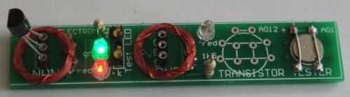
See the project
HERE
TEST EQUIPMENT - the POWER SUPPLY (Make your own)
Everyone and every text book tells you to buy a BENCH POWER SUPPLY.
But I am going to talk from 50 years experience.
If you are designing or repairing a project, you should connect it to a set of weak AA cells to see how it performs. This "Power Supply" will only deliver a small current and if the project has a fault, the voltage will drop considerably and the current will hopefully be small and the current will not damage anything.
This is the way you do your first "Test-Analysis." By monitoring the voltage of the supply you can work out the current requirement. You can also find out if the project works on a reduced voltage.
Once you know the project does not have any short-circuits, you can use a new set of cells and then advance to a rechargeable set of cells or a BENCH POWER SUPPLY.
This method will also let you find a short circuit or a faulty transistor by feeling each component without blowing it up completely.
The only time I have had to use a Bench Power Supply has been for projects that need a variable power supply to show a cascade of LEDs that indicate the supply voltage.
For everything else I use a weak set of cells, a good set of cells and 12v made from Alkaline cells as it will deliver more than 10 amps.
This covers the whole range of requirements at very little cost.
If you want to power a project for a long period of time, you can buy a Wall Wort or Plug Pack for a few dollars on eBay or use a 5v phone charger or put 2 or 3 discarded chargers in series to get 10v or 15v. Put 1,000u electrolytic across each 5v output to help balance the contribution from each charger.
MULTIMETERS
There are two types:
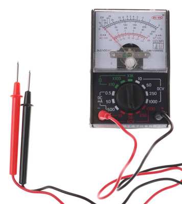
DIGITAL and ANALOGUE
A Digital Multimeter has a set of digits on the display and an Analogue Multimeter has a scale with a pointer (or needle).
You really need both types to cover the number of tests needed for designing and repair-work. We will discuss how they work, how to use them and some of the differences between them.
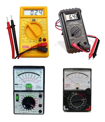
DIGITAL AND ANALOGUE MULTIMETERS
BUYING A MULTIMETER
There are many different types on the market.
The cost is determined by the number of ranges and also the extra features such as diode tester,
buzzer (continuity), transistor tester, high DC current and others.
Since most multimeters are reliable and accurate, buy one with the greatest
number of ranges at the lowest cost.
This article explains the difference between a cheap analogue meter,
an expensive analogue meter and a digital meter. You will then be able
to work out which two meters you should buy.
Multimeters are sometimes called a "meter", a "VOM"
(Volts-Ohms-Milliamps or Volt Ohm Meter) or "multi-tester" or
even "a tester" - they are all the same.
USING A MULTIMETER
Analogue and digital multimeters have either a rotary selector switch or
push buttons to select the appropriate function and range. Some Digital
Multimeters (DMMs) are auto ranging; they automatically select the
correct range of voltage, resistance, or current when doing a test.
However you need to select the function.
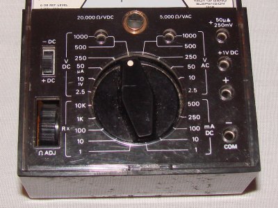
Before making any measurement you need to know what you are
checking. If you are measuring voltage, select the AC range (10v, 50v,
250v, or 1000v) or DC range (0.5v, 2.5v, 10v, 50v, 250v, or 1000v). If
you are measuring resistance, select the Ohms range (x1, x10, x100, x1k,
x10k). If you are measuring current, select the appropriate current range DCmA
0.5mA, 50mA, 500mA. Every multimeter is different however the photo
below
shows a low cost meter with the basic ranges.
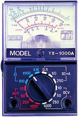
The most important point to remember is this:
You must select a voltage or current range that is bigger or HIGHER than the
maximum expected value, so the needle does not swing across the scale
and hit the "end stop."
If you are using a DMM (Digital Multi Meter), the meter will indicate if
the voltage or current is higher than the selected scale, by showing "OL"
- this means "Overload." If you are measuring resistance such as 1M on
the x10 range the "OL" means "Open Loop" and you will need to change the
range. Some
meters show "1' on the display when the measurement is higher than
the display will indicate and some flash a set of digits to show
over-voltage or over-current. A "-1" indicates the leads should be
reversed for a "positive reading."
If it is an
AUTO RANGING meter, it will automatically produce a reading, otherwise
the selector switch must be changed to another range.
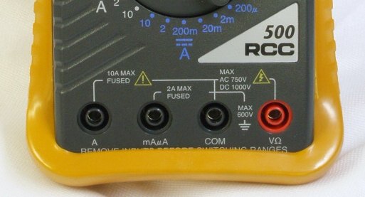
The Common (negative) lead ALWAYS
fits into
the "COM" socket. The red lead fits into the
red socket for Voltage and Resistance.
Place the red lead (red banana plug)
into "A" (for HIGH CURRENT "Amps")
or mA,uA for LOW
CURRENT.
The black "test lead" plugs into the
socket marked "-" "Common",
or "Com," and the red
"test lead" plugs into meter socket marked "+" or
"V-W-mA."
The third banana socket measures HIGH CURRENT and the positive (red lead)
plugs into this. You DO NOT move the negative "-" lead at any
time.
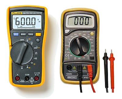
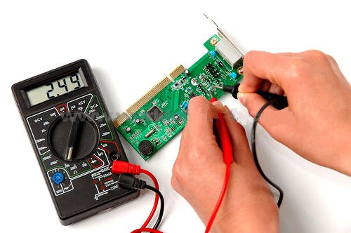
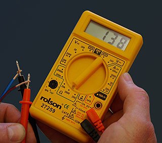
The following two photos show the test leads fitted to a digital meter.
The probes and plugs have "guards" surrounding the probe tips and
also the plugs
so you can measure high voltages without getting near the
voltage-source.
The question above applies to both (every) type of multimeter and the type of meter you use depends on the accuracy you need. Sometimes you are looking for 1mV change on a 20v rail. Only a DMM will (or a CRO) will produce a result.
Analogue meters have an "Ohms Adjustment" to allow for the change in voltage of the battery inside the meter (as it gets old).
"Ohms Adjust" is
also
called "ZERO SET"
The sensitivity of this meter is
20,000ohms/volt
on the DC ranges and 5k/v on the AC ranges
Before taking a resistance reading (each
time, on any of the Ohms scales) you need
to "ZERO SET" the scale, by touching the two probes together and
adjust the pot until the needle reads "0" (swings FULL SCALE).
If the pointer does not reach full scale, the batteries need replacing.
Digital multimeters do not
need "zero adjustment."
Current flows through the
multimeter from the positive probe to the negative probe and the
arrow on the meter above shows this direction. If you cannot remember how to
connect a multimeter when testing CURRENT, tilt it slightly so
the positive terminal is higher than the negative
terminal and lay the red probe on the bench, HIGHER than
the black probe.
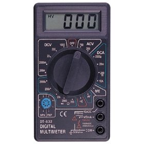
MEASURING FREQUENCY
Before we
cover the normal uses for a multimeter, it is interesting to note that
some Digital Multimeters (DMM) have features such as Capacitance,
Frequency and measuring the gain of a transistor as well as a number of
other features using probes such as a temperature probe. The VICHY
VC99 meter above is an example and costs about $40.00.
Basic function
Range
DCV
600mV/6V/60V/600V/1000V
ACV
6V/60/600/1000V
DCA
600uA/6000uA/60mA/600mA/6A/20A
ACA
600uA/6000uA/60mA/600mA/6A/20A
Resistance
600Ω/6kΩ/60kΩ/600kΩ/6MΩ/60MΩ
Capacitance
40nF/
400nF/4uF/40uF/400uF/2000uF
Frequency
100Hz/1kHz/10kHz/100kHz/1MHz/60MHz
Temperature
-40°C~1000°C
0°F~1832°F
MEASURING VOLTAGE
THE MULTIMETER
I test
all my projects with a $5.00 multimeter !!
WHY???
Because an analogue multimeter puts a load on a circuit and the
reading MUST be genuine.
Secondly, an analogue multimeter will show fluctuations in a
circuit and show when a certain part of a circuit is not
maintaining stability.
And thirdly, an analogue multimeter will respond to changes and
pulses much faster than a digital meter.
Lastly, if I can design and test a circuit with a cheap meter,
everyone else should be able to do the same when using a
more-expensive meter.
Finally, an analogue meter lasts a lifetime. But if you damage
it, the cost is only $5.00
And you get 500mA range, a digital meter gives 200mA.
Analogue Meters are on
eBay
I have digital meter when I want to read voltages accurately.
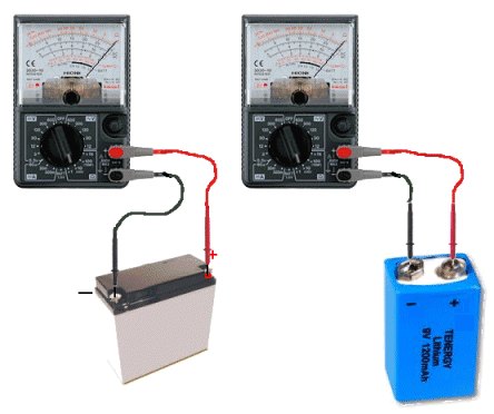
If you buy two multimeters, you can test currents
up to 1 amp by placing the multimeters in PARALLEL as shown in
the following diagram:
The red and black probes go to the positive and
negative terminals of the project you are testing and you simply
ADD the current readings (shown by the pointer on each
meter) to get a final value (up to one amp).
This is how we arrive at that statement:
When taking a measurement of CURRENT, the voltage on the
positive probe will be very slightly higher than the
voltage on the negative probe, because a very small voltage will
be dropped across the CURRENT RESISTOR inside the meter. The
meter is actually measuring the voltage across this resistor and
you are reading the pointer where the scale says 0-500mA.
We know that current flows from positive to negative and when
you trace the circuit above, you can see the meter is part of
this circuit.
When measuring CURRENT, you use exactly the same reasoning as
when you are measuring voltage.
Look at the circuit or project and work out which point will
have the (slightly) higher voltage. The red probe goes to this
point.
When measuring CURRENT, even the wires will have a slightly
higher voltage at one end. This is the end for the red probe.
When measuring CURRENT, the circuit has to be CUT and the probes
inserted into the CUT. You cannot measure the current taken by
a component by placing the probes "across it." You have to cut a
wire or a track or desolder one of the wires.
Now connect the red probe to the positive terminal of the
battery and the black probe to the positive "input" of the
project. Use another jumper to connect the negative of the
battery to the negative (0v) of the project.
See how the current has to flow across the meter (from left to
right) to make the point read "up-scale". The probes are
connected to the battery as shown in the diagram above.
FIXING A MULTIMETER
A multimeter can get "broken"
"damaged" and go "faulty."
I don't know why, but eventually they stop working.
It can be something simple like a flat battery, corroded battery
contacts, broken switch or something complex, like the circuitry
failing.
Multimeters are so cheap, you can buy a new one for less than $10.00
These meters can have a 10 amp range, transistor tester and measure up
to 2 meg ohms.
That's why I suggest buying a $10.00 meter. They are just as good
as a $60.00 meter and the cheapest meters last the longest.
Dropping an analogue meter can cause the hair spring to loop over one of
the supports and the needle will not zero correctly. You will need to
open the cover on the movement and lift the spring off the support with
a needle.
A faulty meter can be used in a battery-charger circuit to measure the
current or voltage if that scale is still reading-correctly.
Otherwise keep the leads and throw the meter out. It is too dangerous
keeping a meter that shows an incorrect reading.
NOTE: When the battery in a digital meter gets low, the digits on
the display start to fade and you need to change the 12v battery.
But before this happens, the low battery voltage will make a voltage
reading higher than the actual value and this can fool you.
This happened to me. The 5v regulator voltage increased to 6v, 7v, 8v and
I thought the regulator had failed. Then the display failed and
changing the battery solved the problem.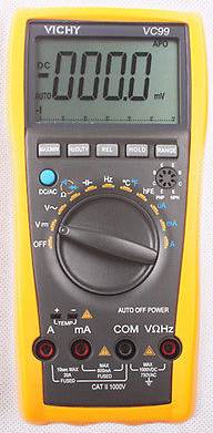
Most of the readings you will take with a multimeter will be VOLTAGE readings.
Before taking a reading, you should select the highest range and if the
needle does not move up scale (to the right), you can select another
range.
Always switch to the highest range before probing a circuit and keep
your fingers away from the component being tested.
If the meter is Digital, select the highest range or use the
auto-ranging feature, by selecting "V."
The meter will automatically produce a result, even if the voltage is AC
or DC.
If the meter is not auto-ranging, you will have to select
![]() if the
voltage is from a DC source or
if the
voltage is from a DC source or
![]() if the
voltage is from an AC source. DC means Direct Current and the voltage is
coming from a battery or supply where the voltage is steady and not
changing and AC means Alternating Current where the voltage is coming
from a voltage that is rising and falling.
if the
voltage is from an AC source. DC means Direct Current and the voltage is
coming from a battery or supply where the voltage is steady and not
changing and AC means Alternating Current where the voltage is coming
from a voltage that is rising and falling.
You can measure the voltage at different points in a circuit by
connecting the black probe to chassis. This is the 0v reference and is
commonly called "Chassis" or "Earth" or "Ground" or "0v."
The red lead is called the "measuring lead" or "measuring probe"
and it can measure voltages at any point in a circuit. Sometimes there
are "test points" on a circuit and these are wires or loops designed to hold the tip
of the red probe (or a red probe fitted with a mini clip or mini
alligator clip).
You can also measure voltages ACROSS A COMPONENT. In other words,
the reading is taken in PARALLEL with the component. It may be the voltage across
a transistor, resistor, capacitor, diode or coil. In most cases this
voltage will be less than the supply voltage.
If you are measuring the voltage in a circuit that has a HIGH IMPEDANCE,
the reading will be inaccurate, up to 90% !!!, if you use a cheap
analogue meter.
Here's a simple case.
The circuit below consists of two 1M resistors in series. The voltage at the mid point will be 5v when nothing is connected to the mid point. But if we use a
cheap analogue multimeter set to 10v, the resistance of the meter
will be about 100k, if the meter has a sensitivity of 10k/v and the reading will be incorrect.
Here how it works:
Every meter has a sensitivity. The sensitivity of the meter is the
sensitivity of
the movement and is the amount of current required to deflect the
needle FULL SCALE.
This current is very small, normally 1/10th of a milliamp and
corresponds to a sensitivity of 10k/volt (or 1/30th mA, for a sensitivity of 30k/v).
If an analogue meter is set to 10v, the internal resistance of the meter
will be 100k for a 10k/v movement.
If this multimeter is used to test the following circuit, the reading
will be inaccurate.
The reading should be 5v as show in diagram
A.
But the analogue multimeter has an internal resistance of 100k and it
creates a circuit shown in
C.
The top 1M and 100k from the meter create a combined PARALLEL resistance
of 90k. This forms a series circuit with the lower 1M and the meter
will read less than 1v
If we measure the voltage across the lower 1M, the 100k meter will form
a value of resistance with the lower 1M and it will read less than 1v
If the multimeter is 30k/v, the readings will be 2v.
See how easy it is to get a totally inaccurate reading.
This introduces two new terms:
HIGH IMPEDANCE CIRCUIT and "RESISTORS in SERIES and
PARALLEL."
If the reading is taken with a Digital Meter, it will be more accurate
as a DMM does not take any current from the circuit (to activate the
meter). In other words it has a very HIGH input impedance. Most Digital
Multimeters have a fixed input resistance (impedance) of 10M - no matter
what scale is selected.
That's the reason for choosing a DMM for high impedance circuits.
It also gives a reading that is accurate to about 1%.
MEASURING VOLTAGES
IN A CIRCUIT
You can take many
voltage-measurements in a circuit. You can measure "across" a component,
or between any point in a circuit and either the positive rail or earth
rail (0v rail). In the following circuit, the 5 most important
voltage-measurements are shown. Voltage "A" is across the electret
microphone. It should be between 20mV and 500mV. Voltage "B" should be
about 0.6v. Voltage "C" should be about half-rail voltage. This allows
the transistor to amplify both the positive and negative parts of the
waveform. Voltage "D" should be about 1-3v. Voltage "E" should be the
battery voltage of 12v.
MEASURING VOLTAGES IN A CIRCUIT
MEASURING CURRENT
You will rarely need to take
current measurements, however most multimeters have DC current ranges
such as 0.5mA, 50mA, 500mA and 10Amp (via the extra banana socket)
and some meters have AC current ranges. Measuring the current of a circuit will tell you a lot of things.
If you know the normal current, a high or low current can let you know if
the circuit is overloaded or not fully operational.
Current is always measured when the circuit is working (i.e: with power applied).
It is measured IN SERIES with the
circuit or component under test.
The easiest way to measure current is to remove the fuse and take a
reading across the fuse-holder. Or remove one lead of the battery or turn the
project off, and measure across the switch.
If this is not possible, you will need to remove one end of a component
and measure with the two probes in the "opening."
Resistors are the easiest things to desolder, but you may have to cut a
track in some circuits. You have to get an "opening" so that a current
reading can be taken.
The following diagrams show how to connect the probes to take a CURRENT
reading.
Do not measure the current ACROSS a component as this will create a
"short-circuit."
The component is designed to drop a certain voltage and when you place
the probes across this component, you are effectively adding a "link" or
"jumper" and the voltage at the left-side of the component will appear
on the right-side. This voltage may be too high for the circuit being
supplied and the result will be damage. 
Measuring current through a resistor
Measuring the current of a globe
Do NOT measure the
CURRENT of a battery
A battery will deliver a very HIGH current
and damage the meter
Do not measure the "current a battery will deliver" by placing the probes
across the terminals. It will deliver a very high current and damage the
meter instantly. There are special battery testing instruments for this
purpose.
When measuring across an "opening" or "cut," place the red probe on the
wire that supplies the voltage (and current) and the black probe on the
other wire. This will produce a "POSITIVE" reading.
A positive reading is an UPSCALE READING and the pointer will move
across the scale - to the right. A "NEGATIVE READING" will make the pointer hit the
"STOP"
at the left of the scale and you will not get a reading. If you are
using a Digital Meter, a negative sign "-" will appear on the screen to
indicate the probes are around the wrong way. No damage will be caused.
It just indicates the probes are connected incorrectly.
If you want an accurate CURRENT MEASUREMENT, use a digital meter.
MEASURING 1 AMP
Most digital multimeters only go to 200mA and most cheap analogue meters
only go to 500mA.
But a clever way to measure up to 1 amp is to put 2 cheap analogue
meters in parallel and read the two screens. Just add the combined
values and you will be able to read up to 1 amp.
Just another time when a cheap $5.00 analogue meter comes in handy.
Here is anther way to increase the current range:
I have converted one of the meters above to 0-5AMP
using 8 x 1 ohm 0.25watt resistors in parallel on the 100mA range and
the reading is 0 - 5 amp on the 50v scale.
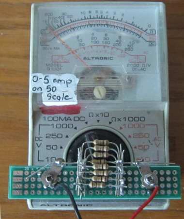
Turning an old meter into a valuable 0-5Amp meter
This is how you do it.
Get an old meter for conversion.
Get a good meter with a 0-200mA or 0-500mA scale.
Get a 12v supply and 3 or 5 watt wire wound resistors 8R2 and 3R3 etc.
As many as you can.
Make a resistive circuit that draws say 100mA and check the current with
the good meter (separately) and then with the meter you are going to
modify to make sure both meters are detecting the correct amount of
current.
Now you have a starting-point.
Make the SHUNT - the resistors soldered in parallel on the matrix board
above - using 8 x one ohm resistors.
Connect the two meters in series with (wire wound resistors) to the 12v
supply until the good meter (called the calibrating meter) reads FULL
DEFLECTION.
If you add another resistor, the needle reading will go DOWN SCALE. If
you remove a resistor the needle will move UP-SCALE.
Now adjust the number of resistors until the meter you are calibrating
reads the same current.
This is as far as you can go.
You don't need any complex mathematics. Just a simple addition or
removal of resistors. You can use 2R2 or 3R3 to make smaller increments
or decrements in the position of the pointer.
This is not the best way to calibrate a meter but it is is the best we
can do. Any inaccuracy in our calibration will be multiplied 5 times in
the final reading - but this is a simple way to turn an old meter into
something valuable.
Now remove the calibrating meter and reduce the number of wire wound
resistors and the needle will move UP-SCALE. Reduce the number of wire
wound resistors and the remaining resistors will get HOT and the needle
will move up scale to the 5 amp reading.
You now have a valuable 0-5 amp CURRENT METER.
Called an AMMETER (0-5AMP)
Called a 5-Amp Meter or
5-Amp AMMETER (this is the best name).
Here is another way to convert a digital meter:
Most digital meters only read to to 200mA. You can increase this to 1
amp with the following simple set of resistors called SHUNT RESISTORS.
Place the multimeter in series with a load that is taking 200mA.
Now get some one ohm, 2.2ohm and 3.3 ohm resistors. Place them, one at a
time, across the two probes and you will find the reading will reduce
every time you add a resistor.
You can put them directly across the probes or two in series to get a
larger résistance.
Keep experimenting until the reading on the meter is "40." You
know this reading is really 200mA, so, when the probes are put on a
circuit that reads "200" the real current will be 200 x 5 =
1,000mA or 1AMP!
MEASURING AC CURRENT
Measuring AC current is very difficult to do because the
waveform is rising and falling and when the waveform is "on and off"
such as the DCC waveform in a DCC Model Railway set-up, the actual
current taken by a module will be impossible to measure with a cheap
multimeter.
However a simple way to find out the current flowing is to place a 500
ohm pot in the positive line and connect a LED from the middle pin to
one of the outer pins and then connect another LED across the LED but in
the opposite direction. This will only be suitable for a current up to
about 50mA.
As you turn the pot from zero ohms, the LEDs will start to come on.
We are NOT measuring the brightness but the point at which the LED
detects a voltage of about 3.2v across the pot. (actually across about
half the pot)
Now put the "tester" on a variable power supply and connect a 220R as
the load. As you increase the voltage, one of the LEDs will come on with
the same very weak brightness. Now place a DC milliamp meter in line
with the tester and measure the current. The value will be very close to
the AC current flowing in the original circuit.
The same principle can be used to measure higher currents by using a
low-resistance resistor and 2 LEDs.
Suppose you have a 10 ohm resistor and LEDs that illuminate at 3.2v
When the current peaks at 320mA, the LEDs will be illuminated with very
low brightness, but because the peak will only be for a very small
portion of the cycle, the actual current-flow will not be equal or the
same as 320mA DC current. We are just measuring a PEAK.
You have to be careful when making this type of "tester" to prevent
damaging the LEDs. Start with a set of say 5 resistors in parallel with
each value 47 ohms or slightly higher or lower. As you remove each
resistor, the LEDs will start to come ON.
This will let you know that some point in the cycle the current is
320mA.
If it is a square-wave, such as the DCC waveform for Model Railways, the
DC current-flow will be very nearly the same as the AC current measured
by this tester.
CURRENT SHARING
This is a term we use when two or more devices are placed in parallel
and we hope each device will dissipate half the heat.
Suppose you have a component that gets too hot. You can add a heatsink
or place another component "across it."
The first thing you have to remember is this: a lot of the heat from the
component goes down the leads and into the tracks on the printed circuit
board.
If you add another component you are sending the heat from two devices
to the same tracks. You may need to keep the two devices apart.
However if the device is a transistor or diode the original device will
drop a higher voltage when the full current flows and that's why it is
getting so hot.
If you add another device on top of it, each device will pass less
current and the voltage-drop across the combination will be less and the
overall heat loss will be less.
So you will be solving 3 problems at the same time.
1. The voltage-drop across the combination will be less,
2. The heat will be distributed via more devices, and
3. The set-up will fail less often because it is not being driven so
hard.
A 1-amp diode can be connected across a 2-amp diode to reduce the
heating of each component and the effectiveness needs to be tested with
your fingers.
There is no law or rule for this but a silicon diode drops about 0.7v
when half the specified current is flowing and rise to 1.1v when full
current flows. Buy adding another diode across the first, the overall
characteristic voltage drop across the combination can reduced
considerably.
The same concept of current sharing applies to resistors and they can be
placed in parallel or series to distribute the heat, but make sure the
tracks on the board can dissipate the heat.
The rating of a resistor ONLY applies when it is connected close to the
PC board and when the tracks are thick enough to dissipates the heat.
Resistors "up in the air" can dissipate very little.
The same concept of current sharing can also be used for 3-terminal
regulators and to find if they are equal-sharing, place your fingers on
both at the same time and see if you let-go at the same time.
The same concept of current sharing can be used for zener diodes, as the
current-capability of a high-voltage zener is less than a low voltage
zener. So, two zeners, 6v2 and 6v2 can be used for a 12v supply
and the current capability of the set-up will be 64mA whereas a 12v
zener of the same 400mW rating will be 33mA. Sometimes you need the
zener to dissipate all the wattage when a LOAD is not connected to the
circuit. This is the concept of a zener diode as a SHUNT
REGULATOR. See:
Zener Diode - about halfway down the
article we describe a SHUNT REGULATOR.
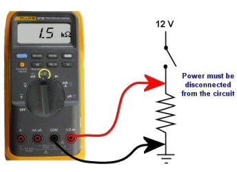
Turn a circuit off before measuring resistance.
If any voltage is present, the value of resistance will be incorrect.
In most cases you cannot measure a component while it is in-circuit. This is because the meter is actually measuring a voltage across a component and calling it a "resistance." The voltage comes from the battery inside the meter. If any other voltage is present, the meter will produce a false reading.
If you are measuring the resistance of a component while still "in circuit," (with the power off) the reading will be lower than the true reading.
Measuring resistance
Measuring resistance of a heater
(via the leads)
Measuring the resistance of a
piece of resistance-wire
Measuring the resistance of a
resistor
Do not measure the "Resistance of
a Battery"
1. Do not measure the "resistance of a battery." The resistance of a
battery (called the Internal impedance) is not measured as shown in the
diagrams above. It is measured by creating a current-flow and measuring
the voltage across the battery. Placing a multimeter set to resistance (across a battery) will destroy the meter.
2. Do not try to measure the resistance of any voltage or any "supply."
Resistance is measured in OHMs.
The resistance of a 1cm x 1cm bar, one metre long is 1 ohm.
If the bar is thinner, the resistance is higher. If the bar is longer,
the resistance is higher.
If the material of the bar is changed, the resistance is higher.
When carbon is mixed with other elements, its resistance increases and
this knowledge is used to make RESISTORS. (However, when carbon is mixed
with non-conducting powders, the resistance decreases. Such as mixing
carbon with depolariser chemicals in a "dry cell.")
Resistors have RESISTANCE and the main purpose of a resistor is to
reduce the CURRENT FLOW.
It's a bit like standing on a hose. The flow reduces.
When current flow is reduced, the output voltage is also reduced and
that why the water does not spray up so high. Resistors are simple
devices but they produce many different effects in a circuit.
A resistor of nearly pure carbon may be 1 ohm, but when non-conducting
"impurities" are added, the same-size resistor may be 100 ohms, 1,000
ohms or 1 million ohms.
Circuits use values of less than 1 ohm to more than 22 million ohms.
Resistors are identified on a circuit with numbers
and letters to show the exact value of resistance - such as 1k
2k2 4M7
The letter
W (omega - a Greek symbol)
is used to identify the word "Ohm."
but this symbol is not available on some word-processors, so the
letter "R" is used. The letter "E" is also sometimes used and both
mean "Ohms."
A one-ohm resistor is written "1R" or "1E." It can also be written
"1R0" or "1E0."
A resistor of one-tenth of an ohm is written "0R1" or "0E1."
The letter takes the place of the decimal point.
10 ohms = 10R
100 ohms = 100R
1,000 ohms = 1k (k= kilo = one thousand)
10,000 ohms = 10k
100,000 ohms = 100k
1,000,000 ohms = 1M (M = MEG = one million)
The size of a resistor has nothing to do with its resistance. The size
determines the wattage of the resistor - how much heat it can dissipate
without getting too hot.
Every resistor is identified by colour bands on the body, but when the
resistor is a surface-mount device, numbers are used and sometimes
letters.
You MUST learn the colour code for resistors and the following table
shows all the colours for the most common resistors from 1/10th of an
ohm to 22 Meg ohms for resistors with 5% and 10% tolerance.
If
3rd band is gold, Divide by 10
If 3rd band is silver, Divide by 100
(to get 0.22ohms etc)

Reading 4-band
resistors
The most "common" type of
resistor has 4 bands and is called the 10% resistor. It now has a
tolerance of 5% but is still called the "10% type" as the colours
increase by 20% so that a resistor can be 10% higher or 10% lower than a
particular value and all the resistors produced in a batch can be
used.
The first 3 bands produce the resistance and the fourth band is the
"tolerance" band. Gold = 5%
(Silver =10% but no modern resistors are 10%!! - they are
5% 2% or 1%)
 |
 |
 |
 |
 |
 |
 |
 |
Download the program and save it on your desk-top for future
reference:
ColourCode.exe (520KB)
ColourCode.zip (230KB)
ColourCode.rar (180KB)
When the third band is gold, it indicates the value of the "colors" must be divided by 10.
Gold = "divide by 10" to get values 1R0 to 8R2
When the third band is silver, it indicates the value of the "colors" must be divided by 100. (Remember: more letters in the word "silver" thus the divisor is "a larger division.")
Silver = "divide by 100" to get values R1 to R82
e.g: 0R1 = 0.1 ohm 0R22 = point 22 ohms
See 4th Column above for examples.
The letters "R, k and M" take the place of a decimal point.
e.g: 1R0 = 1 ohm 2R2 = 2 point 2 ohms 22R = 22 ohms
2k2 = 2,200 ohms 100k = 100,000 ohms
2M2 = 2,200,000 ohms
HOW TO REMEMBER THE COLOUR CODE:
Each colour has a "number" (or divisor) corresponding to it.
Most of the colours are in the same order as in the spectrum. You can see the spectrum in a rainbow. It is: ROY G BIV and the colours for resistors are in the same sequence.
black
brown - colour of increasing temperature
red
orange
yellow
green
blue
(indigo - that part of the spectrum between blue and violet)
violet
gray
white
| colour | value | No of zero's |
| silver | -2 | divide by 100 |
| gold | -1 | divide by 10 |
| black | 0 | No zeros |
| brown | 1 | 0 |
| red | 2 | 00 |
| orange | 3 | ,000 or k |
| yellow | 4 | 0,000 |
| green | 5 | 00,000 |
| blue | 6 | M |
| violet | 7 | |
| gray | 8 | |
| white | 9 |

Here are some common ways to remember the
colour code:
Bad Beer Rots Our Young Guts, But Vodka Goes Well
Bright Boys Rave Over Young Girls But Violet Gets Wed
Bad Boys Rave Over Young Girls But Violet Gets Wed with Gold and
Silver.
Reading 5-band resistors:
5-band resistors are easy to read if you remember two simple points. The first three bands provide the digits in the answer and the 4th band supplies the number of zero's.
Reading
"STANDARD VALUES" (on
5-band resistors)
The first two colour-bands for a STANDARD VALUE or "common value" in 1% or 5% will be the SAME. These two bands provide the digits in the answer.
It's the 3rd band for a 5% resistor that is expanded into two bands in a 1% resistor. But it's easy to follow.
For a standard value, the 3rd band in a 1% resistor is BLACK. This represents a ZERO in the answer. (For 5-band resistors BLACK represents a ZERO when in the third band. This is different to 4-band resistors where black represents the word OHMS! If the third band is BROWN, the answer will be 1).
So the 4th band has to represent one-less ZERO and is one colour UP THE COLOUR CHART! In other words the 3rd and 4th bands (combined) on a 1% resistor produces the same number of zero's as the 3rd band on a 5% resistor!
Resistors come in a range of values and the two most common are the E12 and E24 series. The E12 series comes in twelve values for each decade. The E24 series comes in twenty-four values per decade.
E12 series - 10, 12, 15, 18, 22, 27, 33, 39, 47, 56, 68, 82
E24 series - 10, 11, 12, 13, 15, 16, 18, 20, 22, 24, 27, 30, 33, 36, 39, 43, 47, 51, 56, 62, 68, 75, 82, 91
Here is the complete list of
1% 1/4watt resistors from:
CIRCUIT SPECIALISTS.
The following list covers 10 ohms (10R) to 1M.
To buy 1% resistors from Circuit Specialists, click:
HERE.
| 10R 12R1 15R 18R2 22R1 27R4 30R1 33R2 36R5 39R2 47R5 49R9 51R1 56R2 68R1 75R 82R5 90R9 100R |
121R 150R 182R 200R 221R 240R 249R 274R 301R 332R 348R 392R 402R 475R 499R 565R 604R 681R 750R |
806R 825R 909R 1k0 1k21 1k5 1k82 2k 2k21 2k2 2k43 2k49 2k67 2k74 3k01 3k32 3k48 3k57 3k74 |
3k83 3k92 4k02 4k22 4k64 4k75 4k7 4k87 4k99 5k11 5k23 5k36 5k49 5k62 5k76 5k9 6k04 6k19 6k81 |
7k15 7k5 7k87 71k5 8k06 8k25 8k45 8k66 8k87 9k09 9k31 9k53 9k76 10k 11k 12k 12k1 12k4 13k |
14k7 15k 15k8 16k9 17k4 17k8 18k2 20k 22k1 22k6 23k7 24k9 27k4 29k4 30k1 33k2 34k8 36k5 38k3 |
39k2 40k2 44k2 46k4 47k 47k5 49k9 51k1 53k6 56k2 61k9 68k1 69k8 75k0 82k5 90k 90k9 95k3 100k |
121k 147k 150k 182k 200k 212k 221k 226k 249k 274k 301k 332k 357k 392k 475k 487k 499k 562k 604k 1M |
Here is the list of 1% resistors from suppliers (such as Farnell):
| 1R0 1R2 1R5 2R2 2R7 3R3 3R9 4R7 5R6 6R2 6R8 7R5 8R2 9R1 10R 11R 12R |
13R 15R 16R 18R 20R 22R 24R 27R 30R 33R 36R 39R 43R 47R 51R 56R 62R |
68R 75R 82R 91R 100R 110R 120R 130R 150R 160R 180R 200R 220R 240R 270R 300R 330R |
360R 390R 430R 470R 510R 560R 620R 680R 750R 820R 910R 1k 1k1 1k2 1k3 1k5 1k6 |
1k8 2k0 2k2 2k4 2k7 3k 3k3 3k6 3k9 4k3 4k7 5k1 5k6 6k2 6k8 7k5 8k2 |
9k1 10k 11k 12k 13k 15k 16k 18k 20k 22k 24k 27k 30k 33k 36k 39k 43k |
47k 51k 56k 62k 68k 75k 82k 91k 100k 110k 120k 130k 150k 160k 180k 200k 220k |
240k 270k 300k 330k 360k 390k 430k 470k 510k 560k 620k 680k 750k 820k 910k 1M |
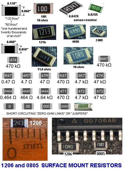
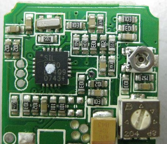
3-digit Surface Mount resistors on a PC board
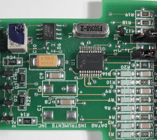
4-digit Surface Mount resistors on a PC board
The photo above shows
surface mount resistors on a circuit board. The components that are not
marked are capacitors (capacitors are NEVER marked).
All the SM resistors in the above photos conform
to a 3-digit or 4-digit code. But there are a number of codes, and the 4-digit
code caters for high tolerance resistors, so it's getting very complicated.
Here is a basic 3-digit SM resistor:
A 330k SM resistor
The first two digits represent the two
digits in the answer. The third digit represents the number of zero's
you must place after the two digits. The answer will be OHMS. For
example: 334 is written 33 0 000. This is written 330,000 ohms. The
comma can be replaced by the letter "k". The final answer is: 330k.
222 = 22 00 = 2,200 = 2k2
473 = 47 000 = 47,000 = 47k
474 = 47 0000 = 470,000 = 470k
105 = 10 00000 = 1,000,000 = 1M = one million ohms
There is one trick you have to remember. Resistances less than 100 ohms
are written: 100, 220, 470. These are 10 and NO zero's = 10 ohms = 10R
or 22 and no zero's = 22R or 47 and no zero's = 47R. Sometimes the
resistor is marked: 10, 22 and 47 to prevent a mistake.
Remember:
R = ohms
k = kilo ohms = 1,000 ohms
M = Meg = 1,000,000 ohms
The 3 letters (R, k and M) are put in place of the decimal point. This
way you cannot make a mistake when reading a value of resistance.
Surface Mount
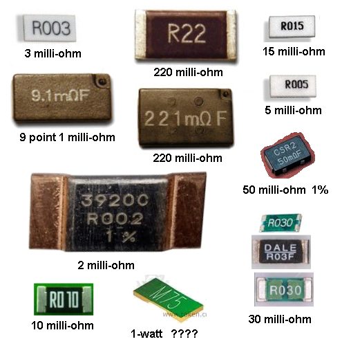
CURRENT SENSING Resistors
Many new types of CURRENT
SENSING surface-mount resistors are appearing on the market and these
are creating lots of new problems.
Fortunately all resistors are marked with the value of resistance and
these resistors are identified in MILLIOHMS. A miili ohm is one
thousandth or an ohm and is written 0.001 when writing a normal
mathematical number.
When written on a surface mount resistor, the letter R indicates the
decimal point and it also signifies the word "OHM" or "OHMS" and one
milli-ohm is written R001
Five miiliohms is R005 and one hundred milliohms is R100
Some surface mount resistors have the letter "M" after the value to
indicate the resistor has a rating of 1 watt. e.g: R100M
These surface-mount resistors are specially-made to withstand a high
temperature and a surface-mount resistor of the same size is normally
250mW or less.
These current-sensing resistors can get extremely hot and the PC board
can become burnt or damaged.
When designing a PC board, make the lands very large to dissipate the
heat.
Normally a current sensing resistor is below one ohm (1R0) and it is
easy to identify them as R100 etc.
You cannot measure the value of a current sensing resistor as the leads
of a multimeter have a higher resistance than the resistor and few
multimeters can read values below one ohm.
If the value is not visible, you will have to refer to the circuit.
Before replacing it, work out why it failed.
Generally it gets too hot. Use a larger size and add tiny heatsinks on
each end.
Here are some surface=mount current-sense resistors:
THE COMPLETE RANGE OF SM
RESISTOR
MARKINGS
Click to see the complete range of SM resistor markings for 3-digit
code:
Click to see the complete range of SM resistor markings for 4-digit code:
0000 is a value on a surface-mount resistor. It is a zero-ohm LINK!
Resistances less than 10 ohms have 'R' to indicate the position of the decimal point.
Here are some examples:
|
Three Digit Examples
|
Four Digit Examples
|
| 330 is 33 ohms - not 330 ohms |
1000
is 100 ohms -
not 1000 ohms
|
| 221 is 220 ohms |
4992 is
49 900 ohms, or 49k9
|
| 683 is 68 000 ohms, or 68k |
1623
is 162 000 ohms, or 162k
|
| 105 is 1 000 000 ohms, or 1M |
0R56
or R56 is
0.56 ohms |
| 8R2 is 8.2 ohms |
A new coding system has appeared on 1% types. This is known as the EIA-96 marking method. It consists of a three-character code. The first two digits signify the 3 significant digits of the resistor value, using the lookup table below. The third character - a letter - signifies the multiplier.
|
code
|
value
|
code
|
value
|
code
|
value
|
code
|
value
|
code
|
value
|
code
|
value
|
|||||
|
01
|
100
|
17
|
147
|
33
|
215
|
49
|
316
|
65
|
464
|
81
|
681
|
|||||
|
02
|
102
|
18
|
150
|
34
|
221
|
50
|
324
|
66
|
475
|
82
|
698
|
|||||
|
03
|
105
|
19
|
154
|
35
|
226
|
51
|
332
|
67
|
487
|
83
|
715
|
|||||
|
04
|
107
|
20
|
158
|
36
|
232
|
52
|
340
|
68
|
499
|
84
|
732
|
|||||
|
05
|
110
|
21
|
162
|
37
|
237
|
53
|
348
|
69
|
511
|
85
|
750
|
|||||
|
06
|
113
|
22
|
165
|
38
|
243
|
54
|
357
|
70
|
523
|
86
|
768
|
|||||
|
07
|
115
|
23
|
169
|
39
|
249
|
55
|
365
|
71
|
536
|
87
|
787
|
|||||
|
08
|
118
|
24
|
174
|
40
|
255
|
56
|
374
|
72
|
549
|
88
|
806
|
|||||
|
09
|
121
|
25
|
178
|
41
|
261
|
57
|
383
|
73
|
562
|
89
|
825
|
|||||
|
10
|
124
|
26
|
182
|
42
|
267
|
58
|
392
|
74
|
576
|
90
|
845
|
|||||
|
11
|
127
|
27
|
187
|
43
|
274
|
59
|
402
|
75
|
590
|
91
|
866
|
|||||
|
12
|
130
|
28
|
191
|
44
|
280
|
60
|
412
|
76
|
604
|
92
|
887
|
|||||
|
13
|
133
|
29
|
196
|
45
|
287
|
61
|
422
|
77
|
619
|
93
|
909
|
|||||
|
14
|
137
|
30
|
200
|
46
|
294
|
62
|
432
|
78
|
634
|
94
|
931
|
|||||
|
15
|
140
|
31
|
205
|
47
|
301
|
63
|
442
|
79
|
649
|
95
|
953
|
|||||
|
16
|
143
|
32
|
210
|
48
|
309
|
64
|
453
|
80
|
665
|
96
|
976
|
The multiplier letters are as follows:
|
letter
|
mult
|
letter
|
mult
|
|
|
F
|
100000
|
B
|
10
|
|
|
E
|
10000
|
A
|
1
|
|
|
D
|
1000
|
X or S
|
0.1
|
|
|
C
|
100
|
Y or R
|
0.01
|
22A is a 165 ohm resistor, 68C is a 49900 ohm (49k9) and 43E a 2740000 (2M74). This marking scheme applies to 1% resistors only.
A similar arrangement can be used for 2% and 5% tolerance types. The multiplier letters are identical to 1% ones, but occur before the number code and the following code is used:
| 2% | 5% | |||||||||
| code |
value
|
code | value |
code
|
value
|
code | value | |||
| 01 |
100
|
13 |
330
|
25
|
100
|
37
|
330
|
|||
| 02 |
110
|
14 |
360
|
26
|
110
|
38
|
360
|
|||
| 03 |
120
|
15 |
390
|
27
|
120
|
39
|
390
|
|||
| 04 |
130
|
16 |
430
|
28
|
130
|
40
|
430
|
|||
| 05 |
150
|
17 |
470
|
29
|
150
|
41
|
470
|
|||
| 06 |
160
|
18 |
510
|
30
|
160
|
42
|
510
|
|||
| 07 |
180
|
19 |
560
|
31
|
180
|
43
|
560
|
|||
| 08 |
200
|
20 |
620
|
32
|
200
|
44
|
620
|
|||
| 09 |
220
|
21 |
680
|
33
|
220
|
45
|
680
|
|||
| 10 |
240
|
22 |
750
|
34
|
240
|
46
|
750
|
|||
| 11 |
270
|
23 |
820
|
35
|
270
|
47
|
820
|
|||
| 12 |
300
|
24 |
910
|
36
|
300
|
48
|
910
|
|||
With this
arrangement, C31 is 5%, 18000 ohm (18k), and D18 is 510000
ohms (510k) 2% tolerance.
Always check with an ohm-meter (a multimeter) to make sure.
Chip resistors come in the
following styles and ratings:
Style: 0402, 0603,
0805, 1206, 1210, 2010, 2512, 3616, 4022
Power Rating:
0402(1/16W), 0603(1/10W), 0805(1/8W), 1206(1/4W), 1210(1/3W),
2010(3/4W), 2512(1W), 3616(2W), 4022(3W)
Tolerance: 0.1%, 0.5%,
1%, 5%
Temperature Coefficient:
25ppm 50ppm 100ppm
|
EIA marking code for surface mount (SMD) resistors |
|||||||
| 01S
= 1R 02S = 1R02 03S = 1R05 04S = 1R07 05S = 1R1 06S = 1R13 07S = 1R15 08S = 1R18 09S = 1R21 10S = 1R24 11S = 1R27 12S = 1R3 13S = 1R33 14S = 1R37 15S = 1R4 16S = 1R43 17S = 1R47 18S = 1R5 19S = 1R54 20S = 1R58 21S = 1R62 22S = 1R65 23S = 1R69 24S = 1R74 25S = 1R78 26S = 1R82 27S = 1R87 28S = 1R91 29S = 1R96 30S = 2R0 31S = 2R05 32S = 2R10 33S = 2R15 34S = 2R21 35S = 2R26 36S = 2R32 37S = 2R37 38S = 2R43 39S = 2R49 40S = 2R55 41S = 2R61 42S = 2R67 43S = 2R74 44S = 2R80 45S = 2R87 46S = 2R94 47S = 3R01 48S = 3R09 49S = 3R16 50S = 3R24 51S = 3R32 52S = 3R4 53S = 3R48 54S = 3R57 55S = 3R65 56S = 3R74 57S = 3R83 58S = 3R92 59S = 4R02 60S = 4R12 61S = 4R22 62S = 4R32 63S = 4R42 64S = 4R53 65S = 4R64 66S = 4R75 67S = 4R87 68S = 4R99 69S = 5R11 70S = 5R23 71S = 5R36 72S = 5R49 73S = 5R62 74S = 5R76 75S = 5R9 76S = 6R04 77S = 6R19 78S = 6R34 79S = 6R49 80S = 6R65 81S = 6R81 82S = 6R98 83S = 7R15 84S = 7R32 85S = 7R5 86S = 7R68 87S = 7R87 88S = 8R06 89S = 8R25 90S = 8R45 91S = 8R66 92S = 8R87 93S = 9R09 94S = 9R31 95S = 9R53 96S = 9R76 |
01R
= 10R 02R = 10R2 03R = 10R5 04R = 10R7 05R = 11R 06R = 11R3 07R = 11R5 08R = 11R8 09R = 12R1 10R = 12R4 11R = 12R7 12R = 13R 13R = 13R3 14R = 13R7 15R = 14R 16R = 14R3 17R = 14R7 18R = 15R 19R = 15R4 20R = 15R8 21R = 16R2 22R = 16R5 23R = 16R9 24R = 17R4 25R = 17R8 26R = 18R2 27R = 18R7 28R = 19R1 29R = 19R6 30R = 20R0 31R = 20R5 32R = 21R0 33R = 21R5 34R = 22R1 35R = 22R6 36R = 23R2 37R = 23R7 38R = 24R3 39R = 24R9 40R = 25R5 41R = 26R1 42R = 26R7 43R = 27R4 44R = 28R0 45R = 28R7 46R = 29R4 47R = 30R1 48R = 30R9 49R = 31R6 50R = 32R4 51R = 33R2 52R = 34R0 53R = 34R8 54R = 35R7 55R = 36R5 56R = 37R4 57R = 38R3 58R = 39R2 59R = 40R2 60R = 41R2 61R = 42R2 62R = 43R2 63R = 44R2 64R = 45R3 65R = 46R4 66R = 47R5 67R = 48R7 68R = 49R9 69R = 51R1 70R = 52R3 71R = 53R6 72R = 54R9 73R = 56R2 74R = 57R6 75R = 59R0 76R = 60R4 77R = 61R9 78R = 63R4 79R = 64R9 80R = 66R5 81R = 68R1 82R = 69R8 83R = 71R5 84R = 73R2 85R = 75R0 86R = 76R8 87R = 78R7 88R = 80R6 89R = 82R5 90R = 84R5 91R = 86R6 92R = 88R7 93R = 90R9 94R = 93R1 95R = 95R3 96R = 97R6 |
01A
= 100R 02A = 102R 03A = 105R 04A = 107R 05A = 110R 06A = 113R 07A = 115R 08A = 118R 09A = 121R 10A = 124R 11A = 127R 12A = 130R 13A = 133R 14A = 137R 15A = 140R 16A = 143R 17A = 147R 18A = 150R 19A = 154R 20A = 158R 21A = 162R 22A = 165R 23A = 169R 24A = 174R 25A = 178R 26A = 182R 27A = 187R 28A = 191R 29A = 196R 30A = 200R 31A = 205R 32A = 210R 33A = 215R 34A = 221R 35A = 226R 36A = 232R 37A = 237R 38A = 243R 39A = 249R 40A = 255R 41A = 261R 42A = 267R 43A = 274R 44A = 280R 45A = 287R 46A = 294R 47A = 301R 48A = 309R 49A = 316R 50A = 324R 51A = 332R 52A = 340R 53A = 348R 54A = 357R 55A = 365R 56A = 374R 57A = 383R 58A = 392R 59A = 402R 60A = 412R 61A = 422R 62A = 432R 63A = 442R 64A = 453R 65A = 464R 66A = 475R 67A = 487R 68A = 499R 69A = 511R 70A = 523R 71A = 536R 72A = 549R 73A = 562R 74A = 576R 75A = 590R 76A = 604R 77A = 619R 78A = 634R 79A = 649R 80A = 665R 81A = 681R 82A = 698R 83A = 715R 84A = 732R 85A = 750R 86A = 768R 87A = 787R 88A = 806R 89A = 825R 90A = 845R 91A = 866R 92A = 887R 93A = 909R 94A = 931R 95A = 953R 96A = 976R |
01B
= 1k 02B = 1k02 03B = 1k05 04B = 1k07 05B = 1k1 06B = 1k13 07B = 1k15 08B = 1k18 09B = 1k21 10B = 1k24 11B = 1k27 12B = 1k3 13B = 1k33 14B = 1k37 15B = 1k4 16B = 1k43 17B = 1k47 18B = 1k5 19B = 1k54 20B = 1k58 21B = 1k62 22B = 1k65 23B = 1k69 24B = 1k74 25B = 1k78 26B = 1k82 27B = 1k87 28B = 1k91 29B = 1k96 30B = 2k0 31B = 2k05 32B = 2k10 33B = 2k15 34B = 2k21 35B = 2k26 36B = 2k32 37B = 2k37 38B = 2k43 39B = 2k49 40B = 2k55 41B = 2k61 42B = 2k67 43B = 2k74 44B = 2k80 45B = 2k87 46B = 2k94 47B = 3k01 48B = 3k09 49B = 3k16 50B = 3k24 51B = 3k32 52B = 3k4 53B = 3k48 54B = 3k57 55B = 3k65 56B = 3k74 57B = 3k83 58B = 3k92 59B = 4k02 60B = 4k12 61B = 4k22 62B = 4k32 63B = 4k42 64B = 4k53 65B = 4k64 66B = 4k75 67B = 4k87 68B = 4k99 69B = 5k11 70B = 5k23 71B = 5k36 72B = 5k49 73B = 5k62 74B = 5k76 75B = 5k9 76B = 6k04 77B = 6k19 78B = 6k34 79B = 6k49 80B = 6k65 81B = 6k81 82B = 6k98 83B = 7k15 84B = 7k32 85B = 7k5 86B = 7k68 87B = 7k87 88B = 8k06 89B = 8k25 90B = 8k45 91B = 8k66 92B = 8k87 93B = 9k09 94B = 9k31 95B = 9k53 96B = 9k76 |
01C
= 10k 02C = 10k2 03C = 10k5 04C = 10k7 05C = 11k 06C = 11k3 07C = 11k5 08C = 11k8 09C = 12k1 10C = 12k4 11C = 12k7 12C = 13k 13C = 13k3 14C = 13k7 15C = 14k 16C = 14k3 17C = 14k7 18C = 15k 19C = 15k4 20C = 15k8 21C = 16k2 22C = 16k5 23C = 16k9 24C = 17k4 25C = 17k8 26C = 18k2 27C = 18k7 28C = 19k1 29C = 19k6 30C = 20k0 31C = 20k5 32C = 21k0 33C = 21k5 34C = 22k1 35C = 22k6 36C = 23k2 37C = 23k7 38C = 24k3 39C = 24k9 40C = 25k5 41C = 26k1 42C = 26k7 43C = 27k4 44C = 28k0 45C = 28k7 46C = 29k4 47C = 30k1 48C = 30k9 49C = 31k6 50C = 32k4 51C = 33k2 52C = 34k0 53C = 34k8 54C = 35k7 55C = 36k5 56C = 37k4 57C = 38k3 58C = 39k2 59C = 40k2 60C = 41k2 61C = 42k2 62C = 43k2 63C = 44k2 64C = 45k3 65C = 46k4 66C = 47k5 67C = 48k7 68C = 49k9 69C = 51k1 70C = 52k3 71C = 53k6 72C = 54k9 73C = 56k2 74C = 57k6 75C = 59k0 76C = 60k4 77C = 61k9 78C = 63k4 79C = 64k9 80C = 66k5 81C = 68k1 82C = 69k8 83C = 71k5 84C = 73k2 85C = 75k0 86C = 76k8 87C = 78k7 88C = 80k6 89C = 82k5 90C = 84k5 91C = 86k6 92C = 88k7 93C = 90k9 94C = 93k1 95C = 95k3 96C = 97k6 |
01D
= 100k 02D = 102k 03D = 105k 04D = 107k 05D = 110k 06D = 113k 07D = 115k 08D = 118k 09D = 121k 10D = 124k 11D = 127k 12D = 130k 13D = 133k 14D = 137k 15D = 140k 16D = 143k 17D = 147k 18D = 15k 19D = 154k 20D = 158k 21D = 162k 22D = 165k 23D = 169k 24D = 174k 25D = 178k 26D = 182k 27D = 187k 28D = 191k 29D = 196k 30D = 200k 31D = 205k 32D = 210k 33D = 215k 34D = 221k 35D = 226k 36D = 232k 37D = 237k 38D = 243k 39D = 249k 40D = 255k 41D = 261k 42D = 267k 43D = 274k 44D = 280k 45D = 287k 46D = 294k 47D = 301k 48D = 309k 49D = 316k 50D = 324k 51D = 332k 52D = 340k 53D = 348k 54D = 357k 55D = 365k 56D = 374k 57D = 383k 58D = 392k 59D = 402k 60D = 412k 61D = 422k 62D = 432k 63D = 442k 64D = 453k 65D = 464k 66D = 475k 67D = 487k 68D = 499k 69D = 511k 70D = 523k 71D = 536k 72D = 549k 73D = 562k 74D = 576k 75D = 590k 76D = 604k 77D = 619k 78D = 634k 79D = 649k 80D = 665k 81D = 681k 82D = 698k 83D = 715k 84D = 732k 85D = 750k 86D = 768k 87D = 787k 88D = 806k 89D = 825k 90D = 845k 91D = 866k 92D = 887k 93D = 909k 94D = 931k 95D = 953k 96D = 976k |
01E
= 1M 02E = 1M02 03E = 1M05 04E = 1M07 05E = 1M1 06E = 1M13 07E = 1M15 08E = 1M18 09E = 1M21 10E = 1M24 11E = 1M27 12E = 1M3 13E = 1M33 14E = 1M37 15E = 1M4 16E = 1M43 17E = 1M47 18E = 1M5 19E = 1M54 20E = 1M58 21E = 1M62 22E = 1M65 23E = 1M69 24E = 1M74 25E = 1M78 26E = 1M82 27E = 1M87 28E = 1M91 29E = 1M96 30E = 2M0 31E = 2M05 32E = 2M10 33E = 2M15 34E = 2M21 35E = 2M26 36E = 2M32 37E = 2M37 38E = 2M43 39E = 2M49 40E = 2M55 41E = 2M61 42E = 2M67 43E = 2M74 44E = 2M80 45E = 2M87 46E = 2M94 47E = 3M01 48E = 3M09 49E = 3M16 50E = 3M24 51E = 3M32 52E = 3M4 53E = 3M48 54E = 3M57 55E = 3M65 56E = 3M74 57E = 3M83 58E = 3M92 59E = 4M02 60E = 4M12 61E = 4M22 62E = 4M32 63E = 4M42 64E = 4M53 65E = 4M64 66E = 4M75 67E = 4M87 68E = 4M99 69E = 5M11 70E = 5M23 71E = 5M36 72E = 5M49 73E = 5M62 74E = 5M76 75E = 5M9 76E = 6M04 77E = 6M19 78E = 6M34 79E = 6M49 80E = 6M65 81E = 6M81 82E = 6M98 83E = 7M15 84E = 7M32 85E = 7M5 86E = 7M68 87E = 7M87 88E = 8M06 89E = 8M25 90E = 8M45 91E = 8M66 92E = 8M87 93E = 9M09 94E = 9M31 95E = 9M53 96E = 9M76 |
01F
= 10M 18F = 15M 30F = 20M |
If you want an accurate RESISTANCE
measurement, remove the resistor from the circuit and use a Digital meter.
SURFACE MOUNT COMPONENTS -
PACKS
Talking Electronics has packs of components for the repairman. The
following packs are available:
SURFACE MOUNT
RESISTOR PACK consists of 1 off each standard value
10 ohms to 1M & 2M2 (60 resistors)
$14.20 including pack and post
SURFACE MOUNT CAPACITOR PACK
consists of:
2 - 10p 5 - 47p 5 - 100p 5 - 470p 5 - 1n 5 - 10n 5 - 22n 5 -
100n
5 - 1u 16v electrolytic 5 - 10u 16v electrolytic
(40 components)
$23.80 including pack and post
SURFACE MOUNT DIODE PACK consists
of:
5 - 1N 4148 (marked as "A6")
$10.00 including pack and post
SURFACE MOUNT
TRANSISTOR PACK consists of:
5 - BC 848 (marked as "1K") NPN
5 - BC858 PNP
$10.00 including pack and post
CREATING ANY VALUE OF RESISTANCE
You can also create a higher wattage resistor by connecting them in SERIES OR PARALLEL.
We are only going to cover two EQUAL VALUE resistors in SERIES or in PARALLEL.
If you want to create a "Special Value," simply connect two resistors and read the value with a Digital Meter. Keep changing the values until you get the required value. We are not going into series or Parallel formulae. You can easily find a value with a multimeter.
TWO EQUAL-VALUE RESISTORS IN SERIES
Two equal-value resistors IN SERIES creates a value of DOUBLE. You simply ADD the values.
This can be done with any to two values as shown. Three equal-value resistors in series is three times the value.
TWO EQUAL-VALUE RESISTORS IN PARALLEL
Two equal-value resistors IN
PARALLEL creates a value of HALF. Three equal-value
resistors in parallel is equal to one-third the value.
If you want a particular
value and it is not available, here is a chart.
Use 2 resistors in series or parallel as shown:
|
Required Value |
R1 | Series/ Parallel |
R2 | Actual value: |
| 10 | 4R7 | S | 4R7 | 9R4 |
| 12 | 10 | S | 2R2 | 12R2 |
| 15 | 22 | P | 47 | 14R9 |
| 18 | 22 | P | 100 | 18R |
| 22 | 10 | S | 12 | 22 |
| 27 | 22 | S | 4R7 | 26R7 |
| 33 | 22 | S | 10 | 32R |
| 39 | 220 | P | 47 | 38R7 |
| 47 | 22 | S | 27 | 49 |
| 56 | 47 | S | 10 | 57 |
| 68 | 33 | S | 33 | 66 |
|
82 |
27 |
S |
56 |
83 |
There are other ways to combine 2 resistors in parallel or series to get a particular value. The examples above are just one way. 4R7 = 4.7 ohms
TESTING A RESISTOR
To check the value of a resistor, it should be removed from the circuit. The surrounding components can affect the reading and make it lower.
Resistors VERY RARELY change value, but if it is overheated or damaged, the resistance can increase. You can take the reading of a resistor "in-circuit" in one direction then the other, as the surrounding components may have diodes and this will alter the reading.
You can also test a resistor by feeling its temperature-rise. It is getting too hot if you cannot hold your finger on it (some "metal film" resistors are designed to tolerate quite high temperatures).
HOW TO WORK OUT THE VALUE OF A RESISTOR
This is a question from a reader.
"How do I work out the value of a resistor for biasing or illuminating a LED?"
The value of ALL resistors is worked out by the use of Ohm's Law.
Ohm's Law is:
I = V Current is equal to voltage divided by resistance.
R
Here's one way to work out
the resistance:
The first thing you do is decide on the current you want to flow. It may
be 1mA for the base current for a transistor or 10mA for a LED. It could
be as low as 0.1mA or even 1uA. But you must decide on what we call "a
current-flow."
Next, you need to know the voltage that will be at the top of the
resistor and the voltage at the bottom. Let's say it is 12v at the top
and 2v at the bottom.
This means 10v will be across the resistor.
Now we use Ohm's Law:
I = V/R In other words, Current =
voltage divided by resistance.
In all 3-term formulas, you must know the value of two items to be able
to work out the value of the remaining item. These items are called
"terms" or "variables"
Here are some examples:
If the resistor is 10,000 ohms (10k) the current will be 1mA
If the resistor is 1,000 ohms (1k) the current will be 10mA
If the resistor is 100 ohms (100R) the current will be 100mA
The base-line for you to remember is this: one volt across a
10k resistor will allow 1mA to flow.
For all other values you do not need a calculator.
Just follow these examples:
If 10k will pass 1mA, 4k7 will pass 0.5mA and 3k3 will pass 0.3mA.
If 1k will pass 10mA,
470R will pass 20mA and 330R will pass 30mA.
If 100R will pass
100mA, 47R will pass 200mA and 33R will pass 300mA.
If 1M will pass 1uA, 470k will pass 2uA.
If the voltage is increased to 20v, all the current values will double.
If the voltage is reduced to 5v, the current-values will be halved. No
calculator is needed.
If you don't know the voltage across the resistor, you will need to
start with a 1M resistor then 100k then 10k then 1k, making sure nothing
is getting too hot or being destroyed. This called
"trial-and-error" and is the basis of experimenting.
If the resistor is in a high-current circuit, you will also need to work
out its wattage.
Normally a 250mW standard through-hole resistor will be suitable for
most applications (or a 100mW surface-mount resistor).
But when the current is more than say about 100mA, the resistor will get
warm or hot.
You will need to work out the "losses" in the resistor. This is the
wattage lost when the current is flowing.
This is called the POWER FORMULA. It is: Power = volts x amps
(answer is watts)
We are going to keep the discussion simple and only cover the losses of
1watt or more.
When 100mA flows through a resistor and 10v is across the resistor, the
wattage lost by the resistor (the dissipation of the resistor) will be:
Power = 10volts times 0.1amp = 1 watt
The formula is: Power = Volts x Amps and the answer is
watts.
If the voltage is 10v and the current = 1 amp, the watts
dissipated by the resistor will be 10 watts.
This is called HEAT or WASTED ENERGY or HEAT LOSS and it is very
difficult to dissipate from your project. You may need a
large heat-fin or a fan and is beyond the scope of this discussion.
TESTING AN
"AC" RESISTOR
There is no such thing as an "AC"
resistor. Resistors are just "resistors" and they can be in AC circuits
or DC circuits. Resistors
can be given names such as "Safety Resistor" "Ballast Resistor"
"LOAD Resistor" "Feed Resistor" "Dropper Resistor" or
"Supply Resistor." These are just normal resistors with a normal
resistance - except a "Safety Resistor."
A safety resistor is made of a flame-proof material such as
metal-oxide-film and not carbon-composition. It is designed to "burn
out" when too much current flows BUT NOT CATCH FIRE.
It is a low-value resistor and has a voltage-drop across it but this is
not intentional. The voltage-drop is to create a "heating-effect" to
burn out the resistor. In all the other types of resistor, the
voltage-drop is intentional.
A Ballast resistor is a normal resistor and can be called a Power
resistor, Dropper resistor, Supply resistor or Feed resistor. It is
designed to reduce the voltage from one source and deliver a lower
voltage. It is a form of: "in-line" resistor.
A Load Resistor is generally connected across the output of a circuit
and turns the energy it receives, into heat.
RESISTOR
NETWORKS
To reduce the number of components in a circuit, some engineers use a
set of identical resistors in a package called a Single-In-Line (SIL)
resistor network. It is made with many resistors of the same value,
all in one package. One end of each resistor is connected all the other resistors
and this is the common pin, identified as pin 1 and has a dot on the
package.
These packages are very reliable but to make sure all the
resistors are as stated, you need to locate pin 1. All values will be
identical when referenced to this pin.
Some resistor networks have a "4S" printed on the
component. The 4S indicates the package contains
4 independent resistors that are not wired together inside. The
housing has eight leads as shown in the second image.
WIRE WOUND RESISTOR
The purpose of a resistor like this is to stop or reduce "ripple."
Ripple is the noise or hum in an amplifier when the sound is turned up.
A Posistor is a
resistor that connects in series
with the degaussing coil around the picture tube or
Monitor. When cold, it
has a very low resistance and a large current flows when the monitor or
TV is switched on. This current heats up the Posistor and the resistance
increases. This causes the current to decrease and any magnetism in the
shadow mask is removed. The posistor can one or two elements and it is
kept warm so the resistance remains high. Many Posistors have a second
element inside the case that connects directly to the supply to keep the
Positive Temperature Coefficient resistor high so that the current
through the degaussing coil falls to almost zero. This constant heat
eventually destroys the package.
Clean the "spot" (burnt section of the spiral) very carefully and make
sure you can get a good contact with the spiral and the tip of your
probe. Measure from one lead of the resistor to the end of the damaged
spiral. Then measure from the other lead to the other end of the spiral.
A "SHUNT" RESISTOR
TESTING AND MEASURING MILLI-OHM RESISTORS
SAFETY RESISTOR
RESISTOR
NETWORKS
Independent resistors have an even number of pins and measuring between
each pair will produce identical values. Resistance
between any pair will indicate leakage and may be a fault.
If you know how they
are connected, and the value, and you think they are faulty, you can replace an array with 8 small
resistors soldered together in a similar way to the diagrams below.
The network below has an "in house" number and does not identify any
values.
A wire wound resistor is also called a
POWER RESISTOR. This type of resistor can have a resistance as low as
0.1 ohms (one-tenth of an ohm) or as high as about 10k.
The image shows a 0.68 ohm resistor as the letter "R" represents the
DECIMAL POINT and R68 is the same a .68 and this is 0.68 ohms. The
wattage is 9 watts.
This resistor will allow xxx amps to flow. To work out the
current, use the formula:
Power = Current x Current x resistance
9 = Current x Current x .68
Divide both sides by 0.68
13.2 =
Find the square root of 13.2
Current = 3.6 amps
When 3.6 amps flow through the resistor, the voltage appearing across it
will be:
V = current x resistance
= 3.6 x 0.68
= 2.5v and the wattage (heat) loss will be 9 watts.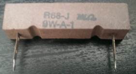
There are many reasons why you need to reduce the level of hum and this
resistor will remove ripple as large as 2.5v when 3.6 amps is flowing,
provided you have filter electrolytics on both side of the resistor to
assist in removing the ripple.
If the letter "R" is in a different position, the value of resistance
would be:
68R = 68Ω
6R8 = 6.8Ω
R68 = 0.68Ω
If you replace the R68 resistor a 6R8 resistor by mistake, the voltage
across it will rise to 25v and if 3.6 amps flows, the wattage will be:
90 watts!!!
The resistor will glow red and burn out.
TESTING A
POSISTOR 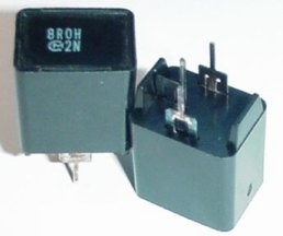
The heavy current that flows when a set is turned ON also causes the posistor
to crack and break and this results in poor purity on the screen - as
the shadow mask gradually becomes magnetic..
Posistors have different resistance values from different manufacturers
and must be replaced with an identical type.
They can be checked for very low resistance when cold but any loose
pieces inside the case will indicate a damaged component.
The resistance of a
"burnt" resistor can sometimes be determined by scraping away the outer
coating - if the resistor has a spiral of resistance-material. You may be
able to find a spot where the spiral has been damaged.
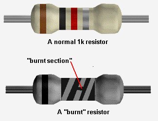
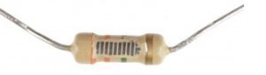
Note the spirals of conductive carbon.
The number of spirals has nothing to with the resistance.
It is the amount of carbon particles in the "track" that
determines the resistance. It is also the thickness and width
of the track that determines the resistance.
And then it is the overall size of the resistor that determines the
wattage.
And then the size of the leads, the closeness to the PCB and
the size of the lands that eventually determines how hot the resistor
will get.
Add the two values and you have an approximate value for the resistor.
You can add a small amount for the damaged section.
This process works very well for damaged wire-wound resistors. They can
be pulled apart and each section of the resistance-wire (nichrome wire)
measured and added to get the full resistance.
There is another way to determine the value of a damaged resistor.
Get a set of resistors of the same wattage as the damaged component and start with a high value.
It's handy to know if the resistor is in the range: 10ohm to 100ohms or
1k to 10k etc, but this is not essential.
Start with a very high value and turn the circuit ON. You can perform
voltage tests and if you know the expected output voltage, decrease the
resistance until this voltage is obtained.
If you do not know the expected voltage, keep reducing the value of
resistance until the circuit works as designed.
This is the best advice in a situation where you do not know the value
of a resistor.
There is a third way to determine the value and this requires measuring
the voltage drop across the resistor and the current-flow. By
multiplying the two you will get a wattage and this must be less than
the wattage of the resistor being replaced.
A SHUNT RESISTOR is a power-resistor
and you will find them in multimeters to provide the CURRENT READING.
This type of resistor is also called A CURRENT SHUNT (Current Shunt
Resistor) or CURRENT SENSE RESISTOR. You will also find them in many
other circuits where the current is required to be measured.
A CURRENT SENSE RESISTOR is always very low resistance so it does not
alter the performance of the circuit.
As current flows though the resistor, a voltage is produced across the
resistor and this voltage is measured by a detecting circuit and the
designer of the circuit already knows how much current is flowing for
each mV developed across the resistor.
But, if too much current flows, these resistors can burn-out and it is
impossible to work out the value of the resistor. Mainly because the
resistance can be as low as 0.1 ohms.
But there is an easy way to replace the resistor.
You will need a set of resistors and the cheapest way to start is with
one ohm resistors (0.25watt).
Place two of them in parallel and connect the project in series with a
multimeter set to 10 amp range and then place a 10 ohm wire-wound
resistor in series with the two instruments and a 12v supply.
You know the current should be about 1.2 amps and if the reading on your
damaged instrument is reading 3 amps, you will need to place another
one-ohm resistor in parallel with the other two. Keep doing this until
the reading on the damaged meter corresponds to the reading on the
functioning meter.
You can add 2 or 3 one-ohm resistors in series to get a fine adjustment.
When you have finished, you can work out the value of the
combination by realising two resistors in parallel is equal to 0.5 ohms
and 3 is 0.33 ohms and 4 is 0.25 ohms.
You may be able to buy shunt resistors of the required value or maybe
use surface mount resistors but you also have to take into account the
size of the original resistor. You must match the size.
MILLI-OHM RESISTORS
Many SHUNT RESISTORS have a very low resistance, mainly because the
resistor is measuring a high current and you don't want a lot of heat to
be created by the resistor and you don't want the voltage you are
measuring to reduce in value.
That's why many SHUNT RESISTORS have a resistance in the MILLI-OHM
range.
A milliohm is ONE THOUSANDTH OF AN OHM and if one amp is flowing through
the resistor, one-millivolt will be developed across it.
If you go through all the samples below, the same reasoning produces 5mV
for a 5 milli-ohm resistor and one quarter of a milli-volt for a 0m25
resistor. Thus 4 amp through this resistor produces 1mV.
Because a high current will flow through the resistor and through the
tracks, there will be some degree of heating and these resistors can get
warm/hot and even overheat and melt the solder. They can also go open
and that's where your skill comes in . . to replace them with the
correct value and wattage.
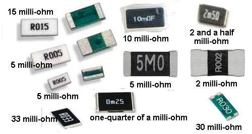
Very low-ohm resistors can be measured in two ways.
Digital multimeters will measure resistors from 0.1 ohms but the leads
add 0.3 ohms to the reading.
You can double-check the reading by adding a 1 ohm resistor and
measuring the milli-ohm resistor with the 1 ohm and with it removed.
If the milliohm resistor is less than 0.1 ohm, you can place the
resistor in series with a multimeter set to current (1 amp) and add an 8
ohm wire wound resistor in series.
Connect the circuit to a variable power supply and increase the current
to exactly 1 amp.
Now measure the voltage across the milli-ohm resistor with a multimeter
set to say 2,000mA.
Each mV will represent 1milliohm.
For example, if the reading is 200mV, the resistor is 200milli-ohm (0.2
ohm).
If the reading is 1,000mV (1volt) the resistor will be 1,000milli-ohm (1
ohm)
A 0m25 resistor (shown above) will show 0.25mV on the multimeter.
A 5M0 resistor above will show 5mV on the multimeter.
A R015 resistor will show 15mV on the multimeter.
Finally we come to the use of a resistor as a SAFETY RESISTOR.
Whenever you are testing a circuit, you need to use a supply that will
not deliver a high current. This will prevent things "going up in smoke"
and burning the PCB tracks. The easiest is to use "dry cells" (AA) and
even though the motor or output device may not work correctly, you can
be sure a short-circuit is not present.
If you are going to use a 12v battery, you need to include a one-ohm
(0.25watt) resistor in series with the positive lead.
This resistor ill allow 250mA to pass with damage. At 500mA the resistor
will get very hot and any current above this will burn out the resistor.
You will be able to work out how quickly the resistor "goes up in smoke"
and compare it to the current requirement of the circuit.
If you leave the resistor permanently in the positive line, it becomes a
SAFETY RESISTOR, but don't forget it will drop a small voltage and if
the circuit takes peaks of current, this resistor can fail.
For the cost of one-cent you can protect a project and make sure it is
working before connecting it permanently to the supply.
FUSIBLE RESISTOR
A
fusible resistor is a low value resistor and should be made of
non-combustible materials.
The value is chosen so it does not get hot during normal operation but
if twice the current flows, it "burns out."
Sometimes it is housed in a non-combustible sleeve.
If you think it has burnt out for no reason, replace it with a one-ohm
resistor (0.25 watt) and feel its temperature. If it is in a DC line,
the voltage across it will be 250mV max.
SUBSTITUTING A
RESISTORYou can get a resistor substitution box for $18.00 plus postage.
I bought one 40 years ago and have only used it ONCE.
Just get a a resistor on jumper leads and if it burns out, you have only lost 10 cents.
When designing a circuit, you may need to go 10% higher or lower to see the effect.
That's why it is best to try a resistor on leads.
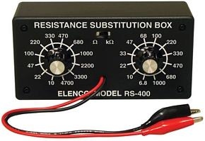
Cost: $18.00 plus postage. Just use an individual
resistor on jumper leads. Save $20.00
TESTING POTENTIOMETERS (variable
resistors)
10-Turn
POTS
To check the
value of a variable resistor, it should be removed from circuit or at
least 2 legs should be removed. A Rheostat is a variable resistor using
only one end and the middle connected to a circuit.
The resistance between the two outside pins is the value marked on the
component and the centre leg will change from nearly zero to the full
resistance as the shaft is rotated.
To find out if the pot is linear or log, simply turn it to half-way and
measure the resistance. It should be half-resistance for a linear pot.
"Pots" generally suffer from "crackle" when turned and this can be fixed
by spraying up the shaft and into the pot via the shaft with a tube fixed to a can of "spray-lubricant"
(contact cleaner).
"Pre-set pots" and "trim pots" are miniature versions of a
potentiometer and they are all tested the same.
The photo
shows a pot, two mini pots and 3 mini trim pots.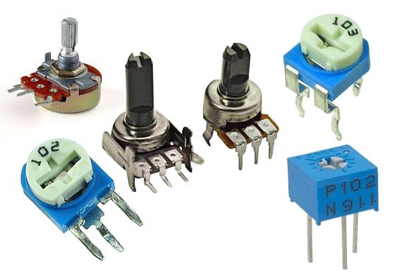
A 10-turn pot is one of the worst items to be
designed. I remove them immediately from any design.
You don't know the position of the wiper. You don't know which way you
are turning the wiper and you can't remember which way you turned the
post "the last time." The screwdriver always falls out of the slot.
If you need fine adjustment, place fixed resistors on each side of the
pot and use a normal mini trim pot with much less resistance.
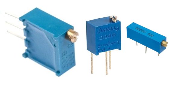
Focus pots are the pots on old-style Cathode Ray TV test or Cathode Ray Oscilloscopes and adjusted the high voltage to the focus anode of the tube. Quite often they get a spot of dirt where the wiper touches the track. Cleaning with spray fixes the bad focus but if the pot is leaking to chassis from inside the pot (due to the high voltage on the terminals) simply remove it from the chassis and leave it floating (this will restore the high voltage to the picture tube) or you can use one from an old chassis.
MAKING YOUR OWN RESISTOR, CAPACITOR, INDUCTOR or DIODE
Quite often you will not have the exact value of resistance or capacitance for a repair.
We have already covered placing resistors and capacitors in parallel and series:
Resistors in Parallel and/or Series
Capacitors in Parallel and/or Series
Here are some extras:
RESISTORS
Two 1k 0.5watt resistors in parallel produces a 470R 1watt resistor.
Two 1k 0.5watt resistors in series produces a 2k 1watt resistor.
CAPACITORS
Two 100n 100v capacitors in series produces a 50n capacitor @200v
INDUCTORS: Two inductors in series - ADD THE VALUES
DIODES: Two 1Amp 400v diodes in series produces a 1Amp 800v diode
Two 1Amp 400v diodes in parallel produces a 2Amp 400v diode
ZENER DIODES: Zener diodes can be connected in series to get a higher voltage.
Two 12v zener diodes in series produces a 24v zener.
CONTINUITY
You can build the circuit on Matrix
Board and add it to your Test Equipment.
Some multimeters have a "buzzer" that detects when the probes are touching
each other or
the resistance between the probes is very LOW. This is called a
CONTINUITY TESTER.
You can use the resistance scale "x1" or "x10" to detect low values of
resistance.
Set the pointer to "0" (right end of the scale) by touching the probes
together and adjusting the "zero ohms" control.
When taking a reading, you will have to decide if a low value of resistance is a short-circuit
or an "operating value."
For instance, the cold resistance of a 12v car globe is very low (about
2 ohms) and it increases (about 6 times) to 12 ohms when hot.
The "resistance of a circuit" may be very low as the electrolytics in
the circuit are uncharged. This may not indicate a true "short-circuit."
The measurement across a diode is not a resistance-value but a
"voltage-drop" and that is why the needle swings nearly full-scale.
Leads and wires and cords have a small resistance and depending on the length of the lead,
this small resistance may be affecting a circuit.
Remember this:
When a circuit takes 1 amp, and the resistance of the leads is 1 ohm,
the voltage drop across the leads will be 1v.
That's why a 12v battery supplying a circuit with these leads will have 11v
at
the circuit.
Note:
Turn off the equipment before making any continuity tests. The presence
of even a small voltage (from an electrolytic) can give a false reading.
You can determine the resistance of a lead very accurately by taking the
example above and applying it to your circuit.
If the battery is 12.6v and the voltage across the circuit is 10v, when
the current is 2.6 amps, the resistance of the "leads" is 12.6 -
10 = 2.6 R=V/I = 2.6/2.6 = 1ohm. By making the lead shorter or using
thicker wire, the resistance will be less and the voltage on the project
will increase.
When taking readings in a circuit that has a number of diodes built-into
IC's (Integrated Circuits) and transistors, some Continuity Testers will beep and give a
false reading.
The following circuit has the advantage of providing a beep when a short-circuit is
detected but does not detect the small voltage drop across a diode. This
is ideal when testing logic circuits as it is quick and you can listen
for the beep while concentrating on the probe. Using a multimeter is
much slower.
CONTINUITY TESTER
You will need lots of "Test Equipment" and they can be built from
circuits in this eBook.
TESTING FUSES, LEADS AND WIRES
Before I
start this section, let me say this: FUSES DON'T PROTECT ANYTHING. In
most cases, when a fuse "blows" many of the components in the circuit
will be damaged too.
If these components are regulators, diodes, thyristors or transistors;
you will also have to find out what caused them to be damaged.
Just replacing the damaged parts may not be successful. They will just
"blow" again.
This is just a notification.
You may be lucky. The fuse may "worn out" or just "died" but
a one amp fuse will BLOW very quickly if a short-circuit is present and
trip a 15 amp circuit breaker !!!
Testing fuses, leads and wires
comes under the heading TESTING for CONTINUITY. Turn off all
power to the equipment before testing for shorts and continuity. Use the
low resistance "Ohms Scale" or CONTINUITY range on your multimeter. All
fuses, leads and wires should have a low, very low or zero resistance. This
proves they are working.
A BLOWN FUSE
The appearance of a fuse after it has "blown" can tell you a lot about the fault in the
circuit.
If the inside of the glass tube (of the fuse) is totally blackened, the
fuse has been damaged very quickly. This indicates a very high current
has passed through the fuse.
Depending on the rating of the fuse, (current rating)
you will be able to look for components that can pass a high current when
damaged - such as high power transistors, FETs, coils, electrolytics.
Before re-connecting the supply, you should test the "SUPPLY RAILS" for
resistance. This is done by measuring them on a low OHMs range in one
direction then reverse the leads to see if the resistance is low in the
other direction.
A reading can be very low at the start because electrolytics need time
to charge-up and if the reading gradually increases, the power rail does
not have a short. An overload can occur when the supply voltage rises to
nearly full voltage, so you sometimes have to fit a fuse and see how
long it takes to "blow."
If the fuse is just slightly damaged, you will need to read the next
part of this eBook, to see how and why this happens:
FAST AND SLOW BLOW FUSES
There are many different sizes, shapes and ratings of a fuse. They are
all current ratings as a fuse does not have a voltage rating. Some fuses
are designed for cars as they fit into the special fuse holders. A fuse
can be designed for 50mA, 100mA, 250mA, 315mA, 500mA, 1Amp, 1.5amp,
2amp, 3amp, 3.15amp 5amp, 10amp, 15amp, 20amp, 25amp, 30amp,
35amp, 50amp and higher.
Some fuses are fast-blow and some are slow-blow.
A "normal" fuse consists of a length of thin wire. Or it may be a loop
of wire or a strip of thin sheet that is thin near the middle of the fuse. This is the section
that will "burn-out."
A "normal" fuse is a fast-blow fuse. For instance, a 1amp fuse will
remain intact when up to 1.25 amp flows. When a circuit is turned on, it
may take 2-3 amps for a very short period of time and a normal 1 amp
fuse will get very hot and the wire will stretch but not "burn-out." You
can see the wire move when the supply turns on.
If the current increases to 2amps, the fuse will still remain intact. It
needs about 3 amp to heat up the wire to red-hot and burn out.
If the current increases to 5 amp, the wire VOLATILISES (burns-out) and
deposits carbon-black on the inside of the glass tube.
A slow-blow fuse uses a slightly thicker piece of wire and the fuse is
made of two pieces of wire joined in the middle with a dob of
low-temperature solder. Sometimes one of the pieces of wire is a spring
and when the current rises to 2.5 amp, the heat generated in the wire
melts the solder and the two pieces of wire "spring apart."
A slow-blow fuse will allow a higher current-surge to pass through the
fuse and the wire will not heat up and sag.
Thus the fuse is not gradually being damaged and it will remain in a
perfect state for a long period of time.
A fuse does not protect electronic equipment from failing. It acts AFTER
the equipment has failed.
It will then protect a power supply from delivering a high current to a
circuit that has failed.
If a slow-blow fuse has melted the solder, it could be due to a slight
overload, slight weakening of the fuse over a period of time or the
current-rating may be too low.
You can try another fuse to see what happens.
You can replace a fast-acting fuse (normal fuse) with a slow blow if the fast-acting
fuse has been replaced a few times due to deterioration when the
equipment is turned on.
But you cannot replace a slow-blow fuse with a fast acting fuse as it
will be damaged slightly each time the equipment is turned on and
eventually fail.
Fuses below about 100mA are very hard to make and very unreliable.
Many circuits take a high current when turned to charge the electrolytics and a 100mA (or 50mA or 63mA fuse) will bow and stretch and change shape, every time the equipment is turned ON.
Eventually it will break, due to it heating-up and stretching.
To produce a reliable fuse below 100mA, some manufacturers have placed a resistor inside the fuse and connected it to a spring. One end of the resistor is soldered to a wire with low-temperature metal and when the resistor gets hot, the metal softens and the spring pulls the resistor away from the wire.
Quite often you can heat up the metal and connect the wire and the fuse is perfect.
This type of fuse is called a DELAY fuse and the current rating is shown on the end-cap.
The value of the resistor determines the current rating.
There is a small voltage across this type of fuse and it means the circuit sees a slightly lower voltage than the supply voltage.
The third photo shows the "pot of solder" or low-temp metal and a wire connected to a spring. The heat generated in the wire is passed to the solder and it softens. The spring pulls the two components apart. You can smash the glass and set up the fuse in the two fuse-holders and repair the fuse while you wait for a new fuse to arrive.
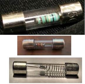
TESTING
COILS, INDUCTORS and YOKES
Coils, inductors, chokes and yokes are just
coils (turns) of wire. The
wire may be wrapped around a core made of iron or ferrite.
It is labeled "L" on a circuit board.
You can test this component for continuity between the ends of the
winding and also make sure there is no continuity between the winding
and the core.
The winding can be less than one ohm, or greater than 100 ohms. A coil of wire is also called an INDUCTOR and it might look like a very
simple component, but it can operate in a very complex way.
The way it works is a discussion for another eBook. It is important to
understand the turns are insulated but a slight fracture in the
insulation can cause two turns to touch each other and this is called a
"SHORTED TURN" or you can say the inductor has "SHORTED TURNS."
When this happens, the inductor allows the circuit to draw MORE CURRENT.
This causes the fuse to "blow."
The quickest way to check an inductor is to replace it, but if you want
to measure the inductance, you can use an INDUCTANCE METER. You can then
compare the inductance with a known good component.
An inductor with a shorted turn will have a very low or zero inductance,
however you may not be able to detect the fault when it is not working
in a circuit as the fault may be created by a high voltage generated
between two of the turns.
Faulty yokes (both horizontal and vertical windings) can cause the
picture to reduce in size and/or bend or produce a single horizontal
line.
A TV or monitor screen is the best piece of Test Equipment as it has
identified the fault. It is pointless trying to test the windings
further as you will not be able to test them under full operating
conditions.
The fault may not show up when a low voltage (test voltage) is applied.
MEASURING AND TESTING INDUCTORS
Inductors are measured with an INDUCTANCE METER
but the value of some inductors is very small and some Inductance Meters
do not give an accurate reading.
The solution is to measure a larger inductor and note the reading. Now
put the two inductors in SERIES and the values ADD UP - just like
resistors in SERIES. This way you can measure very small inductors.
VERY CLEVER!
Question from a reader: Can I add an inductor to stop a fuse blowing?
This is the detection and prevention of current that exists for a very short period of time.
A fuse detects an excess of current that occurs over a very long period of time and they are entirely two different "detectors."
One cannot assist the other in any way.
An inductor is basically a coil of wire. It may be thick or thin wire. The value of the inductor is a combination of the number of turns and the material on which the wire is wound.
The value of an inductor does not change over say a period of 20 years but it can go faulty by the enamel cracking and two turns touching. This can also be due to the difference in voltage between the two turns creating a spark between the turns and creating a "short."
When you test it, the high voltage is not present and it will test ok.
You may not think a few turns of wire will have any effect on improving a circuit, but spikes are very high frequency and the inductor will have a very big effect on reducing them.
An inductor (say 100uH) can be produced in many different sizes and the thickness of the wire will be important as it determines the current that can flow through the inductor.
The term "inductor" also includes those with two or more windings and these components are called TRANSFORMERS. These devices can get "shorts" and "leaks" between the windings and sparks can be seen between the windings. These sparks do not occur when you are testing them on test-equipment so the only way to guarantee success is to replace it with an identical replacement.
TESTING SWITCHES and RELAYS
Switches and relays have contacts that open and close mechanically and you can test them for CONTINUITY. However these components can become intermittent due to dirt or pitting of the surface of the contacts due to arcing as the switch is opened.
It is best to test these items when the operating voltage and current is present as they quite often fail due to the arcing. A switch can work 49 times then fail on each 50th operation. The same with a relay. It can fail one time in 50 due to CONTACT WEAR.
If the contacts do not touch each other with a large amount of force and with a large amount of the metal touching, the current flowing through the contacts will create HEAT and this will damage the metal and sometimes reduce the pressure holding the contact together.
This causes more arcing and eventually the switch heats up and starts to burn. Switches are the biggest causes of fire in electrical equipment and households.
A relay also has a set of contacts that can cause problems.
There are many different types of relays and basically they can be put into two groups.
1. An electromagnetic relay is a switch operated by magnetic force. This force is generated by current through a coil. The relay opens and closes a set of contacts.
The contacts allow a current to flow and this current can damage the contacts. Connect 5v or 12v to the coil (or 24v) and listen for the "click" of the points closing. Measure the resistance across the points to see if they are closing.
You really need to put a load on the points to see if they are clean and can carry a current.
The coil will work in either direction.
If not, the relay is possibly a CMOS relay or Solid State relay.
2. An electronic relay (Solid State Relay) does not have a winding. It works on the principle of an opto-coupler and uses a LED and Light Activated SCR or Opto-TRIAC to produce a low resistance on the output. The two pins that energise the relay (the two input pins) must be connected to 5v (or 12v) around the correct way as the voltage is driving a LED (with series resistor). The LED illuminates and activates a light-sensitive device.
In most cases you do not know what is inside a Solid State Relay and two
things can fail.
The LED can be damaged and the OPTO TRIAC may have failed.
Firstly you have to make sure if the SSR is the faulty item.
You can replace with another of the same type but if this is not
possible, you can make one of the circuits above and see if closing the
output terminals will allow the project to operate.
The next test is to measure the voltage across the input.
If it is between 2v and 4v, the LED is possibly working.
If it is above 5v, the SSR may have an internal resistor.
You will then have to measure the current entering the input terminals.
This current will be between 7mA and 25mA.
You also bridge across the output terminals to determine if the project
is correctly connected to the SSR.
All this requires CARE as the output terminals may be live to the mains,
while the input terminals are electrically isolated from the output with
an SSR that is optically connected between input and output.
TESTING REED SWITCHES
A wire or lead comes out each end for soldering to the reed switch to the project. The two "blades" inside the switch are made from a material that can be magnetised but does not retain its magnetism. This effect is called "temporally magnetised" (not permanently magnetised) and really only "passes" magnetism from one end to the other when in the presence of a magnet. One of the blades is made of a soft material and it will bend very easily. The other one is much stiffer.
When a magnet is placed under the two blades (or on top), the magnetism from the
magnet is passed to the two blades (INDUCTION or MUTUAL INDUCTION -
commonly called INDUCED) and it produces a very weak magnet (in the
blade)
that is identical to the powerful magnet as far as the position of the
north and south poles are concerned). Initially it produces a N-S and
N-S set of poles and this makes the two blades click together because
the top blade will be South at the contact and the bottom blade will be
North.
When the two blades click together the magnetism runs through the two
blades and keeps them together. The
two blades attract and the switch is closed.
When the magnet is removed, the magnetism in the two blades ceases and
the two blades move apart.
Since there is a very small amount of movement in the top blade, this
switch has a limited number of operations. Eventually it will fail. It
is a mechanical device and is not suited for detecting a spinning shaft
as 100,000 revolutions will very quickly weaken the switch.
If the switch does not make contact or remains closed, the moveable blade can be
cracked or broken. This can be very hard to see. So replace the
switch.
LATCHING
REED SWITCHA "normal" reed switch can be converted into a LATCHING REED SWITCH by carefully placing a magnet below the switch and moving it away so the two blades open. Now move it slightly closer but do not allow the blades to close.
This is called putting a "SET" on the switch and the two blades will have a small magnetic effect "induced" in them but not enough to close the contacts:
Now bring a strong magnet up to the reed switch on the other side of the glass tube with the north pole above the north of the lower magnet. This effect will increase the INDUCED MAGNETISM in the blades and close the contacts:
Remove the top magnet and the lower magnet will induce enough magnetism into the blades to keep them closed:
Now bring the upper magnet near the reed switch with the south pole above the north pole of the lower magnet. (In other words: AROUND THE OTHER WAY) This will have the effect of reducing the induced magnetism in the blades and a point will be reached when the two contacts will separate:

Remove the top magnet and the switch will remain separated because the lower magnet will not have sufficient influence on the blades to close the contact:
SAFETY (when testing ANYTHING)
You have to apply complete safety measures when testing ANYTHING. Even a
5watt cell-phone charger that plugs into the wall needs "protection
measures" when "pulling it apart."
I use two 15VA transformers (or 30VA) connected "back-to-back" to
produce 240v AC output but with a voltage that is totally isolated from
the mains and has a very small current capability. When a
short-circuit occurs, you can hear the transformers "hum" so you can
disconnect the problem. But nothing "blows up."
![]()
![]()
This is called an ISOLATION TRANSFORMER and prevents things "blowing up
in your face" if a short-circuit is present.
The same approach applies to testing all sorts of modules and devices
that operate on 6v, 9v, or 12v.
Test them with a weak battery and preferably not alkaline cells as they
can still deliver 2 amps or more and this can cause damage.
The battery should be weak (500mA or less) and when you have tested the
project, you can connect a quality battery.
Even a "current limiting" power supply is not a suitable supply as the
voltage drops when a load is present and the project will fail to work.
CAPACITORS
Capacitors are one of the most difficult things to test.
That's
because they don't give a reading on a multimeter and their value can
range from 1p to 100,000u.
A faulty capacitor may be "open" when measured with a multimeter,
and a
good capacitor will also be "open."
You need a piece of test equipment called a CAPACITANCE METER to measure
the value of a capacitor.
HOW A CAPACITOR WORKS
There are two ways to describe how a capacitor works. Both are correct
and you have to combine them to get a full picture.
A capacitor has INFINITE resistance between one lead and the other
(an electrolytic has a high resistance when it is fully charged).
This means no current flows through a capacitor. But it works in
another way.
Suppose you have a strong magnet on one side of a door and a piece of
metal on the other. By sliding the magnet up and down the door, the
metal rises and falls.
The metal can be connected to a pump and you can pump water by sliding
the magnet up and down.
A capacitor works in exactly the same way.
If you raise a voltage on one lead of a capacitor, the other lead will rise to the same voltage. This
needs more explaining - we are keeping the discussion simple.
It works just like the magnetic field of the magnet through a door.
The next concept is this:
Capacitors are
equivalent to a tiny rechargeable battery.
They store energy when the supply-voltage is present and release it when
the supply drops.
These two concepts can be used in many ways and that's why capacitors
perform tasks such as filtering, time-delays, passing a
signal from one stage to another and
create many different effects in a circuit.
CAPACITOR VALUES
The basic unit of capacitance is the FARAD. (C)
This is the value used
in all equations, but it is a very large value. A one FARAD capacitor
would be the size of a car if made with plates and paper. Most
electronic circuits use capacitors with smaller values such as
1p to 1,000u.
1p is about equal to
two parallel wires 2cm long. 1p is one picofarad.
The easiest way to understand capacitor values is to start with a value
of 1u. This is one microfarad and is one-millionth of a Farad. A 1
microfarad capacitor is about 1cm long and the diagram shows a 1u
electrolytic.
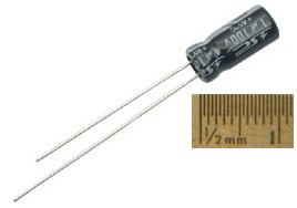
Smaller capacitors are ceramic and they look like the following. This is a 100n (0.1u)ceramic:
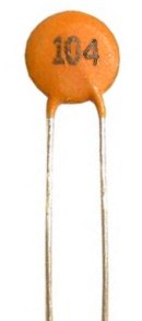
To read the value on a capacitor you need to know a few facts.
The basic value of capacitance is the FARAD.
1 microfarad is one millionth of 1 farad.
1 microfarad is divided into smaller parts called nanofarad.
1,000 nanofarad = 1 microfarad
Nanofarad is divided into small parts called picofarad
1,000 picofarad = 1 nanofarad.
Recapping:
1p = 1 picofarad. 1,000p = 1n ( 1 nanofarad)
1,000n = 1u (1 microfarad)
1,000u = 1millifarad
1,000,000u = 1 FARAD.
Examples:
All ceramic capacitors are marked in "p" (puff")
A ceramic with 22 is 22p = 22 picofarad
A ceramic with 47 is 47p = 47 picofarad
A ceramic with 470 is 470p = 470 picofarad
A ceramic with 471 is 470p = 470 picofarad
A ceramic with 102 is 1,000p = 1n
A ceramic with 223 is 22,000p = 22n
A ceramic with 104 is 100,000p = 100n = 0.1u
TYPES OF CAPACITOR
For testing purposes, there are two types of capacitor.
Capacitors from 1p to 100n are non-polar and can be inserted into a
circuit around either way.
Capacitors from 1u to 100,000u are electrolytics and are polarised.
They must be fitted so the positive lead goes to the supply voltage and
the negative lead goes to ground (or earth).
There are many different sizes, shapes and types of capacitor. They are
all the same. They consist of two plates with an insulating material
between. The two plates can be stacked in layers or rolled together.
The important factor is the insulating material. It must be very thin to
keep things small. This gives the capacitor its VOLTAGE RATING.
If a capacitor sees a voltage higher than its rating, the voltage will
"jump through" the insulating material or around it.
If this happens, a carbon deposit is left behind and the capacitor
becomes "leaky" or very low resistance, as carbon is conductive.
CERAMIC CAPACITORS
Nearly all small capacitors are ceramic capacitors as this
material is cheap and the capacitor can be made in very thin layers to
produced a high capacitance for the size of the component. This is
especially true for surface-mount capacitors.
All capacitors are marked with a value and the basic unit is: "p" for
"puff" However NO surface mount capacitors are marked and they are
very difficult to test.
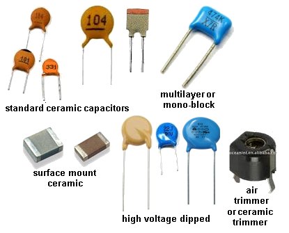
| VALUE: | VALUE WRITTEN ON THE COMPONENT: |
| 0.1p 0.22p 0.47p 1.0p 2.2p 4.7p 5.6p 8.2p 10p 22p 47p 56p 100p 220p 470p 560p 820p 1,000p (1n) 2200p (2n2) 4700p (4n7) 8200p (8n2) 10n 22n 47n 100n 220n 470n 1u |
0p1 0p22 0p47 1p0 2p2 4p7 5p6 8p2 10 or 10p 22 or 22p 47 or 47p 56 or 56p 100 on 101 220 or 221 470 or 471 560 or 561 820 or 821 102 222 472 822 103 223 473 104 224 474 105 |
POLYESTER, POLYCARBONATE,
POLYSTYRENE, MYLAR, METALLISED POLYESTER, ("POLY"), MICA and other types
of CAPACITOR
There are many
types of capacitor and they are chosen for their reliability, stability,
temperate-range and cost.
For testing and repair work, they are all the same. Simply replace with
exactly the same type and value.
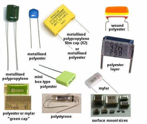
Capacitor Colour Code Table
| Colour | Digit A |
Digit B |
Multiplier D |
Tolerance (T) > 10pf |
Tolerance (T) < 10pf |
Temperature Coefficient (TC) |
| Black | 0 | 0 | x1 | ± 20% | ± 2.0pF | |
| Brown | 1 | 1 | x10 | ± 1% | ± 0.1pF | -33x10-6 |
| Red | 2 | 2 | x100 | ± 2% | ± 0.25pF | -75x10-6 |
| Orange | 3 | 3 | x1,000 | ± 3% | -150x10-6 | |
| Yellow | 4 | 4 | x10,000 | ± 4% | -220x10-6 | |
| Green | 5 | 5 | x100,000 | ± 5% | ± 0.5pF | -330x10-6 |
| Blue | 6 | 6 | x1,000,000 | -470x10-6 | ||
| Violet | 7 | 7 | -750x10-6 | |||
| Grey | 8 | 8 | x0.01 | +80%,-20% | ||
| White | 9 | 9 | x0.1 | ± 10% | ± 1.0pF | |
| Gold | x0.1 | ± 5% | ||||
| Silver | x0.01 | ± 10% |
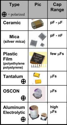
ELECTROLYTIC and TANTALUM CAPACITORS
Electrolytics and Tantalums are the same for testing purposes but their
performance is slightly different in some circuits. A tantalum is
smaller for the same rating as an electrolytic and has a better ability
at delivering a current. They are available up to about 1,000u, at about
50v but their cost is much higher than an electrolytic. A tantalum is
know for short-circuiting for no apparent reason in some TV sets. It may
have been due to the faulty manufacture.
Electrolytics are available in 1u, 2u2 3u3 4u7 10u, 22u, 47u, 100u,
220u, 330u, 470u, 1,000u, 2,200u, 3,300u, 4,700u, 10,000u and higher.
The "voltage" or "working voltage" can be: 3.3v, 10v,
16v, 25v, 63v, 100v, 200v and higher. Do not exceed the voltage marked
on the electrolytic by any more than a few volts. A 1,000u 25v electro
was subjected to 35v and it got hot and exploded!!
There is also another important factor that is rarely covered in text
books. It is RIPPLE FACTOR.
This is the amount of current that can enter and leave an electrolytic. This current heats up the electrolytic and that
is why some
electrolytics are much larger than others, even though the capacitance
and voltage-ratings are the same. Ripple factors are very hard to
determine, so the size of the electrolytic is your best decision.
If you replace an electrolytic with a "miniature" version, it will heat
up and have a very short life. This is especially important in power
supplies where current (energy) is constantly entering and exiting the
electrolytic as its main purpose is to provide a smooth output from a
set of diodes that delivers "pulsing DC." (see "Power Diodes").
A miniature version of an electrolytic will have a lower ripple factor
- it will be capable of handling less current entering and leaving. This
value is very important in a power supply. A miniature version will get
too hot.
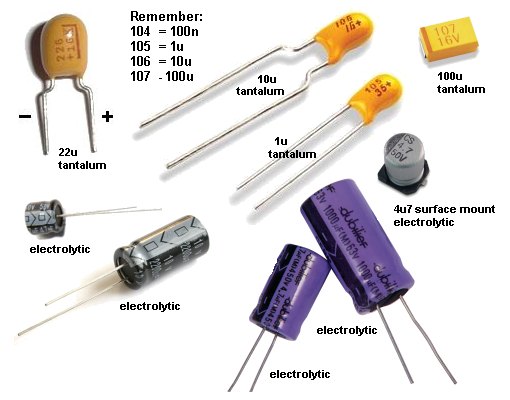
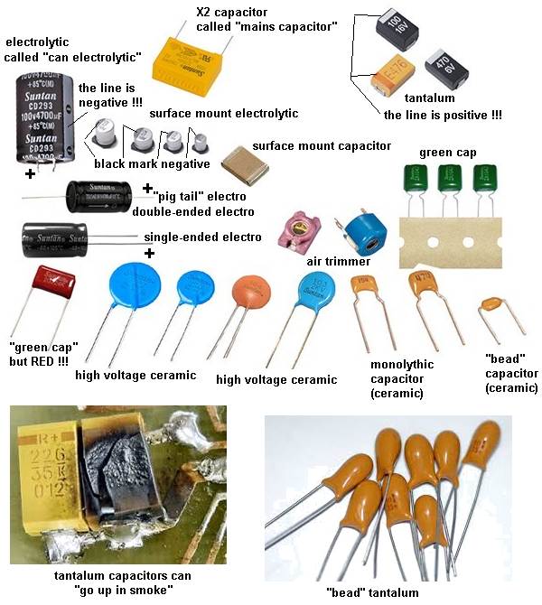
PARALLEL and SERIES CAPACITORS
Capacitors can be connected in PARALLEL and/or SERIES for a number of reasons.
1. If you do not have the exact value, two or more connected in parallel
or series can produce the value you need.
2. Capacitors connected in series will produce one with a higher voltage
rating.
3. Capacitors connected in parallel will produce a larger-value
capacitance.
Here are examples of two equal capacitors connected in series or
parallel and the results they produce:
NON-POLAR CAPACITORS (ELECTROLYTICS)
Electrolytics are also available in non-polar values.
It sometimes has the letters "NP" on the component. Sometimes the leads
are not identified.
This is an electrolytic that does not have a positive and negative lead
but two leads and either lead can be connected to the positive or
negative of the circuit.
These electrolytics are usually connected to the output of an amplifier
(such as in a filter near the speaker) where the
signal is rising and falling.
A non-polar electrolytic can be created from two ordinary electrolytics
by connecting the negative leads together and the two positive leads
become the new leads.
For example: two 100u 63v electrolytics will produce a 47u 63v
non-polar electrolytic.
In the circuit below, the non-polar capacitor is replaced with two
electrolytics.
MAKING A NON-POLAR ELECTROLYTIC
A normal electrolytic must be connected the correct way in a circuit because it has a thin insulating layer covering the plates that has a high resistance.
If you connect the electrolytic around the wrong way, this layer "breaks-down" and the resistance of the electrolytic becomes very small and a high current flows. This heats up the electrolytic and the current increases. Very soon the capacitor produces gasses and explodes.
One big mistake in many text books shows how to make a non-polar electrolytic by connecting two "back-to-back."
They claim 2 x 100u connected back-to-back is equal to 47u.
This appears to be case when testing on a meter but the meter simply charges them for a short period of time to get a reading.
If you allow them to charge fully you will find the reverse electrolytic has a very small voltage across it.
Secondly, when you are charging them, you are putting a high current through the reverse electrolytic and damaging the layer.
To prevent this, you need to add two diodes as shown in the diagram.
In addition, 2 x 100u "back-to-back" is very near 100u.
If you are using 2 capacitors back-to-back in a low voltage circuit (without the two diodes), the result will be 47u because a capacitor in reverse will produce its full capacitance, even though it is being charged in the wrong direction. This will only the case when a low voltage is applied and the leakage is very small.
If these two capacitors are left for a long period of time, the "reverse electro" will leak due to the fact that the isolating layer inside the electro is seeing a reverse voltage. This means the current flowing though it will also flow through the other electro and the correctly placed electro will keep charging so that the whole supply voltage will eventually appear across the correctly placed electro.
Here is a question from a reader:
I have an amplifier with 2 x2,200u electrolytics on the output of a bridge. Can I replace them with a single 10,000u?
You need to look at the circuit of your
amplifier. The two
2,200u electrolytics are possibly connected as shown in the circuit
above and you will notice they are joined to produce a positive rail and
a negative rail with zero (called earth) in the centre.
This forms two different circuits with the top electrolytic filtering
the positive rail and the bottom electro filtering the negative rail.
They must be connected to the zero volts rail.
A single 10,000u cannot be connected to the 0v rail and cannot be
substituted for the two electro's.
You can easily determine if the two electro's are connected as shown
above.
Test the positive terminal of each electro by placing the negative of
the meter on the chassis.
If the positive of one electro has zero volts, it will be the lower
electro in the diagram above. The negative terminal of the lower electro will
have a minus voltage on it.
Here is a problem. The circuit operates a solenoid for a short period of time with the current that flows through the 2,000u electrolytic when it is charging (when the switch is in the "siding" position).
When the switch is in the "Main" position, the energy in the 2,000u
electrolytic is passed to the solenoid and it operates much more
strongly than when the switch is in the other position.
WHY?
 When
you connect the uncharged 2,000u electrolytic across the other two fully
charged electrolytics, the charging current is so high that the power
supply cannot deliver nearly enough current and it takes a lot of the
charging current from the two 1,000u electros.
When
you connect the uncharged 2,000u electrolytic across the other two fully
charged electrolytics, the charging current is so high that the power
supply cannot deliver nearly enough current and it takes a lot of the
charging current from the two 1,000u electros.
This means the "two full buckets of water" and going to be dumped into
the "empty bucket" with the result that the voltage is going to drop to
about half-voltage at the beginning of the cycle. The only thing that is
going to raise the voltage to full voltage is the energy from the power
supply. But this will take a long time and the solenoid will only see
about half the energy passing between the electros. To solve this
problem, the two 1,000u electros need to be replaced with 2,200u and now
you can work out how much the energy will rise.
When an electrolytic is in a power supply, the voltage entering the electrolytic is rising and falling. This is called UNFILTERED DC. This voltage is rising to the peak and falling to zero, either 100 or 120 times per second. The electrolytic charges and this rising and falling voltage "disappears from view" because the electrolytic stores the maximum voltage and the diode on the power supply prevents the voltage going back into the "mains."
After a while, the incoming voltage only has a tiny effect on charging the electrolytic a few millivolts on each cycle to replace the tiny amount of charge lost in the electrolytic due to leakage.
But when you take current from the power supply, the incoming voltage will deliver this current during the time when it is as high as the voltage you are getting from the power supply, but when it is falling, the electrolytic delivers the energy.
The electrolytic is not as "strong" as the incoming energy and that's why the output voltage drops a few volts on each half cycle.
This means current is entering and leaving the electrolytic and the electrolytic has a very small internal resistance.
By simple ohm's law, the heat generated inside the electro is determined by I2R and this heats the electro.
You can get small, medium and large electrolytics with exactly the same capacity and voltage rating.
The only difference is the temperature rise (and the ripple factor - discussed below). A small electro will heat up to a higher temperature.
It is impossible to predict what will happen so you need to fit the smallest and cover it with something so that it heat up. Feel the temp after an hour. Then fit the other different sizes and compare your results.
Testing 1,000u electrolytics may show they all have the same 80milliohm internal impedance, so it is just the heat dissipation from the can that will reduce the temperature rise.
VOLTAGE RATING OF CAPACITOR
Capacitors have a voltage rating, stated as WV for working
voltage, or WVDC. This specifies the maximum voltage that can be
applied across the capacitor without puncturing the dielectric. Voltage
ratings for "poly," mica and ceramic capacitors are
typically 50v to 500 VDC. Ceramic capacitors with ratings of 1kv to 5kv
are also available. Electrolytic capacitors are commonly available in
6v, 10v 16v, 25v, 50v, 100v, 150v, and 450v ratings.
THE SIZE OF A CAPACITOR - RIPPLE FACTOR
The size of a capacitor depends on a number of factors, namely the value
of the capacitor (in microfarads etc) and the voltage rating. But there
is also another factor that is most important. It is the RIPPLE FACTOR.
Ripple Factor is the amount of current-fluctuation the capacitor
(electrolytic) can withstand without getting too hot.
When current flows in and out of an electrolytic, it gets hot and this
will eventually dry-out the capacitor as some of the liquid inside the
capacitor escapes through the seal. It's a very slow process but over a
period of years, the capacitor looses its capacitance.
If you have two identical 1,000u 35v electrolytics and one is
smaller, it will get hotter when operating in a circuit and that's why
it is necessary to choose the largest electrolytic.
CAUTION
If a capacitor has a voltage rating of 63v, do not put it in a 100v circuit
as the insulation (called
the dielectric) will be punctured and the capacitor will
"short-circuit." It's ok to replace a 0.22uF 50WV capacitor with 0.22uF 250WVDC.
An electrolytic will withstand 110% voltage - that is 10% higher
than the marked value, but a voltage above this will leak through the
oxide insulation and eventually create a pin-hole short-circuit.
SAFETY
A capacitor can store a charge for a period of time after the equipment is
turned off. High voltage electrolytic caps can pose a safety hazard. These capacitors are in power
supplies and some have a resistor across them, called
a bleed resistor, to discharge the cap after power is switched off.
If
a bleed resistor is not present the cap can retain a
charge after the equipment is unplugged.
How to discharge a capacitor
Do not use a screwdriver to short between the terminals as this will
damage the capacitor internally and the screwdriver.
Use a 1k 1 watt or 3watt or 5watt resistor on jumper leads (or held with
pliers) and keep them connected
for up to 15 seconds to fully discharge the electro. You can even go as
low as 100 ohms or 10 ohms for a 25v or 35v electrolytic and watch the
spark. Then test it with a voltmeter to make sure all the energy has been removed.
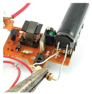
Here is a 120u 330v electrolytic from a flash circuit in an old-fashioned film camera.
If the flash does not "fire," the electrolytic will be charged to about 350 volts !!
Use a 1k resistor (held with pliers) to slowly discharge it. It may take 15 seconds to fully discharge.
TESTING A CAPACITOR
There are two things you can test with a multimeter:
1. A short-circuit within the capacitor
2. Capacitor values above 1u.
You can test capacitors in-circuit for short-circuits. Use the x1 ohms range.
To test a capacitor for leakage, you need to remove it or at least one lead must be removed. Use the x10k range on an analogue or digital multimeter.
For values above 1u you can determine if the capacitor is charging by using an analogue meter. The needle will initially move across the scale to indicate the cap is charging, then go to "no deflection." Any permanent deflection of the needle will indicate leakage.
You can reverse the probes to see if the needle moves in the opposite direction. This indicates it has been charged. Values below 1u will not respond to charging and the needle will not deflect.
This does not work with a digital meter as the resistance range does not output any current and the electrolytic does not charge.
Rather than spending money on a capacitance meter, it is cheaper to replace any suspect capacitor or electrolytic.
Capacitors can produce very unusual faults and no piece of test equipment is going to detect the problem.
In most cases, it is a simple matter to solder another capacitor across the suspect component and view or listen to the result.
This saves all the worry of removing the component and testing it with equipment that cannot possibly give you an accurate reading when the full voltage and current is not present.
It is complete madness to even think of testing critical components such as capacitors, with TEST EQUIPMENT. You are fooling yourself. If the Test Equipment says the component is ok, you will look somewhere else and waste a lot of time.
FINDING THE VALUE OF A
CAPACITOR
If you want to find the value of a surface-mount capacitor or one where
the markings have been removed, you will need a CAPACITANCE METER. Here
is a simple circuit that can be added to your meter to read capacitor
values from 10p to 10u.
The full article can be found
HERE.
ADD-ON CAPACITANCE METER
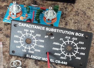
Cost: $18.00 plus postage. Just use individual capacitors
and solder them directly to the board.
You can get a kit or a ready-made piece of test gear called
CAPACITOR SUBSTITUTION BOX and also RESISTOR SUBSTITUTION
BOX.
I bought one of each 30 years ago and I have only used them ONCE.
They appear to be very handy but when you are testing a circuit, you
want the component next to the other parts.
It is just as easy to pick the component you need from your junk box and
connect it to the circuit via jumper leads. If the resistor burns out,
you can throw it away.
REPLACING A
CAPACITOR
Always replace a capacitor
with the exact same type.
A capacitor may be slightly important in a circuit or it might be
extremely critical.
A manufacturer may have
A capacitor just doesn't have a "value of capacitance."
It may also has an effect called "tightening of the rails."
In other words, a capacitor has the ability to react quickly and either absorb or deliver energy to prevent spikes or fluctuations on the rail.
This is due to the way it is constructed. Some capacitors are simply plates of metal film while others are wound in a coil. Some capacitors are large while others are small.
They all react differently when the voltage fluctuates.
Not only this, but some capacitors are very stable and all these features go into the decision for the type of capacitor to use.
You can completely destroy the operation of a circuit by selecting the wrong type of capacitor.
No capacitor is perfect and when it gets charged or discharged, it appears to have a small value of resistance in series with the value of capacitance. This is known as "ESR" and stands for EQUIVALENT SERIES RESISTANCE. This effectively makes the capacitor slightly slower to charge and discharge.
We cannot go into the theory on selecting a capacitor as it would be larger than this eBook so the only solution is to replace a capacitor with an identical type.
However if you get more than one repair with identical faults, you should ask other technicians if the original capacitor comes from a faulty batch.
The author has fixed TV's and fax machines where the capacitors have been inferior and alternate types have solved the problem.
Some capacitor are suitable for high frequencies, others for low frequencies.
With high frequency circuits, you cannot substitute a capacitor by connecting it to long jumper leads. The capacitor MUST be soldered directly into the circuit.
We get a lot of enquiries about replacing a capacitor in say an e-bike with 470u 80v. Many electronics shops only supply 35v or 63v and the voltage rating needs to be about 80v to cater for the high voltage battery packs.
The only solution I can come up with is parallel/series. This will not guarantee equal division of the voltage across all capacitors but will be acceptable. For a 470u 80v we need four 470u at 63v, connected like this:
 You need four because the first two on the left are in series to obtain
120v capability and this produces 235u. The second string adds 235u to
get 470u at over 100v
You need four because the first two on the left are in series to obtain
120v capability and this produces 235u. The second string adds 235u to
get 470u at over 100v The volume of the 4 capacitors (electrolytics) must be equal or greater than the original to maintain the same ripple-factor.
DECOUPLING CAPACITORS
A Decoupling Capacitor can severe one, two or three functions. You need
to think of a decoupling capacitor as a miniature battery with the
ability to deliver a brief pulse of energy when ever the line-voltage
drops and also absorb a brief pulse of energy when ever the line voltage
rises (or spikes).
Decoupling capacitor can range from 100n to 1,000u.
100n capacitors are designed to absorb spikes and also have the effect
of tightening-up the rails for high frequencies. They have no effect on
low frequencies such as audio frequencies.
These capacitors are generally ceramic and have very low internal
impedance and thus they can operate at high frequencies.
Capacitors above about 10u are used for decoupling and these are nearly
always electrolytics.
Decoupling means "tightening-up the power rails." The electrolytic acts
just like a miniature rechargeable battery, supplying a small number of
components in a circuit with a smooth and stable voltage.
The electrolytic is usually fed from a dropper resistor and this
resistor charges the electrolytic and adds to the ability of the
electrolytic to create a "separate power supply."
These two components help remove spikes as an electrolytic cannot remove
spikes if connected directly to the supply rails - it's internal
impedance is high and the spikes are not absorbed.
Decoupling capacitors are very difficult to test.
They rarely fail but if a project is suffering from unknown glitches and
spikes, it is best to simply add more 100n decoupling caps on the
underside of the board and replace all electrolytics.
Some small electrolytics will dry out due to faulty manufacture and
simply replacing every one on a board will solve the problem.
Some of the functions of a decoupling capacitor are:
Removing ripple - hum or buzz in the background of an amplifier
Removing glitches or spikes.
Separating one stage from another to reduce or remove MOTOR-BOATING - a
low frequency sound due to the output putting a pulse on the power rails
that is picked up by the pre-amplifier section and amplified.
Super-capacitors are coming on the market with surprisingly high capacitance but still in the low-voltage range. They are suitable for some applications but not for: JUMP-STARTER PACKS.
A super capacitor does not take the place of a rechargeable battery. It may be able to deliver a very high current for a short period of time, (for say a spot welder) but some manufacturers sell a JUMP STARTER PACK for a car, using super-capacitors.
Don't be tricked by the output voltage and huge current of these packs. There is more to learn out jump-starting a car.
Jump-starting a car uses a very clever trick in the first place.
If your car does not start on a cold morning, it will be due to the battery as starting to get old and its voltage will drop when a high current is required. This is due to the chemical on the plates increasing in resistance. When the voltage drops by 1, 2 3 or 4 volts, the current drops as well due to the simple fact of Ohm's Law coming into the equation. The combination of these two lower values causes the starter motor to revolve as a lower RPM and the car does not start.
A jump-starter pack connects across your battery and it does deliver some of the current but more important is the fact that it keeps the VOLTAGE at a higher value. This is the secret. It keeps the VOLTAGE high. You can also say it "raises" the voltage.
A jump-starter pack containing a rechargeable battery will keep the voltage high for more than 30 seconds.
This is because it contains a NEW battery (very similar in construction to your car battery) and the cells will maintain an output of 2.1v for at least 30 seconds.
But a super capacitor will only deliver its full rated voltage for less than one second and the voltage drops very quickly.
This means a super-capacitor jump starter pack is totally unsuitable for jump-starting a car. The following two graphs show the voltage of a rechargeable battery remains fairly high for a long period of time. The super-capacitor voltage drops very quickly (after a fraction of a second). The super-cap helps the car battery but only for a fraction of a second. It may take 5 to 10 seconds to start the car and the super-cap will not help.
There are other technical points to this discussion including the amount of energy in a super-cap and a jump-start battery pack. The energy in a super-cap starter pack is less than a pack of torch cells. If 8 Alkaline cells could deliver the current, eight "D" cells would start your car 10 times. (432,000watt-sec from the cells and the starter motor takes 42,000watt-sec). A 1,000F supercap @12v only delivers 70watt-secs but its useful delivery is only for the portion that is between 12v and down to 9v and this is just 15watt-seconds. So you can see the uselessness of a super-capacitor for this application.
TESTING DIODES
Diodes can have 4 different faults.
1. Open circuit in both directions.
2. Low resistance in both directions.
3. Leaky.
4. Breakdown under load.
TESTING A DIODE ON
AN ANALOGUE METER
Testing a diode with an Analogue Multimeter can be done on any of
the resistance ranges. [The high resistance range is best - it sometimes
has a high voltage battery for this range but this does not affect our
testing]
There are two things you must remember.
When the diode is connected around the other way, the needle will swing to the right (move up scale) to about 80% of the scale. This position represents the voltage drop across the junction of the diode and is NOT a resistance value. If you change the resistance range, the needle will move to a slightly different position due to the resistances inside the meter. The technical term for this is the diode is forward biased. This indicates the diode is not faulty.
The needle will swing to a slightly different position for a "normal diode" compared to a Schottky diode. This is due to the different junction voltage drops.
However we are only testing the diode at very low voltage and it may break-down when fitted to a circuit due to a higher voltage being present or due to a high current flowing.
2. The leads of an Analogue Multimeter have the positive of the battery connected to the black probe and the readings of a "good diode" are shown in the following two diagrams:
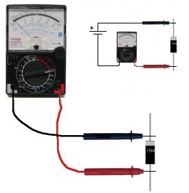
The diode is
REVERSE BIASED in the
diagram above and diodes not conduct.
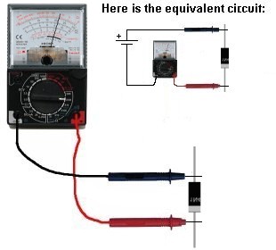
diagram above and it conducts TESTING A DIODE ON A DIGITAL METER
Testing a diode with a Digital Meter must be done on the "DIODE" setting as a digital meter does not deliver a current through the probes on some of the resistance settings and will not produce an accurate reading.
The best thing to do with a "suspect" diode is to replace it. This is because a diode
has a number of characteristics that cannot be tested with simple
equipment. Some diodes have a fast recovery for use in high frequency
circuits. They conduct very quickly and turn off very quickly so
the waveform is processed accurately and efficiently.
If the diode is replaced with an ordinary diode, it will heat up as does
not have the high-speed characteristic.
Other diodes have a low drop across them and if an ordinary is used, it
will heat up.
Most diodes fail by going: SHORT-CIRCUIT. This can be detected by
a low resistance (x1 or x10 Ohms range) in both directions.
A diode can also go OPEN CIRCUIT. To locate this fault, place an
identical diode across the diode being tested.
A leaky diode can be detected by a low reading in one direction and a
slight reading the other direction.
However this type of fault can only be detected when the circuit is
working. The output of the circuit will be low and sometimes the diode
heats up (more than normal).
A diode can go open under full load conditions and perform
intermittently.
Diodes come in pairs in surface-mount packages and 4 diodes can be found in
a bridge.
They are also available in pairs that look like a 3-leaded transistor.
The line on the end of the body of a diode indicates the cathode and you
cannot say "this is the positive lead." The correct way to
describe the leads is to say the "cathode lead." The other lead is
the anode. The cathode is defined as the electrode (or lead) through
which an electric current flows out of a device.
The following diagrams show different types of diodes:
POWER DIODES
To understand how a power diode works, we need to describe a few things.
This has NEVER been described before, so read carefully.
The 240v AC (called the "mains") consists of two wires, one is called the ACTIVE and the
other is NEUTRAL. Suppose you touch both wires. You will get a shock. The neutral is connected
to an earth wire (or rod driven into the ground or connected to a water
pipe) at the point where the electricity enters the premises
and you do not get a shock from the NEUTRAL.
But the voltage on the active is rising to +345v then goes to -345v at
the rate of 50 times per second (for a complete cycle).
345v is the peak voltage of 240v. You never get a 240v shock. (It is a
345v shock.)
In other words, if you touch the two wires at a particular instant, you
would get a POSITIVE 345v shock and at another instant you would get a
negative 345v shock. This is shown in the diagram below.
We now transfer this concept to the output of a transformer. The
diagram shows an AC waveform on the output of the secondary.
This voltage is rising 15v higher than the bottom lead then
it is 15v LOWER
than the bottom lead. The bottom lead is called "zero volts."
You have to say one lead or wire is not "rising and falling" as you
need a "reference" or starting-point" or "zero point" for
voltage measurements.
The diode only conducts when the voltage is "above zero"
(actually when it is 0.7v above zero) and does not
conduct (at all) when the voltage goes below zero.
This is shown on the output of the Power Diode. Only
the positive peaks or the positive parts of the waveform appear on the
output and this is called "pulsing DC." This is called
"half-wave" and is not used in a power supply. We have used it to
describe how the diode works. The electrolytics charge
during the peaks and deliver energy when the diode is not delivering
current. This is how the output becomes a steady DC voltage.
Power supplies use FULL WAVE rectification and the other half of the AC
waveform is delivered to the output (and fills in the "gaps") and appears as shown in "A."
ONE FAULTY DIODE
One diode in a bridge can go open (any of the 4 diodes
will produce the same effect) and produce an output voltage that can be
slightly lower than the original voltage. The actual "voltage-drop" will depend
on the current taken by the circuit and the ability of the transformer
to produce the required voltage and current during half-wave operation.
The voltage during each half cycle (when none of the diodes is
delivering any energy to the circuit) is maintained by the electrolytic and
its size (relative to the current taken by the
circuit) will determine the size of the ripple that will result when the diode
fails. The ripple will be 100 to 1,000 times greater after the failure
of a diode, depending on the value of the filter capacitor.
To locate the faulty diode, simply get a diode and place it across each of the diodes in the bridge
(in turn) when the circuit is working.
For a bridge rectifier, the ripple-frequency will be twice the mains
frequency and its ripple will be very small if the electrolytic is
the correct value. When a diode fails, the ripple-frequency will be
equal to mains-frequency and the amplitude will increase
considerably. You may even hear background hum from audio equipment.
If you cannot find a faulty diode, the filter capacitor will be at
fault. Turn off the equipment and connect an electrolytic across the
filter capacitor via jumper leads. Turn the power ON and see if the hum
has reduced.
A damper diode is a diode that detects a high voltage and SQUELCHES IT (reduces it - removes it). The signal that it squelches is a voltage that is in the opposite direction to the "supply voltage" and is produced by the collapsing of a magnetic field. Whenever a magnetic filed collapses, it produces a voltage in the winding that is opposite to the supply voltage and can be much higher. This is the principle of a flyback circuit or EHT circuit. The high voltage comes from the transformer.
The diode is placed so that the signal passes through it and less than 0.5v appears across it.
A damper diode can be placed across the coil of a relay, incorporated into a transistor or FET or placed across a winding of a flyback transformer to protect the driving transistor or FET.
It can also be called a "Reverse-Voltage Protection Diode," "Spike Suppression Diode," or "Voltage Clamp Diode."
The main characteristic of a Damper Diode is HIGH SPEED so it can detect the spike and absorb the energy.
It does not have to be a high-voltage diode as the high voltage in the circuit is being absorbed by the diode.
SILICON, GERMANIUM AND SCHOTTKY DIODES
When testing a diode with an analogue meter, you will get a low reading in one direction and a high (or NO READING) in the other direction. When reading in the LOW direction, the needle will swing nearly full scale and the reading is not a resistance-value but a reflection of the characteristic voltage drop across the junction of the diode. As we mentioned before, a resistance reading is really a voltage reading and the meter is measuring the voltage of the battery minus the voltage-drop across the diode.
Since Silicon, Germanium and Schottky Diodes have slightly different characteristic voltage drops across the junction, you will get a slightly different reading on the scale. This does not represent one diode being better than the other or capable of handling a higher current or any other feature.
The quickest, easiest and cheapest way to find, fix and solve a problem caused by a faulty diode is to replace it.
There is no piece of test equipment capable of testing a diode fully, and the circuit you are working on is actually the best piece of test equipment as it is identifying the fault UNDER LOAD.
Only very simple tests can be done with a multimeter and it is best to check a diode with an ANALOGUE MULTIMETER as it outputs a higher current though the diode and produces a more-reliable result.
A Digital meter can produce false readings as it does not apply enough current to activate the junction.
Fortunately almost every digital multimeter has a diode test mode. Using this, a silicon diode should read a voltage drop between 0.5v to 0.8v in the forward direction and open in the reverse direction. For a germanium diode, the reading will be lower, around 0.2v - 0.4v in the forward direction. A bad diode will read zero volts in both directions.
REPLACING A DIODE
It is
always best to replace a diode with the same type but quite often this is
not possible. Many diodes have unusual markings or colours or "in-house"
letters.
This is only a general guide because many diodes have special features,
especially when used in high-frequency circuits.
However if you are desperate to get a piece of equipment working, here
are the steps:
Determine if the diode is a signal diode, power diode, or zener
diode.
For a signal diode, try 1N4148.
For a power diode (1 amp) try 1N4004. (for up to 400v)
For a power diode (3 amp) try 1N5404. (for up to 400v)
For a high-speed diode, try UF4004 (for up to 400v)
If you put an ordinary diode in a high-speed application, it will get very hot very quickly.
To replace an unknown zener diode, start with a low voltage such as 6v2 and see if the circuit works.
The size of a diode and the thickness of the leads will give an idea of the current-capability of the diode.
Keep the leads short as the PC board acts as a heat-sink.
You can also add fins to the leads to keep the diode cool.
DIODE BRIDGE
The rating of a diode depends on the way it is connected to a printed circuit board via the two leads. It does not matter if the diode is rated a 1 amp or 3 amp, if it is connected "in the air" it will dissipate less than 1 watt and since a diode has a characteristic voltage drop across it when full current is flowing, it will only pass less than 1 amp.
If we take a 1 watt resistor, it will only dissipate 1 watt when it is connected directly to the tracks of a PC board. These tracks are enormously important as two 330R resistors in series in a project I was fixing had one resistor burn out. Now this is theoretically impossible when they are passing the same current. But after a lot of investigation the failed resistor had narrower and shorter tracks.
A 1 amp diode may be the same size but when connected "in the air" it will dissipate much less than 1 watt.
Here we see 2 projects from YouTube, claiming to be a 3 amp bridge. These bridges will have about 1 amp capability. Even though each diode will be active for only 50% of each cycle, the first image uses 1amp diodes and the maximum you can expect them to pass is 1 amp for each half cycle. This will create a lot of heat in the leads and the heat will not be able to go anywhere because another diode connects to the lead. On top of this the voltage drop of each diode will be greater than 1.1v when 1 amp is flowing.
A 1 amp diode is really only suitable for 700mA max. As the current increases from 700mA to 1 amp, the temperature rises enormously because the wattage dissipated rises as the square of the current P=I2R
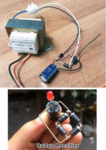
The image above shows 3 amp diodes in a bridge. But the
limiting factor is the heat generated. If you cannot hold your fingers
on a component, it is getting too hot. This bridge is limited to 1.5 amp
due to the heat it will generate.
If you maintain
more than 1.5 amp, I am sure the solder will soften and the diodes will
fall off!
LIGHT
EMITTING DIODES (LEDs)
Light Emitting Diodes (LEDs) are diodes that produce light when current
flows from anode to cathode. The LED does not emit light when it is
revered-biased. It is used as a low current indicator in many
types of consumer and industrial equipment, such as monitors, TV’s,
printers, hi-fi systems, machinery and control panels.
The light produced by a LED can be visible, such as red, green, yellow
or white. It can also be invisible and these LEDs are called Infrared
LEDs. They are used in remote controls and to see if they are working,
you need to point a digital camera at the LED and view the picture on
the camera screen.
An LED needs about 2v - 3.6v across its leads to make it emit light, but this
voltage must be exact for the type and colour of the LED. The
simplest way to deliver the exact voltage is to have a supply that is
higher than needed and include a voltage-dropping resistor. The value of
the resistor must be selected so the current is between 2mA and 25mA.
The cathode of the LED is identified by a flat on the side of the LED. The
life expectancy of a LED is about 100,000 hours. LEDs rarely fail but
they are very sensitive to heat and they must be soldered and
de-soldered quickly. They are one of the most heat-sensitive components.
Light emitting diodes cannot be tested with most multimeters because the
characteristic voltage across them is higher than the voltage of the
battery in the meter.
However a simple tester can be made by joining 3 cells together with a
220R resistor and 2 alligator clips:
LED TESTER
is a very simple project from Talking Electronics that tests LEDs and
diodes and continuity. It is one of the most useful projects to add to
your TEST EQUIPMENT.
Connect the clips to a LED and it will illuminate in only one direction.
FLASHING LEDs
The oscillator inside the case is so small, it cannot be seen.
When the incoming voltage is
positive at the top, the left zener provides 18v limit (and the other
zener produces a drop of 0.6v). This allows the right zener to
pass current just like a normal diode. The output is 17v4. The same with the
other half-cycle. 
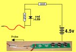
LED TESTER
The colour of the LED will determine the voltage across it. You can
measure this voltage if you want to match two or more LEDs for identical
operation.
Red LEDs are generally 1.7v to 1.9v. - depending on the quality such as
"high-bright"
Green LEDs are 1.9v to 2.3v.
Orange LEDs are about 2.3v and
White LEDs and IR LEDs are about 3.3v to 3.6v.
The illumination produced by a LED is determined by the quality of the
crystal. It is the crystal that produces the colour and you need to
replace a LED with the same quality to achieve the same illumination.
Never connect a LED across a battery (such as 6v or 9v), as it will be
instantly damaged. You must have a resistor in series with the LED to
limit the current.
The LED TESTER also identifies a very unusual property of some LEDS.
Some of the powerful LEDs illuminate in a display but fail to illuminate
when tested with LED Tester. When they are replaced, the current
take by the display reduces considerably. It seems the faulty LEDs will
illuminate but take excess current.
An ordinary LED can be flashed by using one of the following circuits.
This allows a very bright LED to flash and give a special effect. The
secret is to use a flashing LED to prove the on/off operation.
The flashing LED can be 3mm 5mm or SURFACE MOUNT.
These LEDs have an inbuilt resistor so the applied voltage can be as low
as 3v and up to 7v.
You can use them to illuminate a brighter LED with the following single
transistor circuits. The second circuit operates on 3v from a coin cell. It
is only suitable for red LEDs.
Here is an 0805 flashing LED. 
These devices are the same price as an ordinary surface mount LED and need
no other components. They will operate from 3v to 7v and have an internal
dropper-resistor.
The flash rate is about 1- 2 Hz and are available in red, green, blue and
white.
You can also get 3mm LEDs red, green, blue flashing and random flashing and
flickering orange LEDs. These are all available on eBay. Most of them work
on 3v to 7v and take about 10mA to 20mA. You can connect a piezo diaphragm
across them and listen to the oscillator "clocking."
To find out the maximum supply voltage, connect the LED to a variable supply
and put a milliamp meter in the positive line. Read the current (as the
voltage is increased) and when it reaches 20mA to 25mA you have found the
maximum supply voltage.
ZENER DIODES
All diodes are Zener diodes. For instance a 1N4148 is a 120v zener diode
as this is its reverse breakdown voltage.
And a zener diode can be used
as an ordinary diode in a circuit with a voltage that is below the zener value.
For instance, 20v zener diodes can be used in a 12v power supply as the
voltage never reaches 20v, and the zener characteristic is never
reached.
Most diodes have a reverse breakdown voltage above 100v, while most
zeners are below 70v. A 24v zener can be created by using two 12v
zeners in series and a normal diode has a characteristic voltage of
0.7v. This can be used to increase the voltage of a zener diode by 0.7v.
See the diagram above. It uses 3 ordinary diodes to increase the output
voltage of a 3-terminal regulator by 2.1v.
To tests a zener diode you need a power supply about 10v higher than the
zener of the diode. Connect the zener across the
supply with a 1k to 4k7 resistor and measure the voltage across the
diode. If it measures less than 1v, reverse the zener.
If the reading is high or low in both directions, the zener is damaged.
Here is a zener diode tester. The circuit will test up to 56v zeners.
ZENER DIODE TESTER
TRANSFORMERLESS POWER SUPPLY
Here's a circuit
that uses zener diodes in a power supply to show how they work.
This clever design uses 4 diodes in a bridge to produce a fixed voltage
power supply capable of supplying 35mA.
If we put 2 zener diodes in a bridge with two ordinary power diodes, the
bridge will break-down at the voltage of the zener. This is what we have
done. If we use 18v zeners, the output will be 17v4.
![]()
SUPPLY USING ZENER DIODES
You cannot use this type of bridge in a normal power supply as the zener
diode will "short" when the input voltage reaches the zener value. The
concept only works in the circuit above.
VOLTAGE REGULATORS
A Voltage Regulator takes a high input voltage and delivers a fixed
output voltage.
Providing the input voltage is 4v above the output voltage, the
regulator will deliver a fixed output voltage with almost no ripple.
Voltage regulators are also called "3-TERMINAL REGULATORS" or "REGULATOR
IC's" - although this name is not generally used.
In most cases, a voltage regulator gets quite hot and for this reason it
has a high failure-rate.
If a regulator is not getting hot (or warm) it has either failed or the
circuit is not operating.
A regulator can only decrease the voltage. It cannot increase the
current. This means the current being supplied to a circuit must also be
available from the circuit supplying the regulator.
All regulators have different pin-outs, so you need to find the input
pin and output pin and make sure the voltage-difference is at least 4v.
Some regulators will work with a difference as low as 1v, so you need to
read the specifications for the type you are servicing.
Some regulators are called “negative voltage regulators” and the input
voltage will be negative and the output will be negative.
You need to test a voltage regulator with the power "ON".
Make sure you
do not allow the probes to short any of the pins together as this will destroy the regulator
or the circuit being supplied.
With the power turned off or the regulator removed from the circuit, you
can test it with a multimeter set to resistance to see if it is ok. If
any resistance readings are very low or zero ohms, the regulator is
damaged.
There is a new module on the market called a DC-DC CONVERTER. I say "new" because they have come down in price to a point where they sell for less than the cost of buying the components separately.
And they solve a lot of problems.
Suppose you have a power supply for an amplifier or other device and need to increase the voltage slightly to get better performance.
This is the perfect application for a DC-DC CONVERTER. The converter shown below is a BOOST CONVERTER and will increase say 12v to produce an output of 15v.
It is also ideal for converting almost any voltage from say 5v to 15v to deliver an output voltage 26.5v to a Capacitor Discharge Unit.
It is also capable of handling currents up to 3 amp. But it does not have an input protection diode and will "blow up" if the reverse voltage is applied to the input.
This happened to a number of our customers and when you are installing a new module that connects to a power supply, it is best to put a 10R to 47R in series with one of the input leads. Turn the supply On and OFF very quickly and feel the resistor. If it is not getting hot, try for longer. If it gets hot, see if the load is taking a high current. Once you are certain it is connected correctly, remove the resistor and adjust the 10-turn pot with a screwdriver in the ANTI-CLOCKWISE direction to INCREASE the voltage. Monitor the output voltage and make sure it does not exceed the allowable input voltage of the
device you are powering.
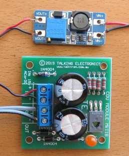
TRANSFORMERS
All transformers and coils are tested the same way. This includes
chokes, coils, inductors, yokes, power transformers, EHT transformers (flyback
transformers), switch mode transformers, isolation transformers, IF
transformers, baluns, and any device that has turns of wire around a
former. All these devices can go faulty.
The coating on the wire is called insulation or "enamel" and this can crack or
become overheated or damaged due to vibration or movement. When two
turns touch each other, a very interesting thing happens.
The winding becomes two separate windings.
![]()
We will take the case of a single winding such as a coil. This is shown
in the first diagram above and the winding is wound across a
former (a former is a bobbin or plastic molding or something to hold the
winding) and back again, making two layers. The bottom and top layers touch
at the point shown in the diagram and the current that originally passed
though A, B, C, D now passes though A & D.
Winding B C becomes a
separate winding as shown in the second diagram.
In other words the coil becomes a TRANSFORMER with a SHORT CIRCUIT on
the secondary winding as shown in the third diagram.
When the output wires of a transformer are
shorted together, it delivers a very high current because you have created a SHORT-CIRCUIT. This short-circuit causes the transformer
to get very hot.
That’s exactly what happens when any coil or transformer gets a “shorted
turn.”
The shorted turns can be a single turn or many turns.
It is not possible to measure a fault like this with a multimeter as you don’t
know the exact resistance of a working coil or
winding and the resistance of a faulty winding
may be only 0.001 ohms less.
However when a transformer or coil is measured with an inductance meter,
an oscillating voltage (or spike) is delivered
into the core as magnetic flux,
then the magnetic flux collapses and passes the energy into the winding
to produce a waveform. The inductance meter reads this and
produces a value of inductance in Henry (or milliHenry or microHenry.)
This is done with the transformer removed from the circuit and this can
be a very difficult thing to do, as most transformers have a number of
connections.
If the coil or transformer has a shorted turn, the energy from the
magnetic flux will pass into the turns that are shorted and
produce a current. Almost no voltage will be detected from winding.
The reading from the inductance meter will be low or very low and you
have to work out if it is correct.
However there is one major problem with measuring a faulty transformer
or coil.
It may only become faulty when power is applied.
The voltage between the turns may be sparking or jumping a gap and
creating a problem. A tester is not going to find this fault.
Secondly, an inductance meter may produce a
reading but you do not know if the reading is correct.
An improved tester is a RING TESTER.
The circuit for a ring tester can be found here:
http://www.flippers.com/pdfs/k7205.pdf
It sends a pulse to the coil and counts the number of returning pulses
or "rings."
A faulty coil (or winding) may return one pulse but nearly all the
energy will be passed to the shorted turns and you will be able to see
this on the scale. You will only get one or two return pulses, whereas a
good winding will return more pulses.
One way to detect a faulty power transformer is to connect it to the
supply and feel the temperature-rise (when nothing is connected to the
secondary).
It should NOT get hot.
Detecting shorted turns is not easy to diagnose as you really need
another identical component to compare the results.
Most transformers get very hot when a shorted turn has developed.
It may deliver a voltage but the heat generated and a
smell from the transformer will indicate a fault.
ISOLATION
TRANSFORMER
An isolation transformer is a piece of Test Equipment that
provides "Mains Voltage" but the voltage is "floating." You will still
get a shock if you touch the two output leads, but it has a special use
when testing unknown equipment.
Many electrical appliances are fully insulated and only have two leads
connected to the mains.
When you take these appliances apart, you do not know which end of say a
heating element is connected to the "live" (active) side of the
mains and which end connects to the neutral.
I am not suggesting you carry out the following tests, but they are
described to show how an isolation transformer works.
If you touch a soldering iron on the "live" (active) end of the heating
element it will create a short-circuit.
However when the appliance is connected to the mains via an isolation
transformer, you can touch an earthed soldering iron on either end of
the heater as
both leads from the isolation transformer are "floating."
Note:
As soon as you earth one lead of the output an isolation transformer, the other
lead becomes "active."
You can make your own Isolation Transformer by connecting two identical
transformers "back-to-back."
The following diagram shows how this is done:
![]()
![]()
You can use any transformers providing the primary and secondary
voltages are the same. The current capability of the secondary winding
does not matter. However if you want a supply that has almost the same
voltage as your "Mains," you need two transformers with the same
voltages.
This handy isolation transformer will provide you with "Mains Voltage"
but with a limited current.
In other words it will have a limited capability to supply "wattage." If
you are using two 15VA transformers, you will only be able to test an
appliance rated at 15 watts.
This has some advantages and some disadvantages.
If you are working on a project, and a short-circuit occurs, the damage
will be limited to 15 watts.
If you are using two transformers with different VA ratings, the lower
rating will be the capability of the combination.
If the secondaries are not equal, you will get a higher or lower "Mains
Voltage."
If you get two transformers from TVs or Monitors, with a rating on the compliance
plate of 45 watts, or 90 watts, you can assume the transformers are
capable of delivering this wattage and making an isolation transformer
will enable you to test similar items with the safety of being isolated
from the mains.
Colin Mitchell designs a lot of "LED lighting lamps" that are connected
directly to the mains. He always works with an isolating transformer,
just to be safe. Working on exposed "mains" devices is extremely
nerve-wracking and you have to be very careful.
The isolation transformer will prevent a BIG EXPLOSION.
DETERMINING THE SPECS OF A TRANSFORMER
Suppose you have a "mains transformer" with unknown output voltages and
unknown current capability.
You must be sure it is a mains transformer designed for operation on 50Hz
or 60Hz. Switch-Mode transformers operate at frequencies 40kHz and higher
and are not covered in this discussion.
To be on the safe-side, connect the unknown transformer to the output of
your isolating transformer.
Since the transformer will take almost no current when not loaded, the
output voltages it produces will be fairly accurate. Measure the input
AC voltage and output AC voltage.
If the transformer has loaded your isolating transformer it will be
faulty.
Mains transformers are approx 15VA for 500gm, 30VA for 1kgm
50VA for 2kgm and and 100VA for 2.5kgm.
VA stands for Volts-Amps and is similar to saying watts. Watts is used
for DC circuits, while VA refers to AC circuits.
Once you have the weight of the transformer and the output voltage, you
can work out the current capability of the secondary.
For transformers up to 30vA, the output voltage on no-load is 30% higher
than the final "loaded voltage."
This is due to the poor regulation of these small devices.
If the transformer is 15VA and the output voltage is 15v AC, the current
will be 1 amp AC.
You can check the "quality" of the transformer, (the regulation) by
fully loading the output and measuring the final voltage. If the
transformer has a number of secondaries, the VA rating must be divided
between all the windings.
240v to 110v ISOLATION TRANSFORMER
Here's how to create a 110v isolating transformer:
Find a 240v:12v transformer.
Now find a transformer that has two secondary windings, such as
240v:12v+12v.
![]()
Connect the two transformers as shown in the circuit above. If the
output is zero, connect ONE of the 12v windings of the second
transformer around the other way.
110v to 240v ISOLATION TRANSFORMER
![]()
A 110v to 240v isolation transformer can be created by connecting 3
identical transformers as shown in the diagram above. If the
output is zero, connect one of the outputs around the other way.
TRANSFORMER RATINGS
Question from a reader:
I have a 28v - 0 - 28v transformer @3amps. Does this mean each side is
1.5 amps?
The transformer is called CENTRE TAPPED and is shown in figures B and C.
It is designed to be connected to two diodes so each winding takes it in
turn to deliver the current as shown in diagram C and the output will be
28v AC at 3 amps.
Each winding is delivering up to 3 amps for half-cycle and nothing for
the next half-cycle.
The 28v and 3 amp are both AC values.
If you connect across both outside wires, the output will be 56v at 1.5
amp.
This is because the transformer has a VA rating of 28 x 3 = 84VA. This
is very similar to the term "watts."
When the 28v AC is rectified and smoothed, it becomes 28 x 1.4 =
39v (minus 0.6v across the diode) and since the transformer has a rating
of 84 VA, the current must be reduced to 84/39 = 2.1 amps to maintain
the VA rating. So, you will only get 2.1 amps DC and 39v DC from the two
diodes.
Some transformers are specified as say: 12v - 0 - 12v, but the wiring
diagram is shown as "A." This transformer should be specified as
12v + 12v as the secondaries are separate.
12v - 0 - 12v means the two secondary windings are NOT separate.
It does not make any difference to the output voltage and current, if
the windings are separate or joined. The only difference is 12v +12v can
be turned into two separate 12v outputs.
If you do not know the output current for a particular transformer, go
to the website of electronic parts suppliers and compare the weight of
your transformer with others. This will give you a VA rating and you can
work out the current, once you know the output voltage.
Note: the output current finishes up ONLY 60% of the rating on the
transformer tag because the rating is an AC RATING.
With 2 separate secondaries, you can parallel the outputs to get double
the current, but don't forget 12v + 12v @ 3amp means 12v in
parallel with 12v will provide 2amp DC and the DC voltage will be about
17v.
CURRENT TRANSFORMER
A Current Transformer is really
an ordinary transformer.
All transformers produce a CURRENT output and a VOLTAGE output.
If you put an ammeter across the secondary, the current will increase
through the meter when the primary voltage is increased.
This is because the output voltage will increase and this voltage will
allow a higher current to flow.
Because the voltage of say the "240v AC" is always 240v but the current can increase from say 1 amp to nearly 15 amps, depending what appliance is connected. So it is pointless measuring voltage.
A Current Transformer is a step-up transformer. When we say step-up and step-down, we are referring to the voltage - comparing the primary voltage to the secondary voltage. (Most transformers on the "mains" are step-down transformers and are used as power supplies to laptops, phone chargers etc.) Even a welding transformer is a step-down device and produces about 20v to 70v, while the current can be as high as 100 amps. This current is higher than the mains will deliver and is needed to melt the metal at the point of contact of the probe and the item being welded.
A Current Transformer is a step-up transformer. The primary consists of a single turn (or maybe 2 - 5 turns) and the secondary has 100 turns (or more).
This means the voltage seen by the primary will be increased 100 times and appear as anything from a few hundred millivolts to a few volts, depending on the quality of the coupling. (the magnetic coupling between the wire through the centre of the core, the quality of the core to transfer this magnetic flux to the secondary turns.) This voltage is then passed to a low value resistor, where the voltage is reduced to a level that suits the detection circuit and the resulting millivolts is interpreted as current in the wire being tested.
Recapping:
The reading on the secondary has no relation to the current in the primary. We need to add a LOAD RESISTOR and create a table before we can use the transformer.
There is no such thing as a CURRENT TRANSFORMER. It is really an INSTRUMENT TRANSFORMER and the scale has been marked in units of CURRENT after measurements have been made. (INSTRUMENT TRANSFORMER means it is a device that helps us to produce a connection between current flowing through a wire and a reading on a meter or display).
If we connect a load to the secondary, (say an ammeter), it will produce a reading that increases when the current through the single primary turn is increased. That's because the ammeter is a LOAD. But the reading is meaningless until be calibrate the scale.
Now, lets look at the primary.
A wire (or cable) through the centre of the core is counted as one turn. If the turn is wrapped around the core, the coupling will be improved, but if we always use a straight wire, it does not matter where it is positioned inside the centre of the core.
It does not matter if the magnetic interaction of the flux from the wire is good or bad, we just have to keep to the same way of using the transformer.
The calibration can be done with any poor coupling and the result will be accurate for all future readings.
If a low-value resistor is placed across the secondary, the voltage across this resistor will increase and also the current through it will increase. But we are not going to measure the current through the resistor. We are going to measure the voltage across the resistor and by taking lots of reading we will finish up with a scale or table and this is called CALIBRATION. The results will be equated to the current flowing through the primary wire (primary turn).
A clamp meter uses a current transformer and the jaws must be closed completely and cleanly for the flux to flow around the core and produce a reading in the secondary.
Dirt in the jaws will reduce the reading considerably.
You cannot measure the current in a "power cord" because it contains both the active and neutral wires.
Even though the current is a maximum in both conductors at the same time, the current is flowing in two different directions and the magnetic flux produced by one conductor is clockwise and the other is anticlockwise and they are cancelled by each other.
![]()
Identifying ONE TURN.
The quality (the coupling) of a single STRAIGHT wire
through the centre of a core is very poor
but if all readings are taken with this amount
of coupling, the readings will be accurate, as the
calibrations have been done with this arrangement.
COMMON MODE TRANSFORMER -really COMMON MODE CHOKE

This component is very small but it has a big effect
because the magnetic flux produced by one winding is in the opposite
direction to the flux produced by the other winding. This means there is
a resulting almost zero flux in the core.
In the lower image, the red winding and "copper" winding are wound
around the core and back to the starting point.
This means the two red wires are on the left.
Now, to work out which way the flux is being created in the core you
have to see which way the turns are wound and also understand the
direction of the current because one winding is in the positive lead and
the other is in the negative lead.
When you have zero final flux, the windings are correct.
Only two things can go wrong with this component. Either a wire breaks
at the termination or two turns burn together due to the high voltage.
Suppose a pulse or spike appears on the positive line. This will create
magnetic flux.
This magnetic flux will pass to the negative winding and try to produce
a voltage in it. Buy because there is a current flowing through the
negative winding, the winding will appear a shorted-turn or at least a
turn that will absorb the flux. This means the spike will not get
through the choke. It will not come out the positive lead and not appear
in the negative lead.
In fact this small component will have a very big effect on removing
spikes due to the "shorted-turn" effect of the other winding.
OPTO Components Including LDRs, Photo Electric Cells (PE
Cells) Photo Transistors, IR transistors and solar cells.
All the components we are going to cover respond to light, sun-light,
room light, LED light, torch light or Infra Red light.
Most of these components have 2 leads and the simplest way to test them
is with an analogue multimeter as the meter has an inbuilt 1.5v or 3v
supply to operate the pointer on the meter when the leads are connected
to a component and the scale is set to the highest ohms range.
The first thing you do is add alligator clips so your hands do not
change the reading on the scale and place the component in front of a
lamp, light or the sun.
The needle should not move when in darkness and move almost fully across
the scale when in bright light.
This proves the component is responding to the light.
If the component does not respond or has 3 leads or a dark body, you
will have to reverse the leads and only responds to sun-light.
Put your hand in front of the component to see the difference between
full light and random light to see how sensitive the device is.
This gives you some idea of its SENSITIVITY.
If it only works around one way, it is transistor device - PHOTO
TRANSISTOR - and can be a normal Photo Transistor that picks up room
light or an IR (Infra Red) transistor that picks up Infra-Red
illumination.
A solar cell produces a voltage and current when exposed to light and
you can use the 10 volt scale and the 500mA scale to determine these
values. Using the 500mA scale across the solar cell (pr solar panel)
does not do any damage and gives you some idea of the current it will
produce when in full sunlight.
You can also test LEDs with the high ohms scale or the microamps scale
and see the very small voltage and current it produces.
Once the component moves the pointer on a multimeter, you can put it in
a circuit and find out its sensitivity.
All we are doing at the moment is sorting out components that are light
detecting.
OPTO ISOLATORS and OPTO COUPLERS
Opto Isolators and Opto
Couplers are the same thing. A common opto-coupler is 4N35. It is
used to
allow two circuits to exchange signals yet remain electrically isolated.
The signal is applied to the LED, which shines on a silicon NPN
photo-transistor in the IC.
The light is proportional to the signal, so the signal is transferred to the photo
transistor to turn it on a proportional amount. Opto-couplers can have
Light Activated SCR's, photodiodes, TRIAC's and other semiconductor
devices
as an output. The 4N35 opto-coupler schematic is shown below:
An opto-Coupler using a TRIAC
Note: the pinout is different to 4N35
TESTING AN OPTO COUPLER
Most multimeters cannot test the LED on the input of
an opto-coupler because the ohms range does not have a voltage high
enough to activate the LED with at least 2mA.
You need to set-up the test-circuit shown above with a 1k resistor on the
input and 1k5 on the output. When the 1k is connected to 12v, the output
LED will illuminate.
The opto-coupler should be removed from circuit to perform this test.
Transistors are solid-state devices and although they operate completely differently to a diode, they appear as two back-to-back diodes when tested.
There are basically 2 types of transistor NPN and PNP.
A transistor is sometimes referred to as BJT (Bi-polar Junction Transistor) to distinguish it from other types of transistor such as Field Effect transistor, Programmable Unijunction Transistor and others.
In the following diagram, two diodes are connected together and although the construction of a transistor is more complex, we see the transistor as two diodes when testing it.
A TRANSISTOR APPEARS AS TWO DIODES
WHEN TESTING IT
All transistors have three leads. Base (b), Collector (c), and Emitter (e).
For an NPN transistor, the arrow on the emitter points away from the
base.
It is fortunate that the arrow on both symbols points in the direction of
the flow of current (Conventional Current) and this makes it easy to describe testing methods
using our simplified set of instructions. The symbols have been drawn
exactly as they appear on a circuit diagram.
All transistors are the same but we talk about digital and
analogue transistors. There is no difference between the two.
The difference is the circuit. And the only other slight difference
between transistors is the fact that some have inbuilt diodes and
resistors to simplify the rest of the circuit.
All transistors work the same way. The only difference is the amount of
amplification they provide, the current and voltage they can withstand
and the speed at which they work. For simple testing purposes, they are
all the same.
NPN transistors are the most common and for an NPN transistor, the
following applies.
(the opposite applies for PNP)
To test a transistor, there is
one thing
you have to know:
As the voltage is increased on the base, nothing happens until the voltage reaches 0.55v. At this point a very small current flows through the collector-emitter leads. As the voltage is increased, the current-flow increases. At about 0.75v, the current-flow is a MAXIMUM. (can be as high as 0.9v). That's how it works. A transistor also needs current to flow into the base to perform this amplifying function and this is the one feature that separates an ordinary transistor from a FET.
If the voltage on the base is 0v, then instantly goes to 0.75v, the transistor initially passes NO current, then FULL current. The transistor is said to be working in its two states: OFF then ON (sometimes called: "cut-off" and "saturation"). These are called digital states and the transistor is said to be a DIGITAL TRANSISTOR or a SWITCHING TRANSISTOR , working in DIGITAL MODE.
If the base is delivered 0.5v, then slowly rises to 0.75v and slowly to 0.65v, then 0.7v, then 0.56v etc, the transistor is said to be working in ANALOGUE MODE and the transistor is an ANALOGUE TRANSISTOR.
Since a transistor is capable of amplifying a signal, it is said to be an active device. Components such as resistors, capacitors, inductors and diodes are not able to amplify and are therefore known as passive components.
In the following tests, use your finger to provide the TURN ON voltage for the base (this is 0.55v to 0.7v) and as you press harder, more current flows into the base and thus more current flows through the collector-emitter terminals. As more current flows, the needle of the multimeter moves UP-SCALE.
TESTING A TRANSISTOR -
DETERMINING THE GAIN OF A TRANSISTOR
A transistor is used in a circuit because it has a GAIN. In other words it has an AMPLIFICATION FACTOR. In other words the current on or through the output section of the transistor is higher than the current entering the stage (or transistor).
The gain (the Amplification factor) of a transistor can be between 2 and 1,000.
But measuring this value is very difficult.
And the reading you get is very inaccurate.
Here are 4 different types of instruments (test gear) to measure the gain of a transistor:
A $190 piece of equipment that can show a number of parameters of a transistor.
A $10.00 piece of equipment that tests transistors, inductors, capacitors, resistors
A dedicated tester for transistors
The item above is a normal "standard" Digital Multimeter. It can be used to determine the gain of the transistor if you follow the steps below.
I must
admit I have all these pieces of test gear and I have never used any of
them. They were supplied as samples from suppliers.
The gain of a transistor when testing it on a tester above may show a
value of 120.
But this is when the current through the device "under test" is very
small. It may be 1mA. But when the transistor is placed in a circuit and
10mA flows through the collector-emitter section, the gain will drop to
say 70. And if the current is 100mA, the gain may drop to 40. And the
components around the transistor may reduce the gain to 30 or less.
That means testing it out-of-circuit does not tell you anything.
The only way to test a transistor is this:
In most cases we need to test a transistor when it is driving a relay or
globe or solenoid.
We need to know if the components and the driving current is sufficient
when all the transistors in a batch are used in a product.
It's simple. Cut the track on the base and insert a milliamp meter.
Measure the current.
Now connect a resistor from the power rail to the meter (remove one lead
so this can be done accurately) so that the same current flows into the
base. Suppose the value of this resistor is 10k. Now use a 22k resistor
and see if the relay or lamp or solenoid works the same as before. If
not, use 15k.
We are attempting to work out the tolerance between the circuit working
and not working. You should have an allowance of at least 50%. In other
words, the circuit must work with a value of 15k. If not, replace the
10k resistor on the printed circuit board with 8k2 or lower.
The Gain of a
Transistor:
All the pieces of Test Gear above use the same procedure and
the same formula.
They measure the current into the base (normally one-tenth of a
milliamp) and at the same time measure the current through a resistor
connected to the collector.
This is called the DC current gain and is the same as you will obtain
from a circuit operating a relay or globe.
If the circuit is passing a signal, the transistor is oscillating and
the current through it is increasing and decreasing during each cycle.
As the frequency of the the circuit increases, the ability for a
transistor to provide an amplification-factor DECREASES. As soon as this
decrease reaches a gain of say 2, the maximum frequency for the
transistor is determined. But what is the point of having a circuit that
only has a gain of 2 or 3 !!!!
That's why the value of gain is such an unknown value.
Working
out the Gain of a Transistor
You can work out the
Basically you are using the circuit described above (with the relay) and it will look like this:
![]()
The current into the base of the transistor is adjusted so that it is
0.1mA and the value of the red load resistor is adjusted so the current
is 10mA. If the voltage across the transistor is less and 0.5v, the
transistor is fully turned ON and the gain is 100 or greater. If you
decrease the value of the red resistor to half the previous value and
the voltage across the transistor remains less than 0.5v, the gain will
be 200.
The voltage of the supply for the test circuit above should be 5v to
12v,
We are not going into this test in any more detail because the numerical
value for the gain of a transistor is not very important. All you
need to know is the success of the circuit and the fact that all the
transistors in a batch will work perfectly.
You can use the previous test to see if the "drive current" you are
supplying to the transistor in the project you are testing is sufficient
for all the transistors in a batch.
The following discussion detects the C, B E leads of a transistor and
detects if the junctions are no damaged. It does not test the
"quality" of a transistor or the current it will deliver or the maximum
voltage it will operate at. These are all things you have to get from a
data sheet.
TESTING A TRANSISTOR ON A DIGITAL METER
Testing a transistor with a Digital Meter must be done on the
"DIODE" setting as a digital meter does not deliver a current through
the probes on some of the resistance settings and will not produce an
accurate reading.
The "DIODE" setting must be used for diodes and transistors.
It should also be called a "TRANSISTOR" setting.
TESTING AN
unknown TRANSISTOR
The first thing you may
want to do is test an unknown transistor for COLLECTOR, BASE AND
EMITTER. You also want to perform a test to find out if it is NPN or PNP.
That's what this test will provide.
You need a cheap multimeter called an ANALOGUE METER - a
multimeter with a scale and pointer (needle).
It will measure resistance values (normally used to test
resistors) - (you can also test other components) and Voltage
and Current. We use the resistance settings. It may have ranges
such as "x10" "x100" "x1k" "x10"
Look at the resistance scale on the meter. It will be the top
scale.
The scale starts at zero on the right and the high values are on
the left. This is opposite to all the other scales.
When the two probes are touched together, the needle swings FULL
SCALE and reads "ZERO." Adjust the pot on the side of the meter
to make the pointer read exactly zero.
How to read: "x10" "x100"
"x1k" "x10"
Up-scale from the zero mark is "1"
When the needle swings to this position on the "x10"
setting, the value is 10 ohms.
When the needle swings to "1" on the "x100" setting, the
value is 100 ohms.
When the needle swings to "1" on the "x1k" setting, the
value is 1,000 ohms = 1k.
When the needle swings to
"1" on the "x10k" setting, the value is 10,000 ohms =
10k.
Use this to work out all the other values on the scale.
Resistance values get very close-together (and very inaccurate)
at the high end of the scale. [This is just a point to note and
does not affect testing a transistor.]
Step 1 - FINDING THE BASE
and determining NPN or PNP
Get an
unknown transistor and test it with a multimeter set to
"x10"
Try the 6 combinations and when you have the black probe on
a pin and the red probe touches the other pins and the meter
swings nearly full scale, you have an NPN transistor. The
black probe is BASE
If the red probe touches a pin and the black probe produces a
swing on the other two pins, you have a PNP transistor.
The red probe is BASE
If the needle swings FULL SCALE or if it swings for more than 2
readings, the transistor is FAULTY.
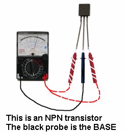
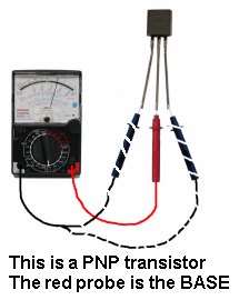
Step 2 - FINDING THE
COLLECTOR and EMITTER
Set the meter to
"x10k."
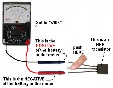
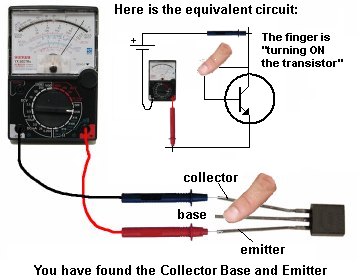
For a PNP transistor, set the meter to "x10k" place the leads on the transistor and when you press hard on the two leads shown in the diagram below, the needle will
swing almost full scale.
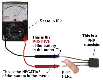
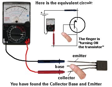
SIMPLEST
TRANSISTOR TESTER
The transistor will be NPN or PNP and the leads will be identified:
The leads of some transistors will need to be bent so the pins are in the same positions as shown in the diagrams. This helps you see how the transistor is being turned on. This works with NPN, PNP transistors and Darlington transistors.
HEATSINKING
This draws heat away, allowing it to handle more current. Low-power signal transistors do not normally require heat sinking. Some transistors have a metal body or fin to connect to a larger heatsink. If the transistor is connected to a heatsink with a mica sheet (mica washer), it can be damaged or cracked and create a short-circuit. (See Testing Mica Washers). Or a small piece of metal may be puncturing the mica. Sometimes white compound called Heatsink Compound is used to conduct heat through the mica. This is very important as mica is a very poor conductor of heat and the compound is needed to provide maximum thermal conduction.
TRANSISTOR FAILURE
Transistor can fail in a number of ways. They have forward and reverse voltage ratings and once these are exceeded, the transistor will ZENER or conduct and may fail. In some cases a high voltage will "puncture" the transistor and it will fail instantly. In fact it will fail much faster via a voltage-spike than a current overload.
It may fail with a "short" between any leads, with a collector-emitter short being the most common. However failures will also create shorts between all three leads.
A shorted transistor will allow a large current to flow, and cause other components to heat up.
Transistors can also develop an open circuit between base and collector, base and emitter or collector and emitter.
The first step in identifying a faulty transistor is to check for signs of overheating. It may appear to be burnt, melted or exploded. When the equipment is switched off, you can touch the transistor to see if it feels unusually hot. The amount of heat you feel should be proportional to the size of the transistor's heat sink. If the transistor has no heat sink, yet is very hot, you can suspect a problem.
DO NOT TOUCH A TRANSISTOR IF IT IS PART OF A CIRCUIT THAT CARRIES 240VAC. Always switch off the equipment before touching any components.
TRANSISTOR REPLACEMENT
If you can't get an exact replacement, refer to a transistor substitution guide to identify a near equivalent.
The important parameters are:
- Voltage
- Current
- Wattage
- Maximum frequency of operation
The replacement part should have parameters equal to or higher than the original.
Points to remember:
- Polarity of the transistor i.e. PNP or NPN.
- At least the same voltage, current and wattage rating.
- Low frequency or high frequency type.
- Check the pinout of the replacement part
- Use a desoldering pump to remove the transistor to prevent damage to the
printed circuit board.
- Fit the heat sink.
- Check the mica washer and use heat-sink compound
- Tighten the nut/bolt - not too tight or too loose.
- Horizontal output transistors with an integrated diode should be replaced with the
same type.
DIGITAL TRANSISTORS
There is no such thing as a DIGITAL TRANSISTOR or an AUDIO TRANSISTOR.
All transistors are just "TRANSISTORS" and the surrounding components as well as the type of signal, make the transistor operate in DIGITAL MODE or ANALOGUE MODE.
But we have some transistors that have inbuilt resistors to make them suitable for connecting to a digital circuit without the need for a base resistor.
Here is the datasheet for an NPN transistor BCR135w and PNP datasheet for BCR185w.
These transistors are called "Digital Transistors" because the "base lead" can be connected directly to the output of a digital stage. This "lead" or "pin" is not really the base of the transistor but a 4k7 (or 10k) resistor connected to the base allows the transistor to be connected to the rest of a digital circuit.
You cannot actually get to the base. The resistor(s) are built into the chip and the transistor is converted into a "Digital Transistor" because it will accept 5v on the "b" lead.
The 47k is not really needed but it makes sure the transistor is fully turned OFF if the signal on the "b" lead is removed (in other words - if the input signal is converted to a high-impedance signal - see tri-state output from microcontrollers for a full explanation).
This transistor is designed to be placed in a circuit where the input changes from low to high and high to low and does not stop mid-way. This is called a DIGITAL SIGNAL and that is one reason why the transistor is called a digital transistor. (However you could stop half-way but the transistor may heat up and get too hot).
Any transistor placed in a digital circuit can be called a "digital transistor" but it is better to say it is operating in DIGITAL MODE.
![]()
R1 is about 10k and R2 is approx 47k
![]()
because they are ordinary transistors with a 10k base resistor,
but you will have to know what you are doing.
The circuit above shows the digital transistor is
designed to allow a voltage of 5v to be supplied to the "base" pin and
the transistor will Fully Conduct.
This type of transistor saves putting a base resistor on the PC
board.
It can be tested just like a normal transistor but the resistance
between base and emitter will be about 5k to 50k in both directions. If
the collector-emitter is low in both directions the transistor is damaged.
Here's how to look at how the transistor works:
The 10k resistor on the base will allow 0.5mA to flow into the base. But
the 47k will reduce this to 0.4mA. If the transistor has a gain of 100,
the collector-emitter current can be 40mA.
To determine the current capability of the transistor, connect 100R load
and turn the transistor ON. This will allow about 100mA for the
collector-emitter current. Measure the collector-emitter voltage. If it
is more than 0.5v, the transistor is OVER-LOADED.
DARLINGTON TRANSISTORS
A DARLINGTON
TRANSISTOR is two transistors in a single package with three leads.
They are internally connected in cascade so the
gain of the pair is very high. This allows a very small input signal to
produce a large signal at the output. They have three leads (Base,
Collector and Emitter and can be PNP or NPN) and are equivalent to the
leads of a standard individual transistor, but with a very high gain. The second advantage of a
Darlington Transistor is its high input impedance. It puts very little load
on the previous circuit.
Some Darlington transistors have a built-in diode and/or built-in
resistor and this will
produce a low reading in both directions between the base and emitter
leads.
Darlington transistors are tested the same as an ordinary transistor
and a multimeter will produce about the same deflection, even though you
will be measuring across two junctions, (and a base-emitter resistor is present).
HORIZONTAL OUTPUT TRANSISTORS,
SWITCH-MODE TRANSISTORS, FLYBACK TRANSISTORS, POWER TRANSISTORS,
VERTICAL TRANSISTORS . . . .
These are all names given to a transistor when it is used in a
particular circuit. ALL these transistors are the same for testing
purposes.
We are not testing for gain, maximum voltage, speed of operation or any
special feature. We are just testing to see if the transistor is
completely faulty and SHORTED.
A transistor can have lots of other faults and the circuit using the
transistor is the best piece of TEST EQUIPMENT as it is detecting
the fault.
TESTING MOSFETs and FETs
MOSFETs and JFETs
are all part of the FET family.
MOSFET
stands for
Metal Oxide Semiconductor Field Effect Transistor.
FETs
operate
exactly the same as a "normal" transistor except they have different names for
the input and output leads and the voltage between the gate and the
source has to between 2v to 5v for the device to turn on fully. A FET
requires almost NO CURRENT into the Gate for it to turn on and when it
does, the voltage between drain and source is very low (only a few mV).
This allows them to pass very high currents without getting hot. There
is a point where they start to turn on and the input voltage must rise
higher than this so the FET turns on FULLY and does not get hot.
Field Effect Transistors are difficult to
test with a multimeter, but "fortunately" when a power
MOSFET blows, it
is completely damaged. All the leads will show a short circuit. 99% of bad
MOSFETs will have GS, GD and DS shorted.
The following symbols show some of the different types of MOSFETs:
Most
MOSFET transistors cannot be tested with a
multimeter. This due to the fact that the Gate needs 2v - 5v to turn on
the device and this voltage is not present on the probes of either meter
set to any of the ohms ranges.
You need to build the following Test Circuit:
Touching the Gate will increase the
voltage on the Gate and the MOSFET will turn ON and illuminate the LED.
Removing your finger will turn the LED off.
To understand how an SCR "latches"
when the gate is provided with a small current, we can replace it with
two transistors as shown in diagram B above.
When the ON button is pressed, the BC547 transistor turns on. This turns
ON the BC557 and it takes over from the action of the switch.
Testing an SCR
Large devices such as the TO-220 types shown above do not like static
electricity on the gate and you have to be careful not to "spike" the
gate with any static. Generally this type of device is not "super
sensitive" and you can use your finger or a large value resistor.
When replacing one of these devices, there are 2 things to match-up.
Voltage and Current.
In most cases, the "turn-ON" resistance (the resistance between Source
and Drain) will be the same (something like 22 milli ohms) and the speed
of operation will be ok.
Check the voltage needed to turn the gate ON and make sure you can
supply the required voltage.
SILICON CONTROLLED RECTIFIERs (SCR)
The Silicon
Controlled Rectifier (SCR)
is a semiconductor device that is a member of a family of control
devices known as Thyristors. It is a 3-leaded device and when a
small current enters the Gate, the thyristor turns on. AND STAYS
ON. It only conducts current
between Anode and Cathode in one direction and it is mainly only used in
DC circuits. When it is used with AC, it will
only conduct for a maximum of half the cycle.
![]()
To turn the circuit off, the OFF button removes the voltage from the base
of the BC547.
An SCR can be tested with some multimeters but a minimum
current Anode-to-Cathode is needed to keep the device turned on. Some
multimeters do not provide this amount of current and the SCR Tester
circuit above is the best way to test these devices.
Shorted SCRs can usually be detected with an ohmmeter check (SCRs
usually fail shorted rather than open).
Measure the anode-to-cathode resistance in both the forward and reverse
direction; a good SCR should measure near infinity in both directions.
Small and medium-size SCRs can also be gated ON with an ohmmeter (on a
digital meter use the Diode Check Function). Forward bias the SCR with
the ohmmeter by connecting the
black ( - ) lead to the anode and the
red ( + ) lead to the cathode
(because the + of the battery is connected to the negative lead, in most
analogue multimeters). Momentarily touch the gate lead to the anode
while the probes are still touching both leads;
this will provide a small positive turn-on
voltage to the gate and the cathode-to-anode resistance reading will
drop to a low value. Even after removing the gate voltage, the SCR will
stay conducting. Disconnecting the meter leads from the anode or cathode
will cause the SCR to revert to its non-conducting state.
When making the above test, the meter impedance acts as the SCR
load. On larger SCRs, it may not latch ON because the test current
is not above the SCR holding current.
Connect an SCR
and press Switch2. The lamp should not illuminate. If it illuminates,
the SCR is around the wrong way or it is faulty.
Keep Switch 2 PRESSED. Press Sw1 very briefly. The lamp or motor will
turn ON and remain ON.
Release Sw 2 and press it again. The Lamp or motor will be OFF.
TRIACs
A triac is a
bidirectional, three-terminal dual, back-to-back thyristor (SCR)
switch. This device will conduct current in both directions when a small
current is constantly applied to the Gate.
If the gate is given a small, brief,
current during any instant of a cycle, it will remain triggered during
the completion of the cycle until the current though the Main Terminals
drops to zero.
This means it will conduct both the positive and negative half-cycles of
an AC waveform. If it is tuned on (with a brief pulse) half-way up the
positive waveform, it will remain on until the wave rises and finally reaches zero. If it is
then turned on (with a brief pulse) part-way on the negative wave, the
result will be pulses of energy and the end result will be about 50% of
the full-energy delivered at a rate of 100 times per
second for a 50HZ supply.
TRIACs are particularly suited for AC power control applications such
as motor speed control, light dimmers, temperature control and many
others.
Connect a TRIAC and press Switch2. The lamp should not illuminate. If it illuminates, the TRIAC is faulty.
Keep Switch 2 PRESSED. Press Sw1 very briefly. The lamp or motor will turn ON and remain ON. If the lamp does not turn on, reverse the TRIAC as the current into the gate must produce a slight voltage between Gate and Main Terminal 1.
Release Sw 2 and press it again. The Lamp or motor will be OFF.
MICA WASHERS AND INSULATORS
Plastic insulating
sheets (washers) between a transistor and heatsink are most often made from mica
but some are plastic and these get damaged over a
period of time, turn dark and become cracked.
The plastic eventually becomes carbonized and conducts current and can
affect the operation of the appliance. You can see the difference
between a mica sheet (washer) and plastic by looking where it extends
from under the transistor. Replace all plastic insulators as they
eventually fail.
SPARK GAPS
Some TV's and monitors with a CRT (picture tube), have spark
gaps either on the socket at the end of the tube or on the chassis.
These can consist of two wires inside a plastic holder or a glass tube
or special resistive device.
The purpose of a spark gap is to take any flash-over (from inside the
tube), to earth. This prevents damage to the rest of the circuit.
However if the tube constantly flashes over, a carbon track builds up
between the wires and effectively reduces the screen voltage. This can
cause brightness and/or focus problems. Removing the spark-gap will
restore the voltage.
These are not available as a spare component and it's best to get one
from a discarded chassis.
Co-Ax cables can produce very high losses and it seems impossible that a few metres of cable will reduce the signal. The author has had a 3 metre cable reduce the signal to "snow" so be aware that this can occur. Faults can also come from a splitter and/or balun as well as dirty plugs and sockets. This can result in very loud bangs in the sound on digital reception.
TESTING EARTH LEAKAGE DETECTORS or
Residual Current Devices or
Ground Fault Circuit Interrupters or GFCI
An Earth Leakage Detector or Sensor is a circuit designed to continuously monitor the imbalance in the current in a pair of load carrying conductors.
These two conductors are normally the Active and Neutral. Should the imbalance current reach 30mA the sensor will "trip" and remove the voltage (and current) from the line being monitored.
Some detectors will trip at 15mA.
You cannot alter the sensitivity of the device however there are a number of faults in these devices that can be fixed.
In some devices the contact pressure for the 10Amp or 15 Amp contacts is very weak and they arc and produce an open circuit. The result is this: When you press the rest button, power is not restored to the output.
Clean the contacts with a small file and bend the metal strips to the contacts so they make a very strong contact.
The other fault is the trip mechanism.
The magnetism from the coil does not allow the pin to move and "trip" the contacts. It may be due to a small metal filing or the pin not moving freely enough.
All good Earth Leakage Detectors have a TEST BUTTON. This connects a resistor between the active line and earth so that 15mA or 30mA flows.
The detector should trip immediately. Make sure the trigger mechanism trips when the test button is pressed.
None of the electronics in the detector can be replaced however you can test the mechanical operation and the pressure on the contacts when the unit is removed from the power. Do not work on the device when it is connected to the mains.
TESTING CELLS AND BATTERIES
There is an enormous number of batteries and cells on the market and a number of "battery testers." Instead of buying a battery tester that may give you a false reading, here is a method of testing cells that is guaranteed to work.
There are two types of cell: a rechargeable cell and a non rechargeable cell.
The easiest way to test a rechargeable cell is to put a group of them in an appliance and use them until the appliance "runs down" or fails to work. If you consider the cells did not last very long, remove them and check the voltage of each cell. The cell or cells with the lowest voltage will be faulty. You can replace them with new cells or good cells you have in reserve.
There is no other simple way to test a rechargeable cell.
You cannot test the "current of a cell" by using an ammeter. A rechargeable cell can deliver 10 amps or more, even when nearly discharged and you cannot determine a good cell from a faulty cell.
However you can test them under a heavy load by placing a 1R (one ohm ) 5 watt wire wound resistor across a cell and measure the voltage of the cell after a short period of time.
Dry cells are classified as "non-rechargeable" cells.
DRY CELLS and MANGANESE CELLS are the same thing. These produce 1.5v per cell (manganese means the Manganese Dioxide depolariser inside the cell. All "dry cells" use manganese dioxide).
ALKALINE CELLS produce between 2 - 10 times more energy than a "dry cell" and produce 1.5v per cell.
Dry cells - LeClanche cells - the first cell to be produced in quantity as they found how to make the electrolyte - the water between the positive and negative plates (electrodes) into a thick paste and put everything into a zinc case and seal the top with bitumen - the same material on a road - and it would not leak.
This meant the cells could be put in torches and moved at any angle.
A "dry cell" and an "alkaline cell is identical in construction and they are basically identical. But the acidity of the electrolyte of a dry cell has been replaced with an alkaline chemical. An alkaline chemical is called a BASE - as referred to in the ACIDS and BASES table with water being in the middle of the table with a value of "7" and this table is also called the "pH" table with acids having a value of "0 to 6" and bases "7 to 14."
Most diagrams don't show an accurate "cut" of a dry cell. The centre rod is carbon and it touches the Manganese Dioxide depolariser to create the positive terminal. The manganese dioxide has carbon powder added to reduce the internal resistance and allow the battery to deliver a high current.
A thin layer of Ammonium Chloride is spread on the inside of a zinc case and then a paper tube is added. A cardboard disk is placed in the bottom of the zinc case.
Now the case is filled with Manganese dioxide/carbon and a carbon rod. This black powder must not touch the zinc case as this will cause the battery to "self discharge" and it will be dead in a few months.
An alkaline cell is identical and could be constructed in the same way with Potassium Hydroxide as the electrolyte.
But the limitations of a cell producing a high current is the resistance of the depolariser. When a cell delivers a current, bubbles of gas are created in this mix and they are non-conducting. The depolariser gradually converts them to water and that's why the battery recovers.
But with an alkaline cell it was found that the zinc electrode could be made into fine powder and added to the depolariser. This means the negative electrode could be a steel nail and now the centre of the cell is negative. The energy form a cell comes from changing (dissolving) the zinc into zinc oxide.
But zinc oxide is a very good insulator and that's why the current reduces as the cell gets older.
But in an alkaline cell the zinc is not attacked as much with a BASE (Potassium Hydroxide) and that's why its shelf-life is much longer.
Alkaline cells can fail for no reason at any stage in their life and are not recommended for emergency situations.
The output voltage of some Alkaline cells can fall to 0.7v or 0.9v for not apparent reason.
There are lots of other cells including "button cells," hearing-aid cells, air cells, and they produce from 1.2v to 3v per cell.
Note:
Lithium cells are also called "button cells" and they produce 3v per cell.
Lithium cells are non-rechargeable (they are generally called "button cells") but some Lithium cells can be recharged. These are Lithium-ion cells and generally have a voltage of 3.6v. Some Lithium-ion cells look exactly like 3v Lithium cells, so you have to read the data on the cell before charging.
You cannot test the voltage of a cell and come to any conclusion as to the age of the cell or how much energy remains. The voltage of a cell is characteristic to the chemicals used and the actual voltage does not tell you its condition.
Some "dry cells" deliver 1.5v up to the end of their life whereas others drop to about 1.1v very quickly.
Once you know the name of the cell that drops to 1.1v, avoid them as the operation of the equipment "drops off" very quickly.
However if you have a number of different cells and need to know which ones to keep, here's the solution:
1. Check the voltage and use those with a voltage above 1.1v
2. Next, select 500mA or 10A range on a multi-meter and place the probes on a cell. For a AAA or AA cell, the current should be over 500mA and the needle will swing full scale very quickly.
Keep the testing short as you are short-circuiting the cell but it is the only way to determine the internal impedance (internal resistance) of the cell and this has a lot to do with its stage-of-charge.
This will give you a cell with a good terminal voltage and a good current capability.
This also applies to button cells, but the maximum current they will deliver will be less.
If you want to get the last of the energy out of a group of cells they can be used in the following circuits:
Some 78L05 regulators are "clones" or "copies" and they do not deliver
100mA. If your equipment fails to perform correctly, check this
possibility. The author has found this to be a real problem.
Lithium-ion cells need to be charged individually so the charger can
be turned off when the cell reaches a certain voltage. This voltage is
pre-programmed into the charger.
If you have a faulty battery made up of a number of Li-ion cells, you
can detect the faulty cell in a number of ways.
The simplest is to buy a single-cell charger for Aliexpress for $1.50
and connect jumper leads to the output. Clip it onto a cell and the red
LED will illuminate on the charger module. When the blue LED
illuminates, the cell is charged.
These chargers generally output about 500mA so a lithium cell of 4AHr
will take at least 10 to 12 hours to charge. 18650 cells have a capacity
of 1AHr to more than 4AHr, depending on the amount of and length of
material wrapped in a spiral inside the cell. A very light cell will
have almost nothing inside.
The output voltage can be stated as anything between 3.2v and 3.7v and
will have a "floating charge" as high as 4.2v when it is removed from a
charger. These voltages are not very important because they will soon
drop to between 3.4v and 4.2v for perfectly good cells from different
manufacturers.
Even 10AHr battery banks will show just 3.9v after charging.
To test the cell you can put a 10R 5watt wire wound resistor across the
cell and include a blue or white LED with 100R resistor across the 10R
resistor.
Leave the 10R to discharge the cell and take a note of how long it
takes. Do the same with the other cells and you will be able to work out
which is the faulty cell. This may take a few days but you will be able
to return a dead battery into a good replacement.
BATTERY CHARGER FOR CARS (12v)
Testing a 12v battery for a car battery is a very difficult thing to do
if it an automatic charger.
Some of these chargers don't start to charge if the battery is below 5v
and some take time to test the battery before starting to charge. If you
have one that is failing to charge you can convert it to a simple
charger and get rid of the hassles.
If you want to build a charger, here are some of the features you will
need to know.
The problem with all chargers is the current they will deliver when the
battery voltage is low. Chargers do not have any current-limiting
features and the current will be limited to the VA rating of the
transformer.
But this means the current will be very high when you touch the two
leads together and also when you connect a flat battery. That's why
automatic chargers do not start up or they deliver brief pulses to the
battery to charge it and it will produce a "floating charge" to oppose
the voltage delivered by the charger and then the charger will start to
charge it normally. But this all take a lot of electronics.
Without the electrolytic the voltage is pulsing DC and the meter will read 11v (which is quite inaccurate).
If you have a charger and it will not start to deliver a voltage, connect 12v set of AA cells across the electrolytic to start the charger and then immediately remove them. Now you can read the DC voltage.
If your automatic charger has failed, you can convert it to a simple charger by re-connecting either the positive or negative wire from the transformer to the positive or negative of the bridge. On the automatic chargers I have converted, the negative lead was connected to the negative terminal of the bridge and the thermal trip and on-board ammeter remained in circuit so the cut-out tripped when excess current is delivered and the MOVING IRON ammeter showed the current flowing.
With all chargers, you should only deliver a maximum of the capacity of the battery and then use the battery to see if it "held its charge."
For example a 40AHr battery should be charged for 12 hours at 4 amps.
Most batteries don't disclose the capacity but give a meaningless CCA (cold crank amp) rating that you are suppose to co-relate to the current required by the starter motor.
The best way to work out the capacity is by the weight of the battery:
| 1.5kgm | 4AHr |
| 5.5kgm | 16AHr |
| 6.25kgm | 20Ahr |
| 7.2kgm | 27AHr |
| 10.3kgm | 40AHr |
| 14.5kgm | 40AHr |
| 10kgm | 50AHr |
| 15.5kgm | 75AHr |
The smallest capacity 12v battery for a car is 40AHr and a battery
can be charged at 10% of its rating for a period of time AFTER it is
fully charged and it will produce only a small amount of "gassing." Some
batteries have pressure relieve holes or ports or tracks to release this
gas but if you are not sure and the battery says: FULLY SEALED - can be
used in any position" You need to be very careful as these batteries
need a REGULATED charger that stops charging when the battery reaches a
terminal voltage of about 14.5v. These type of batteries do not produce
any gassing AT ALL below about 15v as they have a plate chemistry that
prevents gassing below this voltage and come as MAINTENANCE FREE. But
this only applies when the charger is limited to 15v charging voltage.
You have to know what to do. If you don't following this: If you
have left the lights ON and the battery is dead, you can give it a boost
of 4 hours and start the can and use the car for a 30 minute trip. Or
you can charge the battery for a maximum of 12 hours.
If the battery is small and you don't know its condition, charge it for
one or two hours and test it.
Be very careful because you don't know the condition of the battery and
you are not using a regulated battery charger and you don't know the
specified charging current or the shut-off voltage.
The danger comes when you overcharge a battery and don't know the safety
relief for the bubbles of gas produced by the plates.
The simplest charger for a 12v battery is a transformer and bridge. Use
a 3 to 10 amp bridge with heatsink and any type of transformer. Connect
it up and if the bridge gets warm you know current is flowing. For each
amp the bridge will dissipate 1.5watts. If you cannot hold your finger
on the bridge, it is getting too hot. The same with the transformer.
It does not matter how long it takes to charge a battery. The only
problem is charging it too fast or over-charging. Charge for a few hours
and test it. If it does not last very long, charge it for longer. This
way you can get an idea how long to charge it. Old batteries will be
very inefficient in holding a charge.
FIXING A 12V BATTERY
If you are charging a 12v battery and the charging current
remains high but the battery does not start the car - the problem
will be a faulty cell. When the charged battery is put under load such
as turning on the HIGH BEAM lights, the battery voltage will immediately
drop to about 10v.
If you want to turn this battery into a DONKEY BATTERY and use it for
say your solar array, you can drill through the top plastic cover of the
battery until you get to the individual connectors between the cells and
fit a self-tapping screw to each connector. You can now measure the
individual voltage of each cell and find the problem. Gradually
discharge the faulty cell and short across the two screws with wire and
you have a good 10v battery. You will need to get another faulty battery
with a single cell to produce a 12v battery or you can use it in a high
voltage solar array.
SOLAR PANELS
There is quite a lot to learn and understand about solar
installations because a Solar Panel is a very "sloppy" power supply and
changes its impedance throughout the day according to the illumination
it gets.
That's why you can connect them in series and parallel and they will
combine their output energy, even though each panel is contributing a
varying amount.
The first thing you should know is the advantages of series connection
and the advantages of parallel connection.
No matter how you connect them, the charge controller will convert a
high voltage at low current into a low voltage at high current to charge
the battery pack.
Working with high voltage DC is very dangerous.
Solar arrays can be anything from 40v to 80v or 300v to 600v or more.
Anything over 100v DC needs special care and attention.
An 80v AC voltage will give you a "tingle." 100v -150v AC will
give you quite a shock.
But you will not be able to feel a 120v DC voltage. That's why DC
is so dangerous.
Solar arrays also produce a very high current and the panels need to have
the voltage
covered to 12v DC or up to 120v DC for storage into batteries or
converted to 240v AC for delivery to a household or exported to the
mains.
We will not be covering voltages or currents as these vary enormously.
We will be covering the connection of panels in series and in parallel
and explaining the faults that may occur.
PANELS IN SERIES
Solar panels can be connected in series and the voltage of each panel is
added to produce the output voltage.
Suppose you have a 5kW array and suppose the inverter has a maximum
input voltage of 500v. This means the input current will be 5,000/500 =
10 amps.
Most solar panels have an output wattage of about 250 to 300 watts and
an output voltage of about 30v. This means the output current will be
about 8 to nearly 10 amps.
With a 20 panel array the system will produce about 5kW and the inverter
will need to have an input voltage capability of up to 700v.
The only problem with series connection is shading. If one panel becomes
shaded due to a tree or cloud, the current from the whole system is
reduced as well as the voltage.
A small amount of shading can reduce the current considerably. But
that's the effect you get when the intensity of the sun changes due to
clouds in the sky.
Remember, when installing or servicing the array, the 700v DC will be
present or may be present at any part of the wiring because you do not
know if any part of the wiring is damaged and touching any of the metal
mounting brackets of frames. And this voltage will be present at any
part of the day when the sun is shining bright or dull.
The whole system is insulated and isolated and does not have a "ground"
connection and no point has zero voltage.
To test a solar panel you need to disconnect it completely from all the
other panels and use a LOAD.
The LOAD is a tester made from 3 12v car headlamps of 100watts each.
These are connected in series.
Connect the solar panel and observe the brightness.
If the sun has constant brightness you can compare all the panels.
This is the simplest, cheapest and best way to find the faulty panel.
PANELS IN PARALLEL
Solar panels can be connected in parallel and the current of each panel is
added to produce the output current.
Panels need to be connected in parallel if you have an inverter that has
an input limit of 100v to 200v.
But then you have to make sure the current does not exceed the rating of
the inverter.
TESTING
There are a number of piezo devices that produce a sound. All these devices consist of a metal diaphragm with a layer of ceramic material bonded to one side that increases in diameter when a voltage is connected to its top and bottom layers. This increase makes the brass diaphragm “dish” or "bulge" or “flex” or "dish" very similar to the cone of a speaker. The action is microscopic but the diaphragm makes a sound.
There are two types.
Type1:
The voltage has to be applied and reversed at a high frequency and this is the rate the diaphragm will flex.
There is no resistance between the top and bottom leads but the ceramic material has a capacitance of about 22n.
The diaphragm is classified as “open circuit” but it accepts a current in the process of charging the 22n capacitor and the voltage applied to the piezo must be alternating. This will forcefully charge and discharge the “capacitor.” These devices are very efficient as the current is very small.
A piezo diagram is not called an “active device” but a “sounder.” It delivers a sound at the frequency delivered to it. It is called a PASSIVE DEVICE. All piezos have, what is called a RESONANT FREQUENCY and when the signal is supplied at exactly this frequency, the output becomes very very loud.
It will even produce voice and music from an audio amplifier but the sound is very “tinny.”
. . . nothing like the clarity of a speaker.
Supplying 9v DC will make the piezo diaphragm only produce a "click."
Type2:
Manufacturers can also put a transistor and coil and oscillator circuit inside the case so the diaphragm produces a sound when a direct current is applied (called a DC voltage.) The internal circuit is tuned to the natural resonant frequency of the diaphragm and the output can reach 100dB or more. This is “ear-piercing” and the circuit can be designed to increase the frequency and lower the frequency to produce a “wailing sound.” One or two or three of these sirens in a room can literally make you go mad. They are called PIEZO SIRENS.
These devices are called “active” as they contain circuitry.
The circuitry can also produce a “beep . . . . beep . . . . “ for a reversing truck. Or it can be a low output sound called a “buzzer” on module to indicate a fault etc. This is called a PIEZO BUZZER.
A piezo diagram can also be used “in reverse.” It can be used as a sensitive microphone to pick up vibrations and sounds in a room. The ceramic material can be made very sensitive and when attached to a window, you can hear “right through the glass.”
Another component, that looks very similar is called a Mechanical Buzzer. It is not a piezo device but a thin metal diaphragm with a magnet attached to the underside of the diaphragm and no ceramic material is present. A coil of wire with thousands of turns, with a core (a piece of metal in the centre), (called an inductor) is placed under the diaphragm and a transistor circuit activates the inductor (powers the inductor) to pull the diaphragm closer to the core. The magnet increases a voltage in a winding (called the feedback winding) that connects to the base of the transistor to turn it ON more and this continues until the transistor is fully turned ON and the diaphragm is fully attracted to the solenoid.
Look up Michael Farady experiment of the “shake torch” to see the effect in action.
To understand how the cycle works, you have to look-up this fact: When the transistor is fully turned ON, the magnetism from the coil ceases to be an expanding flux and thus the feedback winding produces “zero output.” This is the secret to creating the second part of the cycle.
At this point, the feedback winding stops producing a voltage (and current) to the base of the transistor and it turns OFF. The diaphragm returns to its original position and in the process of returning, the magnet puts a reverse voltage into the solenoids feedback winding to create a reverse voltage to turn the transistor OFF - even more. Eventually this “turn-off” effect ceases and the circuit starts again by activating the transistor. The result is a very noisy squealing sound from a DC voltage as low as 3v.
You will have to learn about “transformer action” to understand how and why the feedback winding stops delivering a signal.
Piezo diaphragms are “non polar” and can be connected either way around. But the devices with a transistor have a positive lead. They must be fitted the correct way.
You can test these devices with a 3volt to 6v battery and if they just “click” they are a diaphragm. The other devices will produce a sound. They will also have a “+” lead.
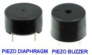
A piezo diaphragm will produce a click
when connected to 9v DC.
A piezo buzzer will produce a tone when
connected to a DC voltage.
A Piezo Buzzer contains a transistor, coil, and piezo diaphragm and produces sound when a voltage is applied. The buzzer in the circuit above is a PIEZO BUZZER.
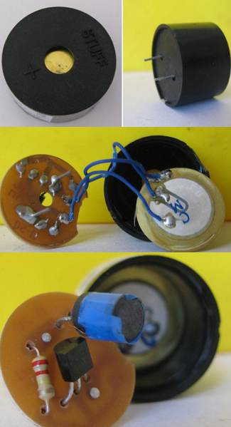
The circuit starts by the base receiving a small current from the 220k resistor.
The piezo diaphragm has a feedback sector that is capacitively coupled to the rest of the diaphragm.
The plate of the piezo induces a small voltage in the feedback sector that turns the transistor ON more.
This continues until the transistor is fully turned ON. At this point the voltage on the plate of the diaphragm is not increasing and the feedback sector receives no signal. This makes the transistor turn OFF and it almost disappears from the circuit. The collapsing magnetic field produces a voltage in the opposite direction and this puts a reverse voltage on the feedback sector to completely turn the transistor OFF. This allows the collapsing magnetic field to produce a higher voltage and the diaphragm is dished an enormous amount. This voltage has to "die down" to zero and then the slight current from the 220k will start to turn the transistor ON again to repeat the cycle. This timing creates the high-pitched sound.
TESTING A SPEAKER
A speaker (also called a loud
speaker) has coil of wire wrapped around a magnet but it does
not touch the magnet as it is wound on a thin cardboard former so
the coil will be pulled closer to the flux produced by the magnet when a current flows in the
coil.
When the current flows in the other direction, the coil moves away from
the magnetic flux.
This coil is called a voice coil and it is connected to a sheet of
thin card called a CONE and as the cone vibrates, the speaker reproduces
music or noise.
Use a multimeter on a low ohms scale to read the value of resistance of
the coil.
It can be as low as 2 ohms or as high as 100 ohms.
Replacing a speaker is easy. Just get one the same size and impedance and the job is done.
But there is a lot more to understand this simple replacement.
The principle of operation of a speaker is called ELECTROMAGNETISM and the strength of the "Pull" depends on the strength of the PERMANENT MAGNET and the magnetism produced by the coil.
The strength of the coil can be produced in two different ways.
The coil can consist of a few turns and a high current flows. Or it can consist of many turns with a very low current.
When you multiply the number of turns and the current you get a result called AMP-TURNS.
It is the AMP-TURNS that produces the FLUX (called MAGNETIC FLUX) and this flux interacts with the MAGNETIC LINES OF FORCE produced by the PERMANENT MAGNET to produce REPULSION or ATTRACTION.
Here's the amazing part: You can replace an 8-ohm speaker with 16 ohm, 32 ohm or 50 ohm and get the same (or even higher) output. That's because the number of turns on an 8-ohm coil multiplied by the current flowing through the coil may be equal to the number of turns on a 50 ohm coil multiplied by the current flowing through the coil. If the answers are identical, both speakers will produce the same output.
So, don't bypass the possibility of replacing a speaker with one having a higher impedance voice coil (VC). If the new speaker has a super-magnet, the output will be very impressive. A higher impedance will also put less stress on the output of the circuit and it will sometimes allow a higher voltage to be delivered to the speaker and thus allow proportionately higher current to flow.
A speaker with a weak magnet will produce a low output. Throw it out.
CONTINUITY TESTER
Now is an ideal time to introduce a simple piece of test equipment that will test all sorts of devices and circuits.
It is a CONTINUITY TESTER
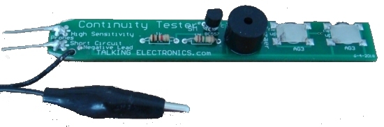
This piece of test equipment is available from Talking Electronics for
$2.50 plus postage.
It is very handy handy and very clever because it has 2 levels of
continuity.
The "short-circuit" probe detects low resistance and beeper-buzzer
produces a noise when a low resistance is present (up to about 50 ohms).
The High Sensitivity probe is amplified by the transistor and will
detect up to about 30k.
It's ideal for measuring and comparing a fault project with a project
that works as you can hear the different tones from the buzzer and
detect quite small differences in resistance.
You don't realise the importance of a simple piece of test gear like
this, until you get one. We use it all the time.
Now, back to the speaker discussion:
Most speakers have an 8R voice coil and the actual resistance may be
slightly lower than this.
Some speakers have a resistance of 16R, 32R or 50R and even 75 ohms.
You would think putting a 16R speaker in place of 8R would reduce the
sound output, but this is not always the case.
You can even use 50R or 75R and get the same performance.
This may sound amazing, but here is the reason.
The cone is deflected a certain amount due to the current flowing and
the number of turns.
These two values are multiplied together to produce a value called
AMP-TURNS.
If we have an 8R speaker with 80 turns and 100mA, the result is 0.1 x 80
= 8.
If we use a 16R speaker, the average current flow will be 50mA and the
number of turns will be about 160. The multiplication of
0.05 x 160 = 8.
The author then tried a 50R speaker and the sound output was equal to 8R
and the same with 75R speaker.
This might not apply in all situations, but the 75R speaker was slightly
larger and the ticking sound form the Metal Detector kit was
louder than using an 8R mini speaker.
To see if the cone of a speaker is undamaged, push it slightly and it
will move towards the magnet. If it does not move, it is bent or
damaged. If the cone is scratchy when pushed, it is rubbing against the
magnet.
A cone should be able to be pushed and pulled from its rest-state. If
not, it will produce a distorted sound.
TESTING A CIRCUIT
Whenever you test a circuit, the TEST EQUIPMENT puts "a load"
or "a change" on it.
It does not matter if the test equipment is a multimeter, Logic Probe,
CRO, Tone Injector or simply a LED and resistor.
There are two things you need to know.
1. The IMPEDANCE of the circuit at the location you are testing, and
2. The amount of load you are adding to the circuit via the test
equipment.
There is also one other hidden factor. The test equipment may be
injecting "hum" due to its leads or the effect of your body at absorbing
hum from the surroundings or the test equipment may be connected to the
mains.
These will affect the reading on the test equipment and also any output
of the circuit.
Sometimes the test equipment will prevent the circuit from working and
sometimes it will just change the operating conditions slightly. You
have to be aware of this.
The last section of this eBook covers High and Low
Impedance and understanding impedance is something you need to know.
The point to note here is the fact that the equipment (and the reading) can be upset by
hum and resistance/capacitance effects of test equipment. This is
particularly critical in high impedance and high frequency circuits.
TESTING INTEGRATED CIRCUITS (IC's)
Integrated Circuits
can be tested with a LOGIC PROBE. A Logic Probe will tell you
if a line is HIGH, LOW or PULSING.
Most logic circuits operate on 5v and a Logic Probe is connected to the
5v supply so the readings are accurate for the voltages being tested.
A Logic Probe can also be connected to a 12v CMOS circuit.
You can make your own Logic Probe and learn how to use it from the
following link:
http://www.talkingelectronics.com/projects/LogicProbeMkIIB/LogicProbeMk-IIB.html
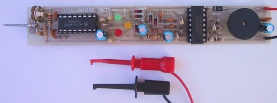
LOGIC PROBE with
PULSE
This is a very
simple transistor circuit to provide HIGH-LOW-PULSE indication for
digital circuits. It
can be built for less than $5.00 on a piece of matrix board or on a
small strip of copper clad board if you are using surface mount
components. The probe will detect a HIGH at 3v and thus the project can
be used for 3v, 5v and CMOS circuits.
Here is a simple Logic Probe using a single chip. The circuits have been designed for the CD4001 CMOS quad NOR gate and CD4011 CMOS NAND gate. The output has an active buzzer that produces a beep when the pulse LED illuminates (the buzzer is not a piezo-diaphragm but an active buzzer containing components).
SUPER PROBE MkII has 20 different features including a Logic Probe, capacitance tester, Inductance tester, and more.
To test an IC,
you need a circuit diagram with waveforms. These diagrams will show the
signals and are very handy if a CRO (cathode ray Oscilloscope ) is used to diagnose the
problem. The CRO will reproduce the waveform and prove the circuit is
functioning correctly.
A Logic Probe will just show activity and if an output is not producing
a "pulse" or "activity," you should check the power to the IC and
test the input line.
It is beyond the scope of this eBook to explain how to diagnose waveforms, however
it is important to know if signals are entering and exiting an IC and a
Logic Probe is designed for this.
SIGNAL INJECTOR
This circuit is rich in harmonics and is ideal for
testing amplifier circuits. To find a fault in an amplifier, connect the
earth clip to the 0v rail and move through each stage, starting at the
speaker. An increase in volume should be heard at each preceding stage.
This Injector will also go through the IF stages of radios and FM sound
sections in TV's.
TESTING AUDIO AMPLIFIERS and AUDIO IC's
The Super Probe MII described above has a "noise" function and a tone
function that allows you to inject a signal into an audio stage,
amplifier (made from discrete components) or an audio chip, and detect the output on a speaker.
Audio stages are very difficult to work-with if you don't have a TONE
GENERATOR or SIGNAL INJECTOR.
The signals are very small and not detected by a multimeter.
You can start anywhere in an amplifier and when a tone is heard, you
can keep probing until the signal is not present or louder. From this
you can work out which way the signal is travelling.
A Signal Injector is very handy for finding shorts and broken wires in switches, plugs, sockets
and especially leads to headphones.
You can determine the gain of a stage (amplification) by probing before
and after a chip or transistor and listen for the
relative increase in volume from the speaker.
You can also use your finger to produce "hum" or "buzz" if a
Signal
Injector is not available.
Nearly all audio problems are plugs, sockets and cracks in the PC board,
but finding them takes a lot of time and skill.
TESTING IC's - also called "CHIPS"
An Integrated Circuit is also called a "chip." It might have 8 pins or
as many as 40.
Some chips are ANALOGUE. This means the input signal is rising and
falling slowly and the output produces a larger version of the input.
Other chips are classified as DIGITAL and the input starts at 0v and rises
to rail voltage very quickly. The output does exactly the same - it
rises and falls very quickly.
You might think the chip performs no function, because the input and
output voltage has the same value, but you will find the chip may have
more than one output and the others only go high after a number of
clock-pulses on the input, or the chip may be outputting when a combination of inputs is recognised or
the output may go HIGH after a number of clock pulses.
ANALOGUE CHIPS
(also see above)
Analogue chips are AUDIO chips or AMPLIFIER chips.
To test these chips you will need three pieces of test equipment:
1. A multimeter - this can be digital or analogue.
2. A
Signal Injector
3. A Mini Bench Amplifier.
The Mini Bench Amplifier is available as a kit.
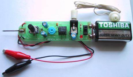
Start by locating the power pin with a multimeter.
If the chip is receiving a voltage, you can use the Mini Bench Amplifier
to detect an output.
Connect the Ground Lead of the Mini Bench Amplifier to 0v and touch the Probe tip on each of the
pins.
You will hear faint audio on the Input pin and very loud audio on the
Output pin.
If no input is detected, you can use a
Signal Injector to produce a tone.
Connect the clip of the Signal Injector to 0v and the probe to the
input pin of the amplifier chip. At the same time, connect the Mini
Bench Amplifier to the output pin and you will hear a very loud tone.
These pieces of test equipment can also be used to diagnose an amplifier
circuit constructed with individual components.
Amplifier circuits using discrete components are very hard to trouble-shoot and these pieces of
test equipment make it very easy.
It is always best to have data on the chip you are testing, but if this is not available, you will need three pieces of equipment:
1. A multimeter - this can be digital or analogue.
2. A Logic Probe,
3. A logic Pulser.
Firstly test the chip to see if power is being delivered. This might be anything from 3v3 to 15v.
Place the negative lead of the multimeter on the earth rail of the project - this might be the chassis, or the track around the edge of the board or some point that is obviously 0v.
Try all the pins of the chip and if you get a reading, the chip will have "supply."
Identify pin 1 of the chip by looking for the "cut-out" at the end of the chip and you may find a small dimple below the cut-out (or notch). This is pin 1 and the "power pin" can be directly above or any of the other pins.
Next you need to now if a signal is entering the chip.
For this you will need a LOGIC PROBE.
A Logic Probe is connected to the same voltage as the chip, so it will detect a HIGH and illuminate a red LED.
Connect the Logic Probe and touch the tip of the probe on each pin.
You will not know if a signal is an input or output, however if you get two or more active pins, you can assume one is input and the other is output. If none of the pins are active, you can assume the signal is not reaching this IC.
If only one pin is active, you can assume the chip is called a CLOCK (or Clock Generator). This type of chip produces pulses. If more than two pins are active, you can assume the chip is performing its function and unless you can monitor all the pins at the same time, you don't know what is happening.
This is about all you can do without any data on the chip.
If you have data on the chip, you can identify the input(s) and output(s).
A Logic Probe on each of these pins will identify activity.
A Logic Probe has 3 LEDs. Red LED indicates a HIGH, Green indicates a LOW and Orange indicates a PULSE (activity).
Some Logic Probes include a piezo and you can hear what is happening, so you don't take your eyes off the probe-tip.
It is important not to let the probe tip slip between the pins and create a short-circuit.
LOGIC PULSER
If you have a board or a single chip and want to create activity (clock pulses), you can use a Logic Pulser. This piece of test equipment will produce a stream of pulses that can be injected into the clock-line (clock input) of a chip.
You can then use a Logic Probe at the same time on the outputs to observe the operation of the chip.
You can also use the Mini Bench Amplifier to detect "noise" or activity on the inputs and outputs of digital chips.
This only applies if the frequency is in the audio range such as scanning a keyboard or switches or a display.
This is how to approach servicing/testing in a general way. There are thousands of digital chips and if you want to test a specific chip for its exact performance, you will need to set-up a "test-bed."
REMOTE CONTROLS
There are two types of remote control - Infrared and RF. Infrared is
used for short-range, line-of-sight for TV's DVD's etc.
A few faults can be fixed, but anything complex needs a new remote control.
Check the batteries and battery-contacts. See if the IR LED is illuminating by
focusing it into a digital camera and looking on the screen for
illumination.
The only other things are a sticky button, a worn-out button or a crack
in the PC board. Water damage is generally too much work to repair.
RF remote controls for cars, garage doors etc
need a second working unit to check the power output.
Here is a simple circuit that can be connected to an analog multimeter
to detect the signal strength at a very close range:
To hear the tone from a transmitter, the Mini Bug Detector circuit can be used:
.gif)
Any further investigation requires a circuit diagram so you can work out
what is actually being sent from the transmitter.
Most of the time it is a faulty switch, battery or contacts. Make sure
the setting is correct on the "dip switches" and use a working unit to
compare all your testing.
TESTING
There are basically two different types of circuit.
1. ANALOGUE CIRCUIT
An analogue circuit can also be called an AUDIO CIRCUIT and the voltages at different points in a circuit can be measured with a multimeter but the changes (the waveforms) will be quite small or changing at a rapid rate and cannot be detected by a multimeter.
You need a CRO to "see" the signals or a Signal Injector to inject a waveform into the circuit and hear the result on the circuit's speaker.
2. DIGITAL CIRCUIT
A digital circuit can also be called a "Computer Circuit" or "Logic Circuit" and some of the voltages can be measured with a multimeter (such as supply voltages) but the "signal lines" will be be changing from HIGH to LOW to HIGH very quickly and these signals are detected with a Logic Probe.
Here are some circuits with details of how to test the voltages.
Most circuits do not show voltages at various different points and we will explain what to expect on each "stage." is is the way to test all modules. You may know what they do but you may know nothing. The point is to be careful. Don't allow any of your probing to create a short-circuit as the energy in large capacitors (electrolytics) will destroy almost anything.
You can see the module has 3 inputs. They all convert the input voltage to 25v (or deliver 25v) to the top diode and this diode turns on a Darlington transistor that gradually rises "higher and higher" (as the 4 electrolytics charge). The transistor is turned ON via the 3 x 1k resistors and the base voltage is monitored by three zeners and a LED. When this voltage gets to 9.1v + 9.1v + 5.1v + 3.3v (for the LED), it cannot rise any further and the emitter reaches 0.6v less than this.
The first thing to do is connect a low voltage to the DC input and see of a voltage appears on the electrolytics.
If not, you measure the voltage on the ends of the 1k resistors and the 3 leads of the transistor. No voltage will mean the wiring or the top diode is not conducting or around the wrong way.
When you have voltage, increase the input voltage to more than 27v and the LED will illuminate. If not the zeners and or LED are faulty. If the LED comes on below 25v, a zener will be faulty.
The 3 voltages on the transistor should be almost the same after a short period of charging. If not, the transistor will be damaged.
Do no short-circuit the output terminals. The high current from the electrolytics will BLOW UP the output power diode.
Touch a 8R 5watt power resistor on the top of the output screw terminals and look for the spark. Or you can use a fairly large 12v motor. If it does not work, the diode is damaged.
The transistor does not pass a high current at any time and is not heat-sinked. When the output is delivery energy to a load, the output voltage drops to a few volts and the red wire on the circuit diagram reduces the voltage on the base to a low value and prevents the circuit charging the capacitors.
This module is used to show how to perform "testing".
A "STAGE"
A stage is a set of components with an input and output. A "stage" can
also be called a "Building Block."
Sometimes it has a capacitor on the input and one on the output.
This means the stage is completely isolated as far as DC is concerned.
The stage has a supply (a DC supply) and it is producing its own
voltages on various points on the "stage." It can only process (amplify)
"AC." (signals).
Sometimes the stage can be given a name, such as small-signal amplifier,
push-pull amplifier or output.
If the stage has a link or resistor connected to a previous stage, the
previous stage will have a "DC effect" on the stage. In other words it
will be biasing or controlling the voltages on the stage. The stage may
be called a "timer" or "delay" or "DC amplifier."
It is important to break every circuit into sections. This makes testing
easy. If you have a capacitor at the input and output, you know all the
problems lie within the two capacitors.
In a digital circuit (no capacitors) you need to work on each IC
(integrated Circuit) and test the input for activity and all the
outputs.
Once you have determined if the circuit is Analogue or Digital, or a
combination of both, you have to look at the rail voltage and work out
the size or amplitude of the voltage or waveform.
This is done before making a test, so your predictions are confirmed.
You will need a multimeter (either Digital or Analogue) a
Logic Probe and a Signal Injector (Tone Generator).
An analogue meter has the advantage that it will detect slight
fluctuations of voltage at a test-point and its readings are faster than
a digital meter. A digital meter will produce an accurate
voltage-reading - so you should have both available.
HIGH IMPEDANCE AND LOW IMPEDANCE
Every point in a circuit has a characteristic called "IMPEDANCE." This
has never been discussed before in any text book. That's why it
will be new to you.
In other words, every point will be "sensitive to outside noise."
An audio amplifier is a good example. If you put your finger on the
active input, it will produce hum or buzz in the speaker. This is
because it is a HIGH IMPEDANCE line or high impedance section of the
circuit.
The same applies to every part in a circuit and when you place Test
Equipment on a line for testing purposes, the equipment will "upset" the
line. It may be very slight but it can also alter the voltage on the
point CONSIDERABLY.
We have already mentioned (above) how a cheap multimeter can produce a
false reading when measuring across a 1M resistor.
That's why you need high impedance test Equipment so you do not
"load" the point you are testing and create an inaccurate reading.
The word Impedance really means resistance, but when you have
surrounding components such as diodes, capacitors, transistors, coils,
Integrated Circuits, supply-voltages and resistors, the combined effect is very
difficult to work out as a "resistance" and that's why we call it
"Impedance."
The term "High and Low Impedance" is a relative term and does not
have any absolute values but we can mention a few points to help you
decide.
In general, the base of a transistor, FET input of an IC are classified
as HIGH IMPEDANCE.
The output of these devices are LOW IMPEDANCE.
Power rails are LOW IMPEDANCE.
An oscillator circuit and timing circuit are HIGH IMPEDANCE.
A LOAD is low impedance.
And it gets tricky: An input can be designed to accept a low-impedance
device (called a transducer or pick-up) and when the device is
connected, the circuit becomes LOW impedance, but the input circuitry is
actually high impedance.
The impedance of a diode or LED is HIGH before the device sees a voltage
higher than the junction voltage and then it becomes LOW Impedance.
Impedance is one of the most complex topics however it
all comes down to testing a circuit without loading it.
That's why test equipment should have an input impedance
higher than 1M.
The first circuit we will investigate is the Mini Bug Detector,
shown above and below. Points on the circuit have been labelled A, B, C etc:
.gif)
Point A - The first transistor is "self-biased" and will have 0.6v
on the base. The antenna is connected to a 20 turn coil and you might
think the coil will "short" the signals to earth.
But the coil and 470p capacitor form a circuit that oscillates at a high
frequency when the antenna wire picks up stray signals. The coil and
capacitor actually amplify the signals (see Talking Electronics website:
Spy Circuits to see how a TANK CIRCUIT works) and these signals
enter the base of the first transistor.
This is classified as a HIGH Impedance section because the signals are
small and delicate and any loading via test equipment will kill them.
The first transistor amplifies the signals about 70 times and they
appear at Point B.
The signal passes though a 22n to Point
C and the transistor amplifies the signal about 70 times to point
D. Point C is classified as high impedance as any voltage
measurement at this point will upset the biasing of the stage as a few
millivolts change in base-voltage will alter the voltage on the
collector considerably. Point D is classified as low impedance as
any voltage-testing will not alter the voltage appreciably.
The output of the second stage passes through a capacitor to the join of
two diodes. These two diodes are not turned on because the voltage at
Point E can never rise above 0.7v as this is the voltage produced by
the base-emitter of the third transistor.
The purpose of the two diodes is to remove background noise. Background
noise is low amplitude waveforms and even though the transistor is
turned on via the 220k, low amplitude signals will not be received. The
third transistor works like this: It cannot be turned ON any more
because any waveform from the 22n will be "clipped" by the bottom diode
and it will never rise above 0.6v.
So, the only signal to affect the transistor is a negative signal - to
turn it OFF.
Firstly we have to understand the voltage on the 22n. When the second
transistor is sitting at mid-rail voltage, the 22n gets charged via the
2k2 and lower diode. When the transistor gets tuned ON, the collector
voltage falls and the left side of the 22n drops. The right side of the
22n also drops and when it drops 0.6v, the top diode starts to conduct
and when the voltage on the 22n drops more than 0.6v the third
transistor starts to turn OFF. This effect is amplified by the
transistor at least 100 times and appears at Point F. All the
voltages around the two diodes are classified as HIGH Impedance as any
piece of test equipment will upset the voltage and change the output.
There are some losses in amplitude of the signal as it passes through
the 22n coupling capacitors but the end result is a very high strength
signal at point G. The 4th transistor drives a 10mH
choke and the mini piezo is effectively a 20n capacitor that detects the
"ringing" of the inductor to produce a very loud output.
The 22n capacitor on the collector eliminates some of the background
noise. The choke and piezo form an oscillatory circuit that can
produce voltages above 15v, even though the supply is 3v.
The 47n capacitor at Point J is to keep the supply rails "tight" (to
create a LOW Impedance) to allow weak cells to operate the circuit.
The "Power-ON" LED tells you to turn the device off when not being used
and Point L is the power supply - a low impedance line due to the
47u electrolytic.
Testing the Mini Bug Detector
To test the Mini Bug Detector, you will need a Signal
Injector.
Place the Injector on Point G and you will hear a tone. Then go
to E, C and A. The tone will increase in volume. If
it does not increase, you have pin-pointed the faulty stage.
The next circuit is a combination of digital and analogue signals.
It is a Logic Probe:
.gif)
The voltage on a circuit (to be tested) is detected by the probe at
Point A of the circuit above and the "tip" is classified as
"reasonably high impedance" as it has a 220k resistor between the tip
and 0v rail. The 1M reduces the impedance by about 20% but the inputs of
the two inverters have no effect on the "tip" impedance as they are
extremely high input-impedance devices.
The 1M trim pot is designed to put put a voltage on point B that
is slightly higher than mid-rail so the green LED is turned off.
Point A will see a voltage below mid-rail and point C will
be HIGH. Point C and F are low-impedance outputs.
When the tip of the probe is connected to a LOW voltage, Point B sees a
LOW and Point F goes LOW to illuminate the green LED. At the same time
it removes the "jamming voltage" produced by the diode between pin 4 of
the 4049 and pin 3 of the 74C14 and the oscillator between points H
and J produces a low-tone via the 100k resistor and 22n to indicate
a LOW.
When the probe tip sees a HIGH, a lot more things happen.
Point C goes LOW and turns on the red LED. At the same time
the 100p is in an uncharged state and the right lead goes LOW. This
takes the left lead LOW as the left lead connects to a HIGH Impedance
line and pin 9 goes LOW. This makes point E HIGH
and since the 1u is in an uncharged state, pin 11 goes HIGH. This makes
point G LOW and the diode between pins 9 and 12 keeps pin 9 LOW
and takes over from the pulse from the 100p. The yellow LED is
illuminated. The 1u starts to charge via the 470k and when it is approx
half-charged, pin 11 sees a HIGH and point G goes low. This
creates the length of pulse for the yellow LED.
At the same time, Point L goes LOW because the "jamming diode"
from pin 2 of the 4049 goes low and allows the inverter between point L
and N to produce a tone for the piezo.
In addition, Point I goes HIGH and quickly charges a 1u
electrolytic. This removes the effect of the jamming diode on pin 5 of
the 74C14 and a low frequency oscillator made up of 68k and 1u between
pins 5&6 turns on and off an oscillator between points O and R
to get a beep. The mini piezo is driven n bridge mode via the two gates
between points QT and PS.
Point U is a 1u electrolytic to reduce the impedance of the power
rail and Point V is a protection diode to prevent damage if the
probe is connected to the supply around the wrong way.
Testing the Logic Probe
You can test the Logic Probe with the simple Logic
Probe with Pulse project described above. It will let you know if
each point in the circuit is HIGH or LOW. You will also find out the
difficulty in testing the points that are HIGH Impedance, as the Probe
will upset the voltage levels and the reading may be inaccurate.
More circuits will be added here in the future.
You need to read lots of other sections in this eBook, including the section on measuring across a resistor with a multimeter, and high impedance circuits, to fully understand the complexities of a VOLTAGE DIVIDER CIRCUIT.
It is one of the most important BUILDING BLOCKS to understand. Even though it may consists of two components, you have to understand what is happening between these two components. You have to realise there is a voltage at their join that will be rising and falling due to one of the components changing RESISTANCE.
Sometimes you can work out the voltage at the join by using Ohm's LAW but quite often it will be impossible as it is changing (rising and falling) during the operation of the circuit.
At the beginning of this discussion we will only dealing with DC circuits and the voltage across a particular component will be due to its RESISTANCE. We are not going into any formulas, as it is very easy to measure the voltages with a multimeter set to VOLTS and you will have an accurate result.
The simplest two components in series are resistors. They always have the same resistance during the operation of a circuit and the voltage across each will not change.
In a further discussion we will cover "resistors" that change value according to the temperature. These are called THERMISTORS. And we have "resistors" that change value according to the light they receive. These are called LIGHT DEPENDENT RESISTORS (LDR's) or PHOTO RESISTORS.
A transistor that is partly or fully turned ON can be considered to be similar to a resistor.
In these 3 cases we need to measure the voltage at the join with a voltmeter as it will be a lot of work to measure the resistance and work out a value.
You can also keep a voltmeter on the joint and watch the voltage change.
Finally we have some components that produce a fixed voltage across them (or nearly fixed) and the remaining voltage is dropped across a resistor. These components MUST have a resistor connected in series to limit the current and allow the component to pass the specified in the datasheet.
These devices include LEDs, diodes and zener diodes. A LED will have a fairly fixed voltage across it from 1.7v to 3.6v depending on the colour. A diode will have a voltage of 0.7v across it when it is connected to a voltage via a resistor. And a zener diode will have a fixed voltage across it when it is connected with the cathode to the positive rail via a resistor. The voltage across it will be as marked on the zener.
The concept of a VOLTAGE DIVIDER is very simple, but it takes a lot of understanding because both VOLTAGE and CURRENT are involved in the UNDERSTANDING-PROCESS.
Each component has a resistance and this can be measured with a multimeter. When two components are connected in series, a current will flow and a voltage will develop across each item.
More voltage will develop across the item with the higher resistance and the addition of each voltage will always equal the supply voltage.
That's the simple answer.
There is a little more involved . . . It is the word CURRENT. Here is an explanation:
Suppose we have a 1k and 2k resistor on a 12v supply. The voltage at the join will be 4v.
In other words, there will be 4v across the 1k and 8v across the 2k.
If we have a 10k and 20k resistors in series, the voltage will also be 4v at the join.
If we have a 100k and 200k resistors, the voltage will also be 4v at the join.
The voltage will be the same in all cases, but the current will be different. The current in the second case will be one-tenth and only one hundredth in the third case.
If you want to go further, place a one ohm and two ohm in series and get 4v. But the resistors will get very hot and burn out very quickly.
Why do we have to chose between using 1k, 10k and 100k set-ups? Because different amounts of current will flow in each set-up. This current is called BLEED CURRENT and is basically "WASTED CURRENT." But it may be only way to design a circuit.
How do you choose? Basically you measure the current flowing through the voltage divider and one-fifth of this current will be the current you can "tap-off" to the circuit you are supplying the 4v to. You can turn the circuit around the other way and deliver 8v. In the above example with 1k and 2k, the "bleed current" will be 4mA and you can only supply 1mA to your project.
WHY?
Because the current you take from the voltage divider will make the 4v reduce to a lower voltage (3.5v) and if you take more than 1mA, the voltage will fall to less than 3v.
A voltage divider is like supplying a circuit with a very old and weak battery.
THE VOLTAGE DOUBLER
Many circuits use a capacitor to increase the voltage.
Firstly you have to look at a circuit and then realise "it is designed to increase the
voltage" and then look at the features of this type of circuit.
If the incoming voltage is 12vAC, the peak will be 17v and the output
can be as high as 32v. And it will be DC.
The electrolytic used in this type of circuit may get hot or warm,
depending on the current and it will gradually dry out. This will reduce
the output voltage -the voltage will sag when a load is applied.
This is the first component to replace.
The simplest voltage doubler is called a CAPACITOR INPUT VOLTAGE
DOUBLER:
If the output voltage is very high, you can use 2 electrolytics:
The same circuit can be used to produce a positive and negative output:
If the input voltage to the doubler section is DC, as shown in the following 555 VOLTAGE DOUBLER circuit, you will have to "jack-up" the voltage on the electrolytic by taking the negative lead of the electrolytic to the negative rail to charge it and then take the negative lead to the positive rail to deliver the voltage to the output section:
The amount of current that can be delivered by this type of circuit
depends on the value of the electrolytic and the frequency at which the
circuit operates.
SOLDERING
Here are three 30-minute videos on
soldering.
1.
TOOLS
2.
Soldering components
3. Soldering
SURFACE MOUNT
components
Soldering skills is one of the most important skills for an electronics
person.
I have many projects brought in for repair and the only fault has been a
poorly soldered
connection.
You must use a temperature controlled soldering iron and it is a simple
matter to adjust the temperature correctly.
Turn the temperature down and let the iron heat up. Gradually increase
the temperature until the solder JUST MELTS.
This is your starting point. Increase the temperature slightly and if
the joint is taking too long to melt the solder, increase the
temperature slightly.
There are two points of view on this subject.
One school of thought says to keep the temperature low to prevent
damaging the components and the other says to increase the temperature
considerably and perform the operation VERY QUICKLY.
I have followed both methods and have not damaged a component in 40
years.
So, it all boils down to quick and efficient soldering and taking the
least time to complete each joint.
But here's something that has never been covered before.
Some Chinese solder is marketed as 60/40 solder with rosin core. When
this was tried at the normal temperature of soldering, the solder did
not melt quickly and formed lumps and you could watch it harden with a
very dull finish.
The soldering iron had to be turned up to full heat to get it to melt
quickly.
THIS IS NOT THE SORT OF SOLDER TO USE.
This sort of solder WILL damage a component because the temperature is
HIGH and the time is LONG.
For the same cost you can buy Chinese Eutectic solder 63/37 and it melts
at a very definite point that is equal to the quality solder available
in Australia.
Soldering relies on CONDUCTION -heat conduction, cleanliness and speed.
Repairing items needs skill in removing components, testing them and
replacing them or using a new component.
In the process you don't want to damage a good component or the PC
board.
So you have to be careful.
You can pull a component off a board with your fingers or a pointed-nose
pair of pliers if you are quick and heat all the leads at the same time.
To do this, you need to add solder to each joint so the iron will get
heat conduction to all the joints at the same time.
You must use resin (rosin) cored solder so the solder and iron is clean
and ready to do the desoldering.
Another way to prepare the component for removal is to buy a bottle of
solder flux and dab it onto each joint and then use a clean piece of
de-solder wick to remove all the solder.
When you touch the desolder wick with the iron, the flux will splutter
and heat up and then you will see the solder flowing onto and into the
wick. Do this to all the joints and then move the wire with pliers so it
is disconnected from the hole.
You can remove solder from a hole by adding more solder than dab the
solder flux on the hole and use a new piece of desolder wick.
You can also remove solder from a hole by feeding tinned copper wire
into the hole with a hot soldering iron and letting the tinned copper
wire absorb the solder.
Or you can feed enamelled wire into the hole and make sure the enamel is
not removed from the wire so the enamelled wire will push and pull into
the hole and remove the solder while heating the hole with a soldering
iron.
The third method is to use a needle that does not accept solder and push
and pull it through the hole while heating the hole with a soldering
iron.
Finally, you can heat up the solder in a hole and tap the board on the
bench very hard and the hole will be clean.
If you want to remove a chip, you can place the board over a gas stove
and heat up the underside of the board and remove the chip with long
nose pliers . . . VERY QUICKLY.
Some solder flux is highly conductive, so remove it with acetone before
fitting a new component or you will think the new component is "leaky."
TESTING A MOTOR
Strictly speaking, a motor is not an electronic component, but since a
website gave a useless description on testing motors, I have decided to
supply the correct information.
The only REAL way to test a motor is to have two identical motors and
check the torque by connecting them to a low voltage and trying to stop
the shaft with your fingers. This will give you two results.
Firstly it will let you know the torque of the motor.
This is the twisting effect of the shaft. There is no way to determine
the torque by knowing the voltage or current.
The unknown factor is the strength of the field magnets (permanent
magnets) and this
determines the torque.
Secondly, feeling the shaft will let you know if the torque is even for
a complete revolution.
By having two identical motors, you can see if one has a lower torque.
Almost nothing can go wrong with a motor except for the
brushes. If the brushes wear out, additional resistance will be produced
at the interface between the brush and commutator and this can be
detected by allowing the shaft to rotate slowly and feeling the
resistance as it revolves. A 3-pole motor will have six places where
the strength is greatest. A 5-pole
motor will have 10 places of strength, when the motor is not powered.
When the motor is powered, this changes to 3 places and 5 places.
If the strength is weak or not uniform, the motor is faulty.
You cannot test a motor with a multimeter as the resistance of the
armature winding is very low and if you spin the motor with your fingers, the
back voltage produced by the spinning, increases the reading on the
meter and is false.
The best way to test a motor is to supply a low voltage and put an
ammeter in series with the positive lead. You will see the current
change as the shaft is held slightly with your fingers.
Micro motors have a coreless armature. This means the 3 windings for the
armature are wound on a machine then bent slightly into shape and glued.
A circular magnet with 3 poles is in the centre and the armature rotates
around this.
This type of motor is reasonably efficient because the armature is the
greatest distance from the point of rotation, and the motor reaches full
RPM very quickly because the armature has very little inertia.
I have not heard of the armature-winding flying apart but if you hear
any scraping noise, it may be the winding.
3-pole, 5-pole and micro motors can be found in printers, eject
mechanisms of CD players, toys, RC helicopters, cars etc and they rarely
fail.
Motors do not work on "voltage." They actually work on CURRENT and
as you increase the voltage, more current will flow and produce a
stronger magnetic field (by the winding on each pole). This magnetic
field will be attracted by the permanent magnet surrounding the armature
and repelled by the surrounding permanent magnet, depending on where the
face of the pole is, during each revolution.
If the permanent magnet is not very strong, the
interaction of the magnetic fields will be very weak and thus the torque
will be small, but the motor will increase to a higher RPM in an attempt
to generate sufficient back-voltage.
Because motors work on "current" you must have a high current available
when you increase the voltage as the motor will require short bursts of
high current during part of each revolution.
It is the combination of voltage and current (called watts) that gives
the motor "strength" (torque) as well as the "strength" of the permanent
magnets (called the field magnets) and the number of turns of wire on
each pole (and the gauge of wire).
Basically, if a motor is hard to spin, and has 3 "hard spots" on each
revolution, it will be powerful.
A 2-pole motor does not self-start and will spin in either direction.
But a 3-pole motor will self-start and you can control the direction
of rotation.
A 5-pole motor has a lower RPM. It is slightly smoother in output but
may
not be more powerful than a 3-pole version.
A 3-pole motor will have an RPM in the range of 10,000 to 30,000 RPM.
A 5 pole motor can be as low as 6,000 to 8,000 RPM. The RPM of a 5-pole
motor (and 3-pole) can be reduced by supplying a lower voltage. Some
5-pole motors will reduce to 600RPM when the voltage is reduced from 12v
to 6v. The torque from a 5-pole motor is the same as a 3-pole motor if
the armature diameter is the same and the strength of the permanent
magnets are the same and the air gap is the same and the magnetic field
produced by the armature is the same. A certain voltage and current
cannot produce greater torque, just because the motor has more poles.
Basically, the RPM of a motor when not loaded will increase until the
energy required to rotate the armature equals the energy being delivered
by the voltage and current. At the beginning, the energy input is very
high and the motor increases in RPM. As it increases in RPM, the energy
required to do this increases and at the same time the increase in back voltage
it produces causes the incoming energy to reduce. Eventually these two
become equal and the RPM is maintained. If a motor has very few
turns on each pole, it will need to achieve a higher RPM to produce the
back voltage needed to achieve equilibrium. If the magnets are weak, the
RPM is also higher.
A coreless motor has a very light armature and it does not require very
much energy to rotate it. That's why it achieves a very high RPM.
The RPM is also very high because the "back-voltage" - voltage produced
when the windings pass a magnet - is not very high. With the motor
having an armature, the armature not only concentrates the magnetic flux
produced by the winding but it also receives the magnetic flux from the
permanent magnets and this flux is in the opposite direction to that
produced by the winding and puts a reverse voltage on the input voltage
and thus the current decreases. With a coreless motor, the winding has
to revolve at a much higher RPM to active this reverse voltage as the
magnetic flux from the magnet has to actually pass though the copper
wire of the winding to produce the back-voltage and this is not nearly
as efficient as having a metal core.
A motor with "permanent magnets" is called a DC motor as it will not
work on AC. If the magnets are replaced with a coil, it will work on AC
and it will be called a "shunt wound" motor if the field coil is
connected across the same terminals as the brushes or a "series wound"
motor if the field coil is in series with the armature.
By reversing the two wires to the field winding, the motor will reverse.
If the armature is long, the motor will produce more torque because the
interaction between the magnetism of the pole and the associated field
of the permanent magnet is greater.
With a 3-pole motor, one pole is receiving full voltage and it will be
NORTH. The other two poles will be in series and producing less magnetic
flux and will be SOUTH. The combination of attraction of one pole and
repulsion of two poles produces a "pulling" and "pushing" effect, that
causes the armature to rotate in the clockwise direction.
You cannot predict, design or work out the RPM of a motor because it
depends on so many things.
Things like the strength of the permanent magnets, the distance between
the poles and the magnets (called the air gap), the effectiveness of the faces of the poles
and obvious things like the number of turns, the voltage and the number
of poles.
You simply build a motor and change the number of turns and do this 4 or
more times and generate a list of results. Then you can change the
alnico magnets (ferrite magnets) for super-magnets and the size of the
armature and then work out where you want to go.
Now we come to a secret that no-one has ever mentioned.
As you increase the voltage to a motor, the current will increase and the attraction and repulsion of the magnetic field between the pole and the permanent magnets will increase and the motor will have more torque and this will give it a higher RPM. But a point will be reached where the magnetic field produce by the winding on a pole will be greater than the magnetic field produce by the permanent magnet and suppose the magnet is N-pole and the winding produces a North pole. As the flux from the armature increases, the repulsion increases but when it is greater than the permanent magnet, the repulsion reaches a maximum and now the armature sees the permanent magnet as a piece of material that it can be attracted-to. Thus the torque of the motor has reached a maximum.
EMF
When a motor is revolving, you can see sparks between the brushes and the segments of the commutator. These sparks are due to the voltage produced by the coils on each pole. This voltage is called "back voltage" or "spike voltage" can be very high - up to 100 times higher than the supply voltage and this voltage can damage the driver transistor. This voltage has very little current but transistors are very susceptible to voltages and can be damaged instantly.
The name given to this voltage is called BACK EMF. It is generally considered to be a voltage that has very little current. In other words it cannot do any "work." But it can damage a transistor instantly. Sometimes a capacitor across the terminals of the motor will reduce the voltage and protect the driver transistor.
The Servo
The servo is a very low-cost item due to the enormous quantity produced and you have to expect some defective units are sold from the sellers on the web. For $3.00 you cannot expect every unit to be perfect and here are some of the defects and tests.
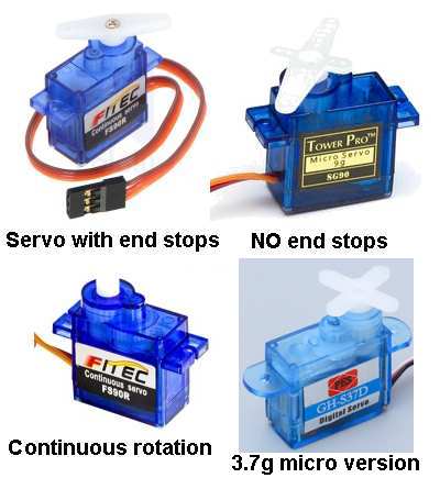
There are 4 different types of low-cost plastic-gear SERVOS. The first model
to be produced allowed the arm (called a HORN) to be rotated 270° and
the arm stopped at the point via a "stop" inside the servo. The
electronics inside the servo did not allow the arm to pass beyond this
point but sometimes the servo got jammed and would not come out of this
jammed position.
The next model to be produced had no stops and if you rotated the arm
past the point where the "stop" would normally be located, the
electronics would rotate the arm to a position in the range of 0° to
about 270°. This prevented the problem of "jamming." The model with no
end stops has the ID: SG90.
A more-expensive model has now been produced with a completely different
program in the microcontroller and the arm will rotate 360° and the
microcontroller will accept a program to rotate the arm in a continuous
rotation mode. The cost about $10.00 with shipping and you need to
have a project that sends the correct signals for continuous rotation.
Some of the servos fail to work and it could be the wiper on the
potentiometer not making good contact. If the arm jitters as it moves,
the wiper on the pot is most likely the problem.
Finally a micro version is also available for about $10.00 with stops.
All these servos can be taken apart and the microcontroller removed and
the motor connected to 2 wires so the servo becomes a motor and gearbox.
This is the cheapest and smallest motor and gearbox for all sorts of
applications and the internal stop needs to be removed to get continuous
rotation.
If you find the plastic gears are wearing out in your application, you
can buy the metal-gears version.
I have bought hundreds of servos and the ones that did not work were
converted to motor/gearbox versions.
All the servos work on 4.5v to 6v and have a 3.3v regulator inside. The
motor is most powerful on 6v and the supply should not be increased
above 6v or 8.5v (according to spec sheets).
CORELESS MOTOR
There are two types of miniature motors. One is called the 3-pole
motor and the other is called a coreless motor
This means it has no metal where the wire is wound to create a magnet
pole. The 3-pole motor has 3 legs or 3 arms or 3 poles and that’s why it
is called a 3-pole motor
The coreless motor has the wire wound on a mandrel land this is a
rectangular shape to create the rectangle winding. Another winding is
then wound near and interlaced with the first and then more windings are
wound to create a circular structure.
The windings are wound on an angle to create even torque. This is only
impotent when the motor has to start under load.
The skill is getting all the lose wires and windings glued together to
prevent them flying apart when the winding is spinning. It is only
through automation that these motors can be produced for less
than a dollar.
The windings are placed over a magnet and rotate around the magnet.
The flux from the permanent magnet is expanding outwards with a North
and South pole and each of the
windings create a coil where the magnetism flows through the centre and
co-insides the the permanent magnet flux. The
only time when there is a twisting reaction between these two fields is
when the winding is at the edge of the field coming from the permanent
magnet. There is no twisting when the two are aligned. The windings are
partially interlaced and skewed to create even rotation and 3 4 or more
windings will create self-starting.
The ends of the windings are terminated at a commutator, just like a
3-pole motor and when the stiff windings are placed around the permanent
magnet and voltage is applied, they will rotate.
These motors end up with advantages. There is no heavy metal parts
spinning around (this consumes a very large amount of the motors energy).
The actual magnetic interaction occurs at a greater distance from the
centre, compared to a 3-pole motor. This has the result of increase
torque. And although the magnetic field of
the air winding is not “guided” or "condensed" by a magnetic piece of metal, the other
two features make the coreless motor equal or better than the 3-pole
version.
These motors are not worth fixing. They are so cheap.
The only thing that goes wrong is the brushes. They wear out. Some
motors have carbon brushes and this is a tiny carbon block on the end of
the brushes that makes contact with the commutator.
TESTING COMPONENTS "IN-CIRCUIT"
You can test components while they are IN CIRCUIT, but the
surrounding components will have an effect on the results.
You can get all sorts of "In-Circuit" testers. They are expensive and
offer little more accuracy than a multimeter.
In-Circuit testing with a multimeter can give you the same results as a
tester.
All you have to do is turn the project ON and use a multimeter (set to
voltage) to determine the voltage at various points. It is best to have
a circuit of the equipment so you can what to expect at each point.
Only major departures from the expected can be located in this way.
Obviously the first thing to look for is burnt-out components. Then feel
components such as transistors for overheating.
The look for electrolytics that may be dry. Sometimes these have changed
colour or are slightly swollen.
If they are near hot components, they will be dry.
For the cost of a few dollars I change ALL THE ELECTROLYTICS in some
pieces of equipment, as a dry electrolytic is very difficult to detect.
Testing a transistor "in-circuit" is firstly done with the supply ON.
That's because it is quicker.
Measure the voltage between ground and collector.
In most cases you should get a voltage of about half-rail. If it is
zero, or close to rail voltage, you may have a problem.
Turn off the supply and use the multimeter on low-ohms to measure all
six resistances between the leads.
A low resistance in both directions on two leads will indicate a fault.
Resistors almost NEVER go "HIGH." For instance, a 22k will never go to
50k. However a low-value resistor will "burn-out" and you will read the
value of the surrounding components.
Don't forget, some low-value resistors are designed to burn-out (called
fusible resistors) and anytime you find a damaged low-value resistor,
you will need to look for the associated semiconductor.
You can replace the resistor quickly and turn the circuit ON to see it
burn out again.
Alternatively you can trace though the circuit and find the shorted
semiconductor.
It's always nice to "see the fault" then "fix the fault."
Sometimes a transistor will only break-down when a voltage is present,
or it may be influenced by other components.
When the piece of equipment is turned OFF, you can test for resistance
values. The main thing you are looking for is "dry joints" and
continuity. Dry joints occur around the termination of transformers and
any components that get hot. Rather than wasting time checking for dry
joints, it is better to simply go over the connections with a hot iron
and fresh solder.
You may need to check the continuity of a track (trace) and it may go
from one side of the PC board to the other.
Use a multimeter set to low-ohms and make sure the needle reads
"zero-ohms."
It is very dangerous to do any testing on a project using a multimeter
set to "amps" or "milliamps."
You cannot test "current flowing through a component" by placing the
probes across a component. You will simply over-load the rest of the
circuit and create a problem.
To find out if current is flowing though a circuit or a low-value
resistor, turn the project ON and measure the voltage either across the
component or the voltage on one end then the other.
A voltage-drop indicates current is flowing.
That's about it for testing "in-circuit." Use the rest of this eBook to
help you with diagnosis.
Don't think an IN-CIRCUIT COMPONENT TESTER is going to find a fault any
faster than a multimeter. They all use a multimeter principle.
This basically means the component takes more current than normal and it may fail completely or simply take more current and the operation of the circuit may be reduced only a small amount.
The resistance of the component may reduce a very small amount but this may have a very large effect on the operation of the circuit.
For instance, two turns in the horizontal or vertical winding of a yoke on the picture tube or monitor may arc and weld together and reduce the size of the picture on the screen, but measuring the winding will not detect the difference in resistance.
The same with the windings on a motor and a short between two winding in a transformer.
If the "short" is between two near-by turns, the change in resistance will be very small. If the "short" is between to different layers, the resistance will be reduced and it may be detected.
When a "short" occurs, the winding turns into a transformer. To be exact, an AUTO-TRANSFORMER.
In the following diagram you can see a normal winding in fig A:
Fig B shows two turns touching each other and if the wire is enamelled,
the coating has been damaged so the copper wire from the two turns is
touching. This is called a SHORTED TURN.
In fig C you can see two turns touching.
In fig D the shorted-turn has been moved to the other side of the symbol
to show the effect it has on the operation of the winding.
The shorted-turn is exactly like the secondary of a transformer with a
"jumper" across the output.
This will produce a very high current in the secondary.
A very
high current flows through the shorted turn and this changes the
operation of the rest of the winding.
1. In most cases a SHORT CIRCUIT can be detected by feeling the
additional heat generated by the component.
2. Next, turn off the supply and measure the resistance of the
component. If it is lower than expected, the component will be faulty.
3. Next, measure the voltage across the component. If it is lower than
normal, the component will be faulty.
4. Next, measure the current taken by the component. If it is higher
than normal, the component will be faulty.
5. If the component is an inductor, such as a motor, coil or
transformer, you can use an inductance meter. Compare a good winding
with a faulty winding. Sometimes the fault will disappear because an arc
develops across the fault when the component is operating.
INTERNAL AND EXTERNAL SHORTS
An internal short refers to
two windings shorting
together and the winding has a very high resistance between the winding
and the frame on which it is wound. An external short refers to a winding shorting to the frame of
the component - such as one of the armature windings shorting to the
metal core, around which the wire is wound.
This may not be important unless another winding shorts to the metal
frame and creates "inter winding" problems (inner winding
problems is within the same winding).
The opposite to a short circuit is an OPEN CIRCUIT.
This is generally a broken lead or contact or a wire that has
"burnt-out" or been "eaten-away" by acid attack or galvanic action by
water and voltage (current).
1. No current will flow when an OPEN CIRCUIT exists.
2. The voltage on each end of the OPEN CIRCUIT will not be the same.
3. Measure the current across the OPEN CIRCUIT and determine if excess
current is flowing.
4. Join the two ends of the OPEN CIRCUIT and see if the circuit operates
normally.
HEATSINKS
This is not an electronic component
but it can certainly affect the operation of a circuit.
If you cannot hold your fingers on a heatsink, it is getting too hot.
This is because the actual location where the heat is being generated is
much hotter than the part you are touching.
Transistors and IC's can withstand a high temperature but if they go
above this temp, they BLOW UP.
They also have a shorter life when operating at a high temperature.
The secret to a good heatsink is called an INFINITE HEATSINK.
This is the metal frame of a case.
There are lots of charts and data on choosing a heatsink but they don't
take into account two factors:
Sometimes a circuit takes a very high current for a short time and this
creates a high temperature gradient. This will cause the transistor to
get very hot and fail.
The solution is to have two or more transistors in parallel to separate
the "heat spots."
The second problem with designing a heatsink is the unknown location of
the heatsink and the air-flow. Products placed on a shelf or in a cupboard will
get very little air-flow.
Remember: some transistors are mounted on thermal insulators. This means
the transistor will have a voltage on it but the heatsink will be zero
voltage.
The temperature of the transistor will be MUCH HIGHER than the heatsink
under the transistor and the transfer of the heat from the transistor to
the heatsink will be very slow. This can be the cause of the transistor
failing. Sometimes the transistor will fail because insulation is high temp
plastic and it gets brittle. The plastic can carbonise and leak and
sometimes a voltage can flash through the insulator. Some amazing things
have happened under these transistors and you may need to pull it apart
and replace all the insulation.
Finally, feel the heatsink after 15 minutes and feel right up to the
transistor. If you cannot touch the transistor, increase the thickness
of the heatsink or use two transistors to dissipate the heat.
To design a heatsink, you have to have some idea of the size of a
heatsink for the application.
Charts and data can send you in the wrong direction.
Start with a heatsink twice the recommended size and feel the temp after
15 minutes. Put the project in a cupboard and see how the temperature
rises.
If possible, connect the heatsink to the metal case to get added
dissipation and if you include fan-cooling, remember the fan will
eventually gather dust and reduce its efficiency.
It is very difficult to explain how heat passes through a mica washer or
plastic washer, but if the transistor has a copper base, the heat
transfer has a value of 400. For aluminium it is 200. If it is steel,
the transfer has a value of 50. For a mica sheet it is 1 and for plastic
it is 0.1
Even though the sheet is very thin, the transfer is a lot less than
metal-to-metal transfer.
Most references state the temperature difference is about one degree C
for each watt of heat generated by the transistor.
Don't believe anything you read.
Feel the temperature yourself and if you cannot hold your finger on the
transistor, fix the problem.
In the end, use a heatsink 50% larger than recommended.
TESTING
PLUG PACKS
I do not recommend servicing a
plugs pack when you can get them on eBay for a few dollars.
But there are couple of interesting things you can do with them.
Most of them have to be smashed apart, but some have screws and the 12v
plug pack shown below cost just $2.50 posted.
The high voltage transistor used in these circuits is a MJE13003 and I
have replaced a number of these transistors in power supplies for 40
watt electronic ballasts and the circuit worked perfectly. They were not
"blown-up" but just produced a faulty flickering operation.
The same transistor is used in low-voltage supplies and the output voltage is determined by a zener,
(shown in the photo below)
and this was changed from 12v to 15v to produce a 15v plug pack for a
train throttle.
As soon as the output voltage reaches 12v or 15v, (the voltage of the zener)
the circuit produces extra voltage and this is passed to a LED in an
opto-coupler to turn off the oscillator slightly on the "mains" side of the
transformer. The opto-coupler provides feedback for the
output-to-input and the 5,000v isolation of the opto-coupler and the
insulation of the
transformer produces the isolation needed to make sure the plug pack is
safe to use.
When you load the output, the voltage will remain constant and the
current will rise as the load increases. Theoretically this current will
rise until of the transformer is reached and the increase in current on
the primary side of the transformer passes through a 3.3 ohm
resistor. When the load current reaches 1 amp, the current through this
3R3 resistor (I do not know the value) begins to turn off the oscillator on the mains side of the
circuit and this is how both voltage and current regulating is
achieved.
The first fault with these plug packs is the electros drying out and
reducing capacitance.
If the high voltage transistor has blown up, its time to throw out the
plug pack . . . too many parts will be damaged.
If you have spare transistors, you need to replace all the transistors
in the circuit and the signal diodes and check the power diodes and
electros.
Test it on the isolating transformer described above as it is
dangerous to work on as it is a LIVE circuit and if you change lots of parts,
including the fuse, it may blow up in your face if the short-circuit
still exists. The isolating transformer will prevent an explosion.
These plug packs are very good for teaching you how switch-mode circuits
work and after working on a dozen of them you will have more experience
than any text book can give you.
The 3R3
current-sensing resistor is just behind the large transistor.
The far electro is 4u7 @400v and the close electro is 470u @16v.
Here is a block diagram of a Switch Mode Power Supply:
The mains is converted to DC and this becomes about 315v for 240v AC
mains.
We now have an oscillator that gets turned ON for a very short period of
time during a cycle. It is operating on this 315v DC supply.
To start to understand how it works, the oscillator operates at 50kHz.
This frequency does not change.
The transistor driving the transformer gets turned ON fully for a very
short period of time and is then turned OFF.
This causes a current to flow in the primary of the transformer but
because the transformer is an INDUCTOR, it takes a relatively long time
for the current to increase to a high value.
So, in effect, only a very small amount of current actually flows. If we
kept the transistor ON, the current would increase to more than 100 amps
because we have 300v available and the resistance of the transformer is
only a few ohms.
So we have a real challenge. We only want the amount of energy to be
equal to 12v x 1amp = 12 watts MAXIMUM.
That's what the feedback circuit via the opto-coupler does. It turns off
the transistor when the output voltage reaches 12v. At the moment, no
output current will be flowing so the actual wattage needed will be
about 10 MILLIWATTS. And that's what the control circuit will do.
It will shut off the power transistor when the output voltage reaches
12v. When we load the output, the voltage will drop slightly and the
feedback circuit will increase the ON time of the power transistor to
regain the 12v output.
Theoretically you can keep loading the output until more than 1 amps
flows because the circuit has no detection. But this will start to
overheat the transformer because it cannot pass more than a certain
wattage from the primary to the secondary due to the limiting factor of
the ferrite core.
So, the circuit has a current sensing resistor (in this case 3R) and as
the current increases, the voltage across this resistor increases and it
turns down one of the oscillator transistors.
If you still want to learn more about Switch Mode Power supplies, here's a link
http://www.giangrandi.ch/electronics/smpsfix/smpsfix.shtml
THE END
This is not the full story to learning about servicing. It is just the
beginning.
We have only covered the simplest tests and shown how 90% of faults can
be found by checking voltages, waveforms and looking for obvious things
such as burnt out components, cracks in PC boards.
The author has fixed over 35,000 TV's, radios, stereos, VCRs and all
those things that were on the market 30 years ago.
Things have not changed. It's just that some repairs cost nearly as much as
buying a new product and half the customers opt for dumping a faulty
item and buying the latest "flat screen" version. That's why
you have to get things through the workshop as fast and as cheaply as
possible, to make a living.
If you want any more devices
added to this list, email
Colin Mitchell.
To help with understanding how a
transistor circuit works, we have produced an eBook:
The Transistor Amplifier. It covers a whole range of circuits
using a transistor.

Not copyright by Colin Mitchell
You can use any of this material. Please pass this eBook to
your friends and let them know that everything on the web is FREE. I
have looked at all the "Pay Sites" and found the information they "sell"
is available on the web at NO COST.
Nearly all text books are also downloadable for free on "Download.com"
etc and when you see a used copy of a $74.00 textbook on Amazon for
$12.00 you realise many users have already discarded their copy. A
good textbook never gets thrown out or sold for $12.00!!!
See the enormous amount of information on
Talking Electronics website.
16-3-2023-