|
Transistor Tester |
|
|
There is a certain amount of skill required to design a circuit but a lot of skill to simplify it.
There are lots of transistor tester circuits on the web and they all do the one thing - identify a PNP or NPN transistor. Some provide the gain and even the maximum operating voltage but in most cases we only want to know the c, b, e pin-out and if the transistor is NPN or PNP.
That's what this tester does.
It lets you know the pin identification.
And, amazingly, it only uses a few components.
The secret is the transformer.
It's a flyback transformer that produces a high voltage when the
transistor switches off and this voltage is used to illuminate a single LED
for the PNP transistor and
2 LEDs for the NPN transistor. The two LEDs in series are used to
produce a voltage greater than 1.7v + 2.3v = 4v so the 4v can be used to
illuminate a white LED placed on the "Test LED" pins.
The project uses a single 1.5v cell and this voltage is below the 1.7v
needed to illuminate a red LED so no power switch is required.
There is only one trick to get the circuit working.
The phase of the transformer winding must be correct to get the circuit
to oscillate.
Both windings are 40 turns so it does not matter which
winding is used for the primary or which is used for the feedback. The feedback winding could
be a small as 10 turns but 20 turns or more is guaranteed to get the
circuit to work. But if the feedback
winding is not connected around the correct way, the circuit will not work.
There is no danger of excess current when the feedback winding is
greater than required, it just produces a very brightly illuminated LED.
You can learn a lot about the effect of one winding of a transformer on
another in this air-cored example by slowly bringing the two
windings together to see the circuit start to work.
When the flux density is very low, an air cored transformer is just as
good as iron or ferrite cored and when the current is turned off
very quickly in one of the coils, it produces a collapsing flux that cuts the
turns of all the coils and produces a high voltage in them of the opposite
polarity.
This is the voltage that illuminates the LED because the supply is only
1.5v and it is not capable of doing this. Thus we can prove it is the
transformer that increases the voltage. In fact the voltage is high enough to illuminates two LEDs in series.
If the LEDs are removed, the output peaks at 8v and operates at 700kHz.
The LEDs have a very fast response time and will detect the energy from
the 700,000 spikes per second.
The kit might cost only a few dollars but the experience gained by
experimenting with the two coils is invaluable. By bringing the coils
close to each other you will be able to see the point when the circuit
starts to operate.
This has never been covered before.
Most experiments are done with ferrites cores and you don't get to
understand the fact that air can transfer flux. This is especially
important with very high frequency circuits where the coil is always air
cored as ferrite does not have any advantage over air due to the losses
at high frequency.
The experiments with the coil have to be separate to constructing the
project as we will be concentrating on fitting the coils in the quickest
and easiest way.
This project will also detect the leads of a Darlington transistor
THE CIRCUIT
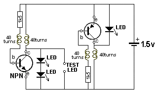
You fit an NPN or PNP transistor into one of the circuits with the leads around the correct way and the LED or LEDs will illuminate.
The 1k5 resistor limits the current into the base so the feedback winding can produce a voltage that adds to the supply voltage and turns the transistor ON harder to produce part of the cycle.
The operation of the circuit is quite complex because it involves the action of a transformer and this is always quite complex.
When current flows through a single turn of a coil, it produces magnetic flux and this flux flows around the wire so that it all comes out the centre of the turn. When more turns are added, the density of the flux increases as each turn adds more flux.
The supply for this project is from a battery and it produces flux called STATIONARY FLUX when a coil is connected to a voltage called a DC supply.
But when it is initially connected to a DC supply, the flux gradually builds up from zero to a maximum.
During this time the flux is called EXPANDING FLUX. This takes on a few microseconds to occur.
When the coil is removed from the DC supply, the magnetic flux collapses and it is called COLLAPSING FLUX.
Thus we can get 3 different types of flux from a DC supply.
When the flux collapses, it cuts all the turns of the coil and produces a voltage in each of the turns that is opposite to the applied voltage.
In addition, this flux collapses very quickly and the voltage produced is much higher than the applied voltage.
Finally, there is one more important fact you need to know about magnetic flux.
When the flux is expanding or collapsing, it cuts the turns of the other coil in the circuit and produces a voltage in the turns.
BUT when the flux is stationary, it does NOT produce any voltage in the other coil. It is only EXPANDING or COLLAPSING flux that induces a voltage in a second coil. The first coil is called the PRIMARY coil and the other coil is called the SECONDARY COIL or FEEDBACK coil.
This means the PRIMARY coil produces a voltage in the FEEDBACK WINDING when the PRIMARY is connected and when it is removed, but when it is fully connected and producing STATIONARY FLUX, the FEEDBACK WINDING is not producing any voltage.
This is the secret behind the operation of the transformer and you do not know the magnitude of the voltage produced by either of the coils until you build the project.
On top of this, you do not know how fast the circuit will oscillator until it is built. These are all characteristics of the coil, battery voltage, value of resistor, type of transistor, layout and many other things. We are not going onto any of this as you can see the result and measure the frequency.
The two coils of wire turns the circuit into a very complex arrangement that needs a high degree of understanding to see how it works. We will try to simplify everything by getting you to build the circuit and take measurements.
Two separate circuits are needed because an NPN transistor needs a positive voltage on the base while an PNP transistor needs a voltage that is less than the emitter.
Combining the two circuits would need a switch to change the positions of the coils and a coil of wire is simpler and cheaper to add to the PC board.
You can increase the brightness of the LED by placing a 100p to 4n7 across the 1k5 resistor. This changes the waveform from 8v to 7v but increases the frequency to more than 1MHz and the width of the spike is increased.
The capacitor effectively stops some of the spike being lost or being driven into the 1k5 resistor and now turns on the transistor more so a greater current flows. This current produces a healthier waveform when the coil collapses and delivers more energy to the LED.
The frequency increases because the transistor turns ON faster.
CONSTRUCTION
A kit of components is available from Talking Electronics.
All the components are included in the kit and everything is identified on the board.
The only fiddly job is making the two transformers.
This is the last job. Make sure all the other components are fitted to the board before making the coils.
Fit the NPN transistor to the board.
Wind 40 turns on a pen or shaft 12mm dia (0.5in) and make sure the shaft is tapered so the coil can be easily removed.
If the shaft is parallel, add a match or the lead of a resistor to the diameter and wind over this at the same time. Remove the wire and the coil will become lose and easily removed.
Before you remove the coil, twist the two ends together three times and cut the leads short.
Make 4 identical coils.
Place two coils on top of each other and keep them together by winding the 0.25mm wire around them as shown in the photo above.
Do not solder the ends of this wire together as this will produce a "shorted turn" and the transformer will not work.
Tin the 4 leads and fit two of the leads of one coil to the board.
Poke the other two leads down the holes in the board and the two LEDs should illuminate because the project is COMPLETE.
If the LEDs do not illuminates, reverse the two leads.
When the LEDs illuminates, you can solder them in position.
Carry out the same procedure with the PNP transistor.

Here is a photo of an NPN transistor fitted to the tester and
illuminating the red and green LEDs. The LEDs are very bright because
HIGH BRIGHT LEDs are included in the kit.
With these two LEDs illuminated, you can test an individual LED,
including white LEDs, by fitting it to the 2-pin component header in the
middle of the board. The two LEDs will go out and the LED under test
will illuminate when it is fitted around the correct way.

The cell is held tight by soldering two wires across the top and
bottom when it is in position.
No on-off switch is needed because the battery voltage is lower than the
voltage needed to activate any of the LEDs. The unused
cell-position on the board is designed for a AG12 cell, just in case you
do not have one of the very small AG1 or AG4 cells. Only 1 cell is
needed.
Transistor Tester |
|
2 - 1k5 resistors 2 - 3mm red LED 1 - 3mm green LED 4m - 0.1mm enamelled wire for coils 1 - 20cm 0.25mm enamelled wire around coils 2 - 3-pin machine pin sockets 1 - 3-pin component header 1 - NPN transistor 1 - PNP transistor 1 - button cell - AG1 or AG4 or AG12 1 10cm 0.5mm tinned copper wire 20cm very fine solder 1 - Transistor Tester PCB |
(buy a number of kits and pay
TEST
EQUIPMENT
Talking Electronics has a number of pieces of TEST EQUIPMENT to help in
the design and testing of projects.
Of course you can use a multimeter for most of the testing but some of
the "tricky" faults need a special piece of equipment.
You may only need a LOGIC PROBE once a month, but the project you are
designing will come to a
stand-still if you can't locate a problem.
We designed all these projects because we needed them ourselves.
Add one of them to each order you place with Talking Electronics and eventually you will have the whole
range.
LED TESTER
Tests LEDs.
$1.50 plus $4.00 post
(buy a number of kits and pay
only one postage)
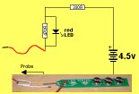
CONTINUITY TESTER
Only responds
to resistance less than 50 ohms.
Ideal for digital projects as it tests connections
very quickly.
$12.50 plus $6.50 post
(buy a number of kits and pay
only one postage)
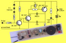
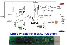
LOGIC PROBE with PULSER
- slimline
Detects HIGH and LOW
signals on both TTL and CMOS circuits.
The piezo allows you to hear low frequency signals
and the signal injector (Pulser) will over-ride
clock signals to make a circuit operate at a reduced
frequency.
$8.00 plus $6.50 post
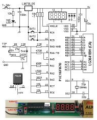
SUPER PROBE
20 different functions.
See article for the complete list of functions.
$18.00 plus $6.50 post
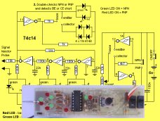
COMBO-2
TRANSISTOR TESTER
Tests transistors and shows the
gain of the transistor.
Also has Signal Injector probe.
$21.50 plus $6.50 post
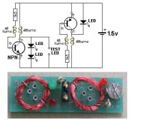
Simple
Transistor and LED Tester - 3
Tests PNP and NPN transistors and LEDs.
Also teaches the amazing property of an air-cored
coil in producing a high fly-back voltage.
$4.00 plus $3.00 postage.
(buy a number of kits and pay
only one postage)
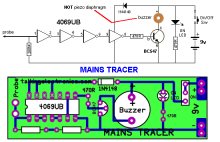
MAINS TRACER
Detects 240v AC mains hidden in walls etc.
Will also pick up RF signals from a keyboard to show you where
Electromagnetic Radiation is coming from and giving you a headache.
$10.00 plus $4.50 post
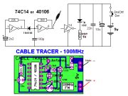
CABLE TRACER
- 100MHz
Traces cables when the power is OFF.
Uses an FM radio to pickup beeps.
$10.00 plus $4.50 postage.
only one postage)
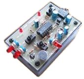
OP-AMP TRAINER and TESTER
Teaches how an op-amp works by using pots to control
the voltages on the two inputs.
$24.50 plus $6.50 post
(comes with instructions)
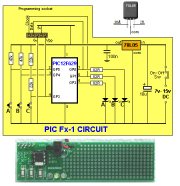
PIC Fx-1 MICRO (8 pin) PROGRAM DEVELOPER and TESTER
Learn to program PIC chips.
Comes with a pre-programmed PIC12F629 chip with 3 routines.
$12.00 plus $6.50 post
model railway
POINT MOTOR CONTROLLER and TESTER
CDU-Inline
The cheapest CDU project you can get.
$8.50 plus $6.50 post
