WHAT IS THE 555?
The 555 is an 8-pin chip that can be
turned into lots of
different things (building blocks).
The circuit inside the 555 is just an amplifier with 2 inputs and an
output.
The parts you add to the chip determine the final result (effect).
In most cases you add a capacitor and resistor to produce a circuit
known as a TIME DELAY CIRCUIT and the chip has a detection-pin and an
amplifier (also called a power amplifier) to produce an output.
It is not just a "timer," "delay" or "oscillator" but is capable of being
converted into these and maybe 100 other circuits.
Just call it the "555"
THE 555 IC
image from: Electronics Tutorials
THE 555 IC
The 555 HOW IT WORKS
To understand how the 555 works, you need to know
how to connect pins 2 and 6.
This is covered
HERE
Here is what you need to know:
Do not leave pins 2 and 6 un-connected. .
. . .the output of the 555 will be HIGH and sometimes it will be LOW.
Pins 2 and 6 are HIGH IMPEDANCE and can pick up static electricity and
sometimes turn the 555 on or off.
Here are the 4 possibilities for pins 2 and 6:
| Pin 2 LOW |
Pin 6 LOW |
Pin 3 HIGH |
Pin 2 controls the 555. Pin 6 has
NO effect. |
| Pin 2 LOW |
Pin 6 HIGH |
Pin 3 HIGH |
Pin 2
controls the 555. Pin 6 has NO effect. |
| Pin 2 HIGH |
Pin 6 LOW |
Pin 3
LOW |
Pin 2
controls the 555.(the 555 does not turn on) |
| Pin 2 HIGH |
Pin 6 HIGH |
Pin 3
LOW |
Pin 2
controls the 555. (the 555 does not turn on) |
| Connect pin 2 and 6 together.
Take both HIGH . . . ..
Pin 3
LOW (toggle Mode) |
| Connect pin 2 and 6 together.
Take both LOW . . . ..
Pin 3
HIGH (toggle Mode) |
Toggle Mode is also called
INVERTER MODE . . . The output is opposite to the input.
The 555 takes 10mA ALL THE TIME . . . even when the output is LOW
INTRODUCTION
This e-book
covers the 555.
The 555 is everywhere and it is one of the cheapest and most-rugged
chips on the market.
It comes as a TTL 555 and will operate from 4v to about 16-18v. (but don't
use less than 5.5v) It
costs from 10 cents (eBay) to $1.20 depending on the quantity and
distributor. The circuitry inside the chip takes about
10mA - even when the output is not driving a load. This means it is
not
suitable for battery operation if the chip is to be powered ALL THE
TIME.
The 555 is also available as a CMOS chip (ICM7555 or ICL7555 or TLC555)
and will operate from 2v to 18v and takes 60uA when the circuitry
inside the chip is powered. The "7555" costs from 60 cents (eBay) to
$2.00. But the output driving capability is a lot less than the
TTL 555.
We call the TTL version "555" and the CMOS version "7555."
This is called ELECTRONICS JARGON.
The 555 comes as a single timer in an 8-pin package or a dual timer
(556) in a 14 pin package.
The 7555 comes as a single timer in an 8-pin package or a dual timer
(7556) in a 14 pin package.
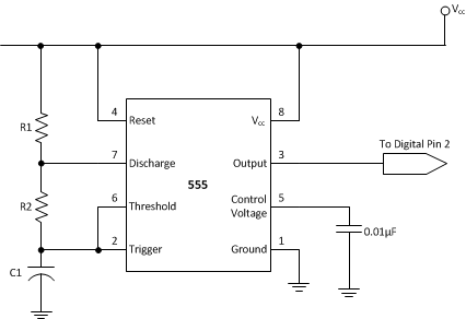
The 555 and 7555 are called TIMERS or Timer Chips. They contain about 28
transistors and the only extra components you need are called TIMING
COMPONENTS. This is an external resistor and capacitor. When a capacitor
is connected to a voltage, it takes a period of time to charge. If a
resistor is placed in series with the capacitor, the timing will
increase. The chip detects the rising and falling voltage on the capacitor.
When the voltage on the capacitor is 2/3 of the
supply the output goes LOW and when the voltage falls to 1/3, the output goes HIGH.
We can also do other things with the chip such as "freezing" or halting
its operation, or allowing it to produce a single HIGH-LOW on the output
pin. This is called a "ONE-SHOT" or MONOSTABLE OPERATION - but
it still takes 10mA while "sitting around".
When the chip produces an output frequency above 1 cycle per second,
(1Hz), the circuit is called an OSCILLATOR and below one cycle per
second, it is called a TIMER.
But the chip should not be called a "555 Timer," as it has so many applications.
That's why we call it a "555." (triple 5)
Another thing you have to be aware of is the voltage on output pin 3. It
is about 1-2v LESS THAN rail voltage and does not go to 0v (about 0.7v
for 10mA- output - and up to 1900mV for 200mA sinking current).
For instance, to get an output swing of 10v you will need a 12.6v
supply. In "electronic terms" the 555 has very poor sinking and
sourcing capabilities.
One way to understand how the chip operates is to remember that pin 7
goes LOW when pin 3 (the output pin) goes LOW. When pin 3 goes HIGH, pin
7 goes "open circuit" (it does not go HIGH - it goes HIGH IMPEDANCE).
When pin 4 is taken LOW, (it needs to be as low as 0.5v) the chip stops operating, but it still takes
10mA.
For photos of nearly every electronic component, see this website:
https://www.egr.msu.edu/eceshop/Parts_Inventory/totalinventory.php
You can also search the web for videos showing the 555 in
action.
Here are a few:
Making A 555 LED Flasher – Video Tutorial
Three 555 LED Flasher
555
Timer Flasher
Fading LED with 555 timer
Each website has lots more videos and you can see exactly
how the circuits work. But there is nothing like building the circuit
and that's why you need to re-enforce your knowledge by ACTUAL
CONSTRUCTION.
Learning Electronics is like building a model with Lego bricks. Each
"topic" or "subject" or "area" must be covered fully and perfectly, just
like a Lego brick is perfect and fits with interference-fit to the next
block. When you complete this eBook, you can safely say you will have
mastered the 555 - one more "building block" under your belt
and in the process you learn about DC motors, Stepper motors, servos, 4017
chips, LEDs and lots of other things. Any one of these can take you off
in a completely different direction. So, lets start . . .
Colin Mitchell
TALKING ELECTRONICS.
talking@tpg.com.au
To save space (and get everything on a single page) we have not provided lengthy explanations of how any of the
circuits work. This has already been covered in TALKING ELECTRONICS
Basic Electronics Course, and can be obtained on a
CD for $10.00
(posted
to anywhere in the world). See Talking Electronics website (http://www.talkingelectronics.com) for more
details on the 555 by clicking on the following
four pages:
555-Page 1
555-Page 2
555-Page 3
555-Test
Many of the circuits have been designed by Colin Mitchell:
Music Box,
Reaction Timer Game,
Traffic Lights,
TV Remote Control Jammer, 3x3x3 Cube,
while others are freely available on the web. But this eBook has brought
everything together and covers just about every novel 555 circuit. If
you think you know everything about the 555, take the
555-Test
and you will be surprised!
SI NOTATION
All the schematics in this eBook have components that are
labelled using the System International (SI) notation system. The SI
system is an easy way to show values without the need for a decimal
point. Sometimes the decimal point is difficult to see and the SI system
overcomes this problem and offers a clear advantage.
Resistor values are in ohms (R), and the multipliers are: k for kilo, M
for Mega. Capacitance is measured in farads (F) and the sub-multiples
are u for micro, n for nano, and p for pico. Inductors are
measured in Henrys (H) and the sub-multiples are mH for milliHenry and
uH for microHenry.
A 10 ohm resistor would be written as 10R and a 0.001u capacitor as 1n.
The markings on components are written slightly differently to the way
they are shown on a circuit diagram (such as 100p on a circuit and 101
on the capacitor or 10 on a capacitor and 10p on a diagram) and you will have to look on the internet under
Basic Electronics to learn about these differences.
Here's a 555 built from transistors by
Eric Schlaepfer in honor of
Hans Camenzined, who invented the 555:
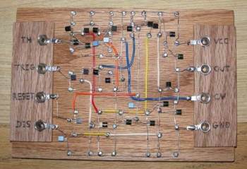
You can build your own 555 from this Instructable:
http://www.instructables.com/id/Build-Your-Own-555-Timer/
Or buy a kit for $35 from Evil Mad Scientist:
http://shop.evilmadscientist.com/productsmenu/tinykitlist/652

This kit is ideal for a school science project.
Here is the circuit and
assembly instructions.
WARNING!!
Before making any 555 project, remember the chip
takes about 10mA ALL THE TIME and cannot be turned off.
The output (the "driving power") of a 555 is about 200mA while
the CMOS versions are only about 50mA.
The chip is not really suited for doorbells and circuits as the 10mA will rapidly drain the battery.
The 555 does not like 5v supply. Use 6v
supply (minimum) when designing a circuit and then see if it
works on 5v. This is a REAL TRAP !!!!!
THE 555 IS RUBBISH
This headline is just to grab your attention.
There is one more problem with the 555. It is not suited to
deliver a current above 100mA on a 12v supply.
WHY?
This has never been covered before.
If you put a 555 on 12v and create a square-wave output (50:50)
with a load of 100R, the output voltage will be 10v and the
current will be 100mA when the output is HIGH and 0mA when the
output is LOW. This means the average current through the load
is 50mA. But the current taken by the circuit will be more than
50mA.
Where does the extra current go ????
It goes into the circuitry of the 555 and heats up the chip.
When the load is 50R, the current will be 200mA and 0mA with an
average of 100mA. But the current from the supply will heat up
the chip so hot that you cannot hold it.
Everyone thinks it is the loss of 2v due to the output
switching HIGH and LOW, but that would only account for about 400mW. The chip is
actually dissipating up to 1200mW and that's why it will burn
your finger.
The 555 was initially developed as a TIMER. It provides
time-delays up to about 30 minutes.
During a timing interval it might be able to deliver 200mA to a
load but when it is used as an oscillator, the transistors
inside the chip consume about 50% of the current and cause the
chip to heat up.
NOW YOU KNOW.
SURFACE MOUNT 555
The 555
is also available in SURFACE MOUNT packages.
 There
are 5 different sizes and you will need to find out the
"foot-print" before making a Printed Circuit board. There
are 5 different sizes and you will need to find out the
"foot-print" before making a Printed Circuit board.
All the features of the surface mount version are the same as
the through-hole version, but you must remember the output
does not "go to rail" or 0v. When the current through the output
pin is less than 10mA, the output will go as low as 250mV. But
when the current increases to 100mA to 200mA, the output will
not go lower than 2.5v.
When the output is HIGH and trying to deliver 200mA, it will be
2.5v lower than the supply voltage. That's why you need to make
a prototype circuit first and check the output voltage as well
as the heating of the chip. Max current is 200mA.
|
NEW!
FROM TALKING
ELECTRONICS
A new range of 555 chips have been designed by Talking Electronics to
carry out tasks that normally need 2 or more chips.
These chips are designated: TE 555-1, TE555-2 and the first project to
use the
TE 555-1 is STEPPER MOTOR CONTROLLER TE555-1.

It's a revolutionary concept. Instead of using an old 8-pin TTL
555 chip, you can use a new TE555-1,2,3 8-pin chip and save board
space as well as components. These new chips require considerably less
external componentry and the possibilities are endless. Depending on the
circuit, they can have a number of timing and frequency outputs as well as a
"power-down" feature that consumes almost no current when the circuit is
not operating. See the first project in this series: STEPPER MOTOR CONTROLLER TE555-1.
See also:
Stepper Motor Controller project
See also TE 555-2
TE555-3 TE 555-4
TE555-5
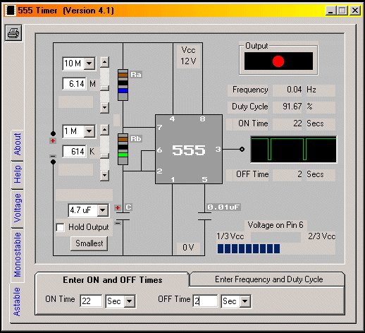
555 TIMER
CALCULATOR
A program to work out the values for a 555 in Astable or Monostable mode
is available from Andy Clarkson's website:
http://555-timer-circuits.uk/
555-Timer.zip
(987KB). Name a folder:
"555 Timer."
Unzip and run "555 Timer setup.exe"
Setup will produce a desktop icon. Click on icon for program. Set the
voltage for the 555 then use the Astable or Monostable tabs to design
your circuit. Read the Help screen to understand the operation of: "Hold
Output" and "smallest."
Here is another 555 calculator by
Jeff:
This calculator will provide a number of component values for the delay you want
or the frequency.
You can specify “10ms” or “4.5kHz” in the text fields.
| |