|
27MHz Transmitter 2 Channel |
|
|
One of the difficulties in building a 27MHz transmitter is the coil (transformer) used in the oscillator (transmitting) circuit.
Most circuits use a SLUG TUNED COIL (slug tuned transformer). This is a tapped coil wound on a former with a ferrite slug (or core) in the centre. This slug has a screw-thread so the inductance of the coil can be altered to set the frequency of transmission.
These slugs are impossible to obtain and this makes these circuits very difficult to build and impossible to produce as a kit.
The answer is to transfer the transformer (coil) to the underside of the PC board. This produces a fixed inductance so an air trimmer is needed to adjust the frequency of transmission.
This coil is quite successful and allows the project to be built on a small PC board.
We have gone further and added extra turns around the actual turns used in the transformer to gather the stray flux and pass it to the antenna. The 6 extra turns double the output and produce a benefit that no-one has done before. It's things like this that you can design and develop through experimentation.
These projects are only designed for short-range transmission and to show how to design a transmitter / receiver and how to tune a transmitter to a particular frequency.
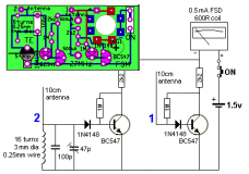
You will need the 27MHz FSM to show the transmitter is working and use the FSM to tune the transmitter to exactly 27MHz.
No on-off switch is needed as the circuit does not take any current when the switches are not pressed.
THE CIRCUIT
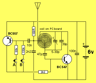
All oscillators needs POSITIVE feedback to maintain (start, and keep) oscillating.
You cannot connect the base to the collector on a common-emitter stage to produce an oscillator because a rise in voltage on the base causes the collector voltage to fall and any direct connection between the two will be NEGATIVE feedback and the circuit will never start to oscillate.
However the coil provides POSITIVE feedback.
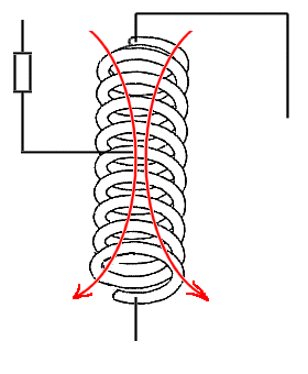
It works like this: The coil in the collector circuit is between the connection of the 100R and the collector. When this part of the coil has expanding flux, it passes this flux across the other turns in the coil and the centre of the coil has a voltage that is opposite to that on the collector.
In the following diagram we see the same coil.
This time it is in the form of "turns" but the same effect is produced with a printed circuit "flat" coil.
This is a VERY IMPORTANT concept to understand as it is very difficult to follow.
It is the same concept of the secondary of a centre-tapped power transformer where one end is positive and the other end is negative during one half of the waveform.
The coil in the diaphragm below has current flowing through the top half and it produces flux shown via the two red arrows. The heads of the arrows indicate the North pole but in our s case the flux is called EXPANDING FLUX.
In actual fact, the centre tap is called POSITIVE or RAIL and the top has a voltage less than rail as it is connected to the collector of the transistor and the transistor will be turn ON.
This means the bottom of the coil will produce a voltage HIGHER than rail and this voltage is an INCREASING voltage and is passed to the base to turn the transistor ON more.
The transistor gets turns ON more and more until it cannot be turned
ON any more.
At this point the expanding flux stops expanding and the pulse of energy
through the 47p stops. This is because a capacitor can only pass an
increasing or decreasing voltage. As soon as the voltage stops
increasing (or decreasing) the capacitor passes NOTHING.
The transistor suddenly stops receiving this increasing amount of energy
and it turns OFF.
The magnetic flux collapses and cuts all the turns with COLLAPSING flux
that produces a voltage in the opposite direction.
This puts a reverse voltage-pulse through the 47p to turn the base OFF
completely and counter-acts the current coming from the 2k2 resistor.
This it received a total of NOTHING.
The voltage (energy) from the coil charges the 39p and air trimmer and
these items take a certain amount of time to charge and they help
determine the frequency of oscillation.
We have added more turns around the outside of the coil to pick up the
stray magnetic flux and send it to the antenna. This doubles the output.
The PC coil and parallel capacitors combine to form a circuit classified
as a TANK CIRCUIT.
This is also known as a TUNED CIRCUIT but has the extra title of "Tank
Circuit" as it stores energy during part of the cycle and delivers it to
the antenna during the remainder of the cycle.
The coil also produces POSITIVE FEEDBACK to the transistor and has extra
turns called an "over-wind" to deliver extra voltage to the antenna. The
extra voltage produces (provides) extra amplitude and thus extra energy
to the antenna.
Extra energy produces extra range.
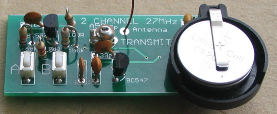
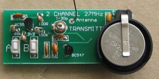
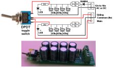
CONSTRUCTION
A kit of components is available from
Talking Electronics.
All the components are included in the
kit
and everything is identified on the board.
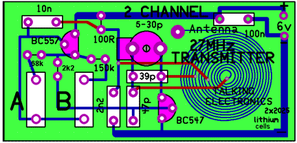
The layout of the
components on the PC board
27MHz
FSM |
|
1 - 100R
resistor
1 - 2k2 resistor 1 - 68k resistor 1 - 150k resistor 1 - 5 - 30p air trimmer 1 - 39p ceramic 1 - 47p ceramic 1 - 2n2 ceramic 1 - 10n ceramic 1 - 100n monoblock 1 - BC547 transistor 1 - BC557 transistor 2 - mini tactile switches 2 - 2032 coin cells or 2025 1 - coin cell holder 1 - 10cm 0.5mm wire for antenna 20cm very fine solder 1 - 27MHz Tx 2Ch PCB |
MORE TEST EQUIPMENT
Talking Electronics has a number of pieces of TEST EQUIPMENT to help in the design and testing of projects.
Of course you can use a multimeter for most of the testing but some of the "tricky" faults need a special piece of equipment.
You may only need a LOGIC PROBE once a month, but the project you are designing will come to a stand-still if you can't locate a problem.
We designed all these projects because we needed them ourselves.
Add one of them to each order you place with Talking Electronics and eventually you will have the whole range.
|
27MHz Field Strength Meter Tests 27MHz transmitters $6.50 plus $4.00 post Buy: 27MHz FSM kit |
 |
|
LED TESTER Tests LEDs. $1.50 plus $4.00 post (buy a number of kits and pay only one postage) |
 |
|
CONTINUITY TESTER Only responds to resistance less than 50 ohms. Ideal for digital projects as it tests connections very quickly. $12.50 plus $6.50 post (buy a number of kits and pay only one postage) |
 |
|
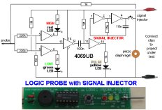
LOGIC PROBE with PULSER
- slimline Detects HIGH and LOW signals on both TTL and CMOS circuits. The piezo allows you to hear low frequency signals and the signal injector (Pulser) will over-ride clock signals to make a circuit operate at a reduced frequency. $8.00 plus $6.50 post |
 |
|
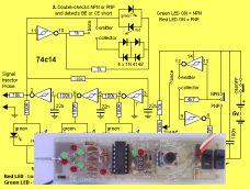
SUPER PROBE 20 different functions. See article for the complete list of functions. $18.00 plus $6.50 post |
 |
|
COMBO-2
TRANSISTOR TESTER Tests transistors and shows the gain of the transistor. Also has Signal Injector probe. $21.50 plus $6.50 post |
 |
|
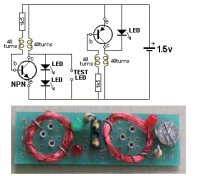
Simple
Transistor and LED Tester - 3 Tests PNP and NPN transistors and LEDs. Also teaches the amazing property of an air-cored coil in producing a high fly-back voltage. $4.00 plus $3.00 postage. (buy a number of kits and pay only one postage) |
 |
|
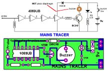
MAINS TRACER Detects 240v AC mains hidden in walls etc. Will also pick up RF signals from a keyboard to show you where Electromagnetic Radiation is coming from and giving you a headache. $10.00 plus $4.50 post |
 |
|
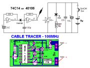
CABLE TRACER
- 100MHz Traces cables when the power is OFF. Uses an FM radio to pickup beeps. $10.00 plus $4.50 postage.
(buy a number of kits and pay |
 |
|
OP-AMP TRAINER and TESTER Teaches how an op-amp works by using pots to control the voltages on the two inputs. $24.50 plus $6.50 post (comes with instructions) |
 |
|
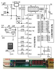
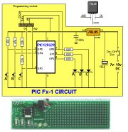
PIC Fx-1 MICRO (8 pin) PROGRAM DEVELOPER and TESTER Learn to program PIC chips. Comes with a pre-programmed PIC12F629 chip with 3 routines. $12.00 plus $6.50 post |
 |
|
model railway
POINT MOTOR CONTROLLER and TESTER
CDU-Inline The cheapest CDU project you can get. $8.50 plus $6.50 post |
 |