|
Make any 555 |
|
|
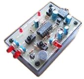
This handy circuit board allows you can make almost any 555 project.
The component markings on the board are not labelled so you can use values for your own design and the board is laid out exactly as a circuit diagram. This makes it easy to see where the components are placed.
It will help you get into electronics with your own "design-to-concept" project.
One of the difficulties in making a project is to convert a circuit into a layout on a PC board and this board overcomes the problem.
This is because the components are generally not placed in the same locations on the board, as on the circuit diagram. To make it more complex, the pinout of the chip does not correspond to the circuit.
We have changed that. The standard 555 circuit has been drawn on the board with the components placed in recognisable locations around the chip.
All you have to do is fit the components and the chip in an IC socket and connect the supply.
Some of the parts will have to be connected under the board with tinned copper wire.
This is much easier than using a matrix board or breadboard and you get a completed circuit, ready for connecting to a project, that looks like the REAL THING.
This universal board will not suit all circuits, but most of them can be adapted to fit.
You may have to cut some of the tracks and place some of the components in different places, but it will end up neat and professional.
You get 3 boards posted to anywhere in the world for $10.00 with a kit of parts for $5.00, all post FREE.
This is less than half the cost of buying the parts separately and is a real bargain.
The components on the board are in
the same places
as a circuit diagram.
HOW THE 555 WORKS
The way the 555 works is very hard to understand.
Here are the first 10 facts:
Pin 8 connects to the supply.
Pin 1 connects to 0v.
Pin 4 connects to the supply rail and the chip will work. When it is
taken to 0v, the chip will stop working. The chip will start working
when pin 4 is 0.7v or higher.
Pin 3 is the output pin.
It will deliver (source) 200mA to a LOAD and sink 200mA. But the chip
will get very HOT when doing this and so the output pin normally drives
a buffer transistor and the transistor drives the LOAD.
Pin 7 goes LOW when pin 3 goes LOW and pin 7 goes "open" when pin 3 goes
HIGH.
In other words, pin 7 will sink about 20mA but it will not SOURCE.
Pin 5 has 2/3 of the supply voltage on it and by changing the voltage on
this pin, the frequency of an oscillator can adjusted slightly.
An oscillator works by charging and discharging a capacitor via a
resistor.
When the frequency of an oscillator is higher than one cycle per second,
it is called an oscillator and the frequency is measured in cycles per
second (called Hertz).
When the frequency is less than one cycle per second, the oscillator is
called a TIMER or DELAY circuit. And the timing is measures in
seconds.
The 555 can be used as an OSCILLATOR or TIMER (Delay circuit).
It contains all the components to detect when the capacitor is charged
and when it is discharged.
It also charges and discharges the capacitor via one of the pins.
This pin is normally pin 7, but because pin 7 and pin 3 are LOW at the
same time, you have a choice of which pin to use.
The only pins left are pins 2 and 6.
A capacitor is added to the circuit with a series resistor.
These two components are called a TIMING CIRCUIT.
If we connect pins 2 and 6 to the join of these two components, the chip
will be able to detect when the capacitor is charged and when it is
discharged.
Pins 2 and 6 do not have any effect on the charging and discharging.
They are called HIGH IMPEDANCE pins or lines.
If we connect the TIMING CIRCUIT between the 0v rail and the supply
rail, the capacitor will charge.
To make it discharge we have to remove it from the supply rail and
connect the timing resistor to 0v.
That's what pin 7 does.
In one of the states, pin 7 effectively disappears and the capacitor
charges. In the other state, pin7 takes the charging resistor to 0v.
We need to add a resistor between pin 7 and the supply to allow Pin 7 to
do this.
The designer of the 555 chip allowed the capacitor to charge to 2/3 of
the voltage on the supply rail and pin 6 detects this level. He allowed
the capacitor to discharge to 1/3 of the voltage on the supply and pin 2
detects this level.
This has been done because the charging of a capacitor is not linear but
between 0 and 66% it is very linear.
This has been the simple explanation of how the 555 works.
It gets more complicated when you have a circuit that can have a high or
low voltage on pin 6 and at the same time a high or low voltage on pin
2.
PINS 2 AND 6
Now we come to the "first-in best-dressed" situation with pins 2 and 6.
Is there is an "over-ride" situation for these two pins? NO.
That's why you have to be very careful.
Pin 2 must be LOW to make the output HIGH
Pin 6 must be HIGH to make the output LOW.
Pin 2 has control over pin 6.
If neither pin is "controlling the chip" at start-up, what is the
output?
There are some circuits where Pin 6 is LOW and Pin 3 is HIGH, waiting
for an input to make it LOW.
In this situation no pin is sending a "set" or "reset"
message and the output can be either HIGH or LOW, depending on the
imbalances within the chip.
But for all the other cases, the output is known.
SET OR
RESET?
If pin 6 is HIGH and pin 2 is LOW - the
output will be HIGH - pin 2 is sending a "set" message
If pin 6 is HIGH and pin 2 is HIGH - the output will be LOW
- pin 6 is sending a "reset" message
If pin 6 is LOW and pin 2 is LOW - the output will be
HIGH - pin 2 is sending a "set" message
If pin 6 is LOW and pin 2 is HIGH - the output will be
HIGH or LOW - this is because no pin is sending a "set"
or "reset" message.
| Pin 2 | Pin 6 | Output pin 3 |
| HIGH | HIGH | LOW |
| HIGH | LOW | HIGH |
| LOW | HIGH | Unknown |
| LOW | LOW | HIGH |
This table is correct:
| Pin 2 | Pin 6 | Output pin 3 |
| HIGH | HIGH | LOW |
| HIGH | LOW | Unknown |
| LOW | HIGH | HIGH |
| LOW | LOW | HIGH |
THE CIRCUIT
The board can be wired to produce all sorts of 555 circuits,
including these:
BASIC 555 CIRCUITS
You can firstly make the circuit on breadboard and when it is operating correctly, transfer the parts to this PC board. Actually it is best to use a completely new set of parts, just in case you make a mistake and have to go back and locate the problem.
Whenever you are designing, building or making anything, you need to do things in small steps and stages so you can go back to a previous stage, if a fault develops.
This board is designed to reduce and remove frustration, so work slowly and double-check everything you do.
Designing a circuit is not easy and even copying a circuit from a book needs careful attention.
You need to know that the circuit works in the first place and you are not overloading the output of the chip or forgetting to connect any of the pins.
There are over 100 circuits on Talking Electronics website in the 50 - 555 Circuits folder and most of them can be modified and changed to suit different needs. But you need to build the original circuit first and change one value at a time. And the value must be changed in small steps. You cannot change 10k to 1M in some circuits as it will fail to work and if you do this with 3 components, you will never get the the result you expect. Only by checking each change, can you be sure the final circuit will work.
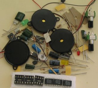
KIT OF PARTS:
|
The parts include: |
CONSTRUCTION
TEST
EQUIPMENT
(buy a number of kits and pay
A kit of components is available from
Talking Electronics
for $5.00
This will help you build almost any 555 circuit, and you get three 555
IC's.
Talking Electronics has a number of pieces of TEST EQUIPMENT to help in
the design and testing of projects.
Of course you can use a multimeter for most of the testing but some of
the "tricky" faults need a special piece of equipment.
You may only need a LOGIC PROBE once a month, but the project you are
designing will come to a
stand-still if you can't locate a problem.
We designed all these projects because we needed them ourselves.
Add one of them to each order you place with Talking Electronics and eventually you will have the whole
range.
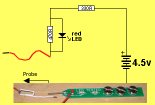
LED TESTER
Tests LEDs.
$1.50 plus $4.00 post
(buy a number of kits and pay
only one postage)
CONTINUITY TESTER
Only responds
to resistance less than 50 ohms.
Ideal for digital projects as it tests connections
very quickly.
$12.50 plus $6.50 post
(buy a number of kits and pay
only one postage)
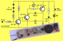
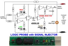
LOGIC PROBE with PULSER
- slimline
Detects HIGH and LOW
signals on both TTL and CMOS circuits.
The piezo allows you to hear low frequency signals
and the signal injector (Pulser) will over-ride
clock signals to make a circuit operate at a reduced
frequency.
$8.00 plus $6.50 post
SUPER PROBE
20 different functions.
See article for the complete list of functions.
$18.00 plus $6.50 post
COMBO-2
TRANSISTOR TESTER
Tests transistors and shows the
gain of the transistor.
Also has Signal Injector probe.
$21.50 plus $6.50 post
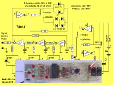
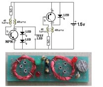
Simple
Transistor and LED Tester - 3
Tests PNP and NPN transistors and LEDs.
Also teaches the amazing property of an air-cored
coil in producing a high fly-back voltage.
$4.00 plus $3.00 postage.
(buy a number of kits and pay
only one postage)
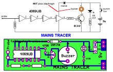
MAINS TRACER
Detects 240v AC mains hidden in walls etc.
Will also pick up RF signals from a keyboard to show you where
Electromagnetic Radiation is coming from and giving you a headache.
$10.00 plus $4.50 post
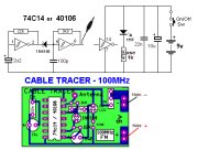
CABLE TRACER
- 100MHz
Traces cables when the power is OFF.
Uses an FM radio to pickup beeps.
$10.00 plus $4.50 postage.
only one postage)
OP-AMP TRAINER and TESTER
Teaches how an op-amp works by using pots to control
the voltages on the two inputs.
$24.50 plus $6.50 post
(comes with instructions)
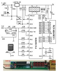
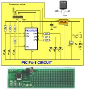
PIC Fx-1 MICRO (8 pin) PROGRAM DEVELOPER and TESTER
Learn to program PIC chips.
Comes with a pre-programmed PIC12F629 chip with 3 routines.
$12.00 plus $6.50 post
model railway
POINT MOTOR CONTROLLER and TESTER
CDU-Inline
The cheapest CDU project you can get.
$8.50 plus $6.50 post