|
DUAL |
|
|
Getting into Digital Control of two or more trains on the same layout can be fairly expensive as you need to buy an expensive COMMAND unit.
The loco's are slightly more expensive too, but once you have them, the command module will allow you to turn on lights, change crossing points, operate boom gates and control just about anything.
But what if you are just starting out?
This project starts you out with the ability to control 2 loco's on the same track.
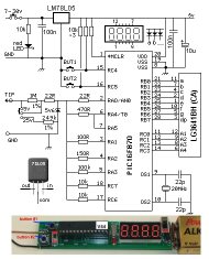
THE CIRCUIT
All the operation of the project is contained in an 8 pin
microcontroller.
The project will accept either 12v DC or 9v to12v AC.
The DC input is via separate terminals to avoid the loss of 0.6v + 0.6v from
the diodes. DO NOT USE BOTH INPUTS at the same time.
Use a 2 amp transformer to prevent a 1 amp transformer being overloaded.
DUAL DCC THROTTLE CIRCUIT
The project is designed to deliver up to 2 amps to the rails and this
will allow two trains to be operated at the same time.
2 THROTTLES
Throttle control knob 1 is on the main PC board. The second throttle
control knob needs
to be a short distance away from the main board so it can be operated by
a person with a clear view of the layout.
Use any type of twin flex to join the two boards - no current flows through
this.. Terminal A on
the main board is wired to terminal A on the smaller PC board. The kit
comes with 1.2 metres of twin flax.
POWER TO THE RAILS
The kit contains 2 alligator clips to clip onto the rails to allow you
to quickly deliver
current to operate the two trains.
The kit also contains a slim PC board that fits between the sleepers
with
two
Don't forget, you are delivering 1 or 2 amps.
Here is a photo of the track connectors:
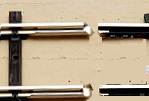
The voltage is supplied to the track via these rail joiners
THE POWER SUPPLY
The POWER SUPPLY is the item that connects to the project and
delivers either 12v DC or 9v to 12v AC.
It is usually a transformer with a set of 4 diodes and an electrolytic
(1,000u to 10,000u) contained in a box (or case) made from metal or
plastic.
This item converts the "Mains" (120v AC or 240v AC) to about 12v AC and
the 4 diodes are connected in a BRIDGE to change the alternating voltage
to DIRECT VOLTAGE and smoothed by the electrolytic.
These items are contained in a plastic box or metal case so you cannot
touch the 120v or 240v wires.
This is called insulation or isolation and makes it safe to have the
"mains" connected to the project.
The current required for this project is between 1 and 2 amps. The
actual current will be 1.1amps to 1.5 amps when both locos are
accelerating and since power supplies are rated at 1 amp or 2 amp, we
need to consider a 2 amp power supply.
A 2-amp power supply can be very expensive or very cheap.
We have written an article on producing a low-cost power supply and
you can read it
HERE.
OPERATION
The kit (and the fully built project) comes with a pre-programmed microcontroller with
addresses 3 and 5.
Address 3 will be on the remote PC board and 5 on the main PC board.
All loco's are purchased with address 3 in the locos memory and you normally
have to change this address so that two loco's do not clash.
If you are buying the Dual DCC Throttle kit and 2 Decoders,
they will be addresses: 3 and 5.
You can specify any address from 1 to 99 and the Throttle and Decoders
will be matched.
If you are buying 2 new loco's from your local Model Railway shop, you
will have to ask for one to be programmed to address 5.
FINDING YOUR LOCO ADDRESS
The program is slow to find the address but if it is within the range of say about: 1 to about 70, you will be able read the value from the flashing red LED. It will detect up to 255 locations, but this will take a long time to detect and a long time to read.
The "ADDRESS FINDING" chip is called "X" and is already fitted to the module. It is loaded with address 3 for the left-hand throttle and 5 for the right hand throttle. These are the two most common addresses and you should try the chip first.
A new loco ALWAYS has address 3 loaded into its memory and your unknown loco may still have this address.
These two addresses means you can drive a NEW loco from the left-hand throttle knob and a loco with address 5 from the right-hand throttle control knob (on the main PCB).
If you have a loco with an unknown address or an address other than 5, you can use the "X-chip" to locate the address.
If you have been provided with another chip for the module, make sure you change-over the chips very carefully with the white marking on the right-hand end of the chip - always keep it at the right-hand end - and the notch in the chip as shown on the overlay of the board. Lift the chip by placing a screwdriver under the chip and between the chip and the 8-pin socket - and lift it in a parallel-manner so the legs are not bent.
Here is the procedure:
With "X-chip" fitted:
Connect the output 2-screw terminal block, called: "TRACK" to a spare section of track (either way around) with the track connector provided in the package. The spare section of track must not be connected to any other part of your layout.
Place the loco on the track with buffers at each end.
Try both control knobs and if the loco does not move, you will have to find the address.
Turn the power off.
Click the FIND OFF slide switch to the left.
Push the FIND LOCO button and hold it down CONSTANTLY.
Now, connect the module to a 12v battery and the red LED on the right hand edge of the module will illuminate.
It will remain illuminated while the program slowly goes through each address and when it finds the loco address, the loco will start to move. This will tell the module that the loco has been found. Each address takes nearly a second to process.
The loco will drive for 1.5 seconds and stop.
At this point you immediately take your finger off the FIND LOCO button and the red LED will start to flash and you can count the flashes.
The number of flashes is the address for the loco and this has been added to EEPROM memory in the chip and will remain in memory after the chip has been turned off.
Remove the supply.
Click the FIND OFF slide switch to the right
Connect the supply.
The throttle knob on the main module will now drive the loco - forward and reverse.
If the motor does not run for 1.5sec and stop, the program has not detected the address. Turn the module off and wait 10 seconds and turn it ON again, by repeating the steps in the way described above, to get the program to respond correctly.
Dual DCC Throttle |
|
|
1 - 10R resistor 1 - 100R 2 - 330R 2 - 2k2 1 - 4k7 2 - 100k pots (throttle) 2 - knobs to suit 5 - 100n monoblock 1 - 10u 16v electrolytic 1 - 1,000u 25v electrolytic 10 - 1N4004 power diodes 2 - BC547 transistors 1 - 78L05 5v regulator 1 - PIC12F629 micro with "DCC" 1 - SN754410 IC 2 - 3mm red LED 5 - 2-way screw terminal blocks 1 - slide switch 1 - tactile switch 2 - alligator clips (for quick connection) 2 - rail connectors 1 - 8 pin IC socket 1 - 16 pin IC socket 20cm very fine solder
1 - Dual DCC Throttle PCB |
MORE TEST EQUIPMENT
Talking Electronics has a number of pieces of TEST EQUIPMENT to help in the design and testing of projects.
Of course you can use a multimeter for most of the testing but some of the "tricky" faults need a special piece of equipment.
You may only need a LOGIC PROBE once a month, but the project you are designing will come to a stand-still if you can't locate a problem.
We designed all these projects because we needed them ourselves.
Add one of them to each order you place with Talking Electronics and eventually you will have the whole range.
|
27MHz Field Strength Meter Tests 27MHz transmitters $6.50 plus $4.00 post |
 |
|
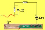
LED TESTER Tests LEDs. $1.50 plus $4.00 post (buy a number of kits and pay only one postage) |
 |
|
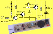
CONTINUITY TESTER Only responds to resistance less than 50 ohms. Ideal for digital projects as it tests connections very quickly. $12.50 plus $6.50 post (buy a number of kits and pay only one postage) |
 |
|
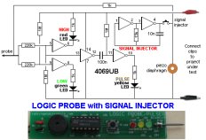
LOGIC PROBE with PULSER
- slimline Detects HIGH and LOW signals on both TTL and CMOS circuits. The piezo allows you to hear low frequency signals and the signal injector (Pulser) will over-ride clock signals to make a circuit operate at a reduced frequency. $8.00 plus $6.50 post |
 |
|
SUPER PROBE 20 different functions. See article for the complete list of functions. $18.00 plus $6.50 post |
 |
|
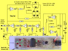
COMBO-2
TRANSISTOR TESTER Tests transistors and shows the gain of the transistor. Also has Signal Injector probe. $21.50 plus $6.50 post |
 |
|
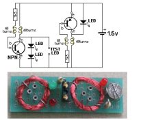
Simple
Transistor and LED Tester - 3 Tests PNP and NPN transistors and LEDs. Also teaches the amazing property of an air-cored coil in producing a high fly-back voltage. $4.00 plus $3.00 postage. (buy a number of kits and pay only one postage) |
 |
|
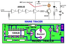
MAINS TRACER Detects 240v AC mains hidden in walls etc. Will also pick up RF signals from a keyboard to show you where Electromagnetic Radiation is coming from and giving you a headache. $10.00 plus $4.50 post |
 |
|
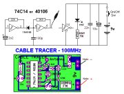
CABLE TRACER
- 100MHz Traces cables when the power is OFF. Uses an FM radio to pickup beeps. $10.00 plus $4.50 postage.
(buy a number of kits and pay |
 |
|
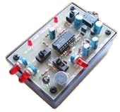
OP-AMP TRAINER and TESTER Teaches how an op-amp works by using pots to control the voltages on the two inputs. $24.50 plus $6.50 post (comes with instructions) |
 |
|
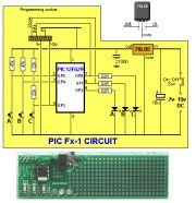
PIC Fx-1 MICRO (8 pin) PROGRAM DEVELOPER and TESTER Learn to program PIC chips. Comes with a pre-programmed PIC12F629 chip with 3 routines. $12.00 plus $6.50 post |
 |
|
model railway
POINT MOTOR CONTROLLER and TESTER
CDU-Inline The cheapest CDU project you can get. $8.50 plus $6.50 postt |
 |