SOLDERING THE KIT
Soldering these kits is very simple for me as I build them 10 at a time and have a very good soldering iron and 0.5mm solder THAT IS NOT CHINESE SOLDER. Do not use Chinese solder as it does not contain the correct percentage of tin and lead and it does not "run" or melt or flow properly and does not produce a shiny joint.
I can't use Chinese solder so you will definitely not be able to use it.
The first things you add to the board are the 13 surface mount resistors. Add a small amount of solder to one land for each resistor and pick them up with tweezers with the numbers showing and solder one end with the solder that is already on the land. Then go around and solder the other ends by adding a small amount of solder to each resistor.
The rest of the components are through-hole and it does not matter if you start at one end of the board or with the small components first.
Every component is identified on the board and most of the parts have to be fitted around the correct way - so look at the legend on the board.
The LEDs must be soldered very quickly otherwise they will be damaged.
The mark of a well-designed PCB is being able to put it together with a handful of parts and no other reference.
And the mark of a well-designed circuit is 100% operation with every board. You cannot afford to be messing around, "adjusting" the component values and trying to work out why it does not work.
That's why every value has a reason and a purpose. This can only be gained by working on hundreds of circuits and gaining the experience, knowledge and understanding.
The circuits are provided with all the projects to give you this experience.
And to help you fix something, if it "blows up."
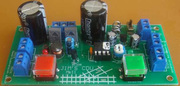
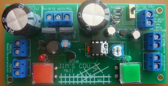
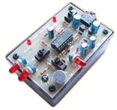
The photo's show the complete module. The electro's will be bent over and
laying flat above the top of the board, on modules pre-built and posted
through the mail as they are too tall for the post-box.
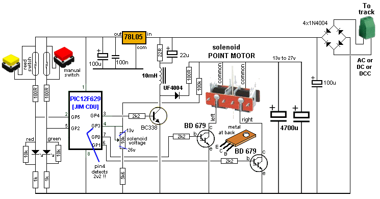
POWER CONNECTOR
OPERATION
The module cones wit.
Jim's
CDU MkII |
|
|
1 - 22R
surface mount 2 - 100R 1 - 220R 2 - 1k 3 - 2k2 1 - 5k6 2 - 10k 1 - 100k 1 - 100k mini trim pot 1 - 100n monoblock 1 - 22u 2 - 100u 2 - 4,700u 25v electrolytics 4 - 1N4004 power diodes 1 - UF4004 high speed 1amp diode 1 - 78L05 5v regulator 1 - BC338 2 - BD679 transistors 1 - PIC12F629 micro with "JimCDU" 1 - 3mm red LED 1 - 3mm green LED 5 - 2-way screw terminal blocks 1 - 3-way screw terminal block 1 - slide switch 2 - tactile switches 1 - 10mH choke 1 - 8 pin IC socket 20cm very fine solder 1 - Jim's CDU MkII PCB |
CONCLUSION
This is a very
interesting project to convert a solenoid operated point into
semi-automatic operation by adding the two reed switches that all
the train to set the point correctly when entering the point from
the opposite direction.
The module shows the position of the point and it's very easy
to set-up with the Power Connector and extension switches.
oooooooooooooo000000000000000000ooooooooooooooooo
TEST EQUIPMENT
Talking Electronics has a number of pieces of TEST EQUIPMENT to help in the design and testing of projects.
Of course you can use a multimeter for most of the testing but some of the "tricky" faults need a special piece of equipment.
You may only need a LOGIC PROBE once a month, but the project you are designing will come to a stand-still if you can't locate a problem.
We designed all these projects because we needed them ourselves.
Add one of them to each order you place with Talking Electronics and eventually you will have the whole range.
|
27MHz Field Strength Meter Tests 27MHz transmitters $6.50 plus $4.00 post |
 |
|
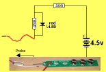
LED TESTER Tests LEDs. $1.50 plus $4.00 post (buy a number of kits and pay only one postage) |
 |
|
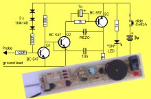
CONTINUITY TESTER Only responds to resistance less than 50 ohms. Ideal for digital projects as it tests connections very quickly. $12.50 plus $6.50 post (buy a number of kits and pay only one postage) |
 |
|
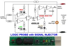
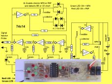
LOGIC PROBE with PULSER
- slimline Detects HIGH and LOW signals on both TTL and CMOS circuits. The piezo allows you to hear low frequency signals and the signal injector (Pulser) will over-ride clock signals to make a circuit operate at a reduced frequency. $8.00 plus $6.50 post |
 |
|
SUPER PROBE 20 different functions. See article for the complete list of functions. $18.00 plus $6.50 post |
 |
|
COMBO-2
TRANSISTOR TESTER Tests transistors and shows the gain of the transistor. Also has Signal Injector probe. $21.50 plus $6.50 post |
 |
|
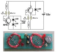
Simple
Transistor and LED Tester - 3 Tests PNP and NPN transistors and LEDs. Also teaches the amazing property of an air-cored coil in producing a high fly-back voltage. $4.00 plus $3.00 postage. (buy a number of kits and pay only one postage) |
 |
|
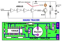
MAINS TRACER Detects 240v AC mains hidden in walls etc. Will also pick up RF signals from a keyboard to show you where Electromagnetic Radiation is coming from and giving you a headache. $10.00 plus $4.50 post |
 |
|
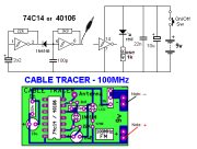
CABLE TRACER
- 100MHz Traces cables when the power is OFF. Uses an FM radio to pickup beeps. $10.00 plus $4.50 postage.
(buy a number of kits and pay |
 |
|
OP-AMP TRAINER and TESTER Teaches how an op-amp works by using pots to control the voltages on the two inputs. $24.50 plus $6.50 post (comes with instructions) |
 |
|
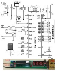
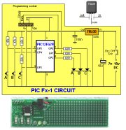
PIC Fx-1 MICRO (8 pin) PROGRAM DEVELOPER and TESTER Learn to program PIC chips. Comes with a pre-programmed PIC12F629 chip with 3 routines. $12.00 plus $6.50 post |
 |
|
model railway
POINT MOTOR CONTROLLER and TESTER
CDU-Inline The cheapest CDU project you can get. $8.50 plus $6.50 post |
 |