|
The |
This article is getting
larger and larger because nothing I am covering has ever been mentioned
before.
The whole idea of adding stages is to increase the amplitude of the
signal and its current-capability.
Eventually you will want the signal to drive a load and this will
require a large amplitude but most important is its current capability.
We can go from one microamp to 5 amp capability and this is 5,000,000:1
If a stage has a gain of 100, this will require a minimum of 4 stages.
But you cannot add stages without the high-energy output signal entering
the supply rail and passing back to the first stage where one or two
microvolts will enter the first stage and get amplified to produce a hum
or tone that cannot be prevented.
This is called MOTORBOATING or feedback
and is a major problem when you have more than 2 stages of
amplification.
We will now be up to 3 stage, from this 2-stage circuit:
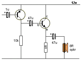
But first we have to convert the PNP stage into a self-biased arrangement:
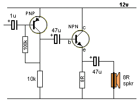
Adding the 100k will allow the PNP stage to
sit at mid-rail and give the output stage a fair chance of driving
full-scale.
You now have an input signal that can be based at the 0v rail and can be
as small as 1v, with a current-capability less than 0.1mA.
We have converted the LOAD requirement from 150mA and 12v amplitude into
2mA requirement at 12v amplitude via the output stage and the first
stage has changed the requirement from 2mA to 0.1mA and 1v amplitude.
No mathematics, no calculations, no transistor gain, no worries and no
frustration.
You just have to know what each stage does.
You need one more stage to connect an electret microphone as they
deliver about 20mV and less than 0.1mA.
Here is the pre-amplifier stage:
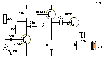
This circuit will produce a lot of
motorboating as the output is not separated (isolated) from the input.
Build it and see what we mean.
The 100u across the power supply will reduce the ripple from the output
stage>
SUMMARY
Page-1 Common-Emitter stage
Go to
Talking Electronics
website
9/9/2023
Two stages of separation are needed: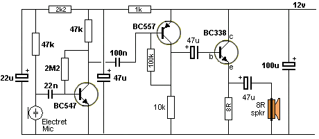
The1k and 47u will reduce the ripple on the supply rail from entering
the first stage.
The 2k2 and 22u will reduce ripple on the supply rail from entering the
electret microphone.
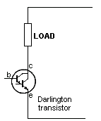
You may be tempted to use a Darlington transistor in the output as it
has a very high gain.
But there are two fact that you need to know.
Normally the data sheet for a Darlington transistor shows the gain to be
more than 1,000 and if you design the circuit around this value, you may
be in for a shock.
Sometimes the transistor will not perform successfully and it could be
due to the fact that the collector-emitter voltage drops to such a low
value that the base is equal or higher than the collector and the upper
transistor does not perform as a normal transistor. This means only the
lower transistor is working and the gain will be 100 to 200.
The other problem with Darlington transistors is the voltage across the
collector-emitter junction. It can be as high as 2v to 3v and the
transistor will get much hotter than expected. A normal output
transistor will have a collector-emitter voltage in the range 0.2v to 0.4v when
fully turned ON.
The electret microphone will produce a voltage-swing of about 10mV to
20mV and when this voltage is rising the electret mic is turning OFF and
the 47k is delivering the current to the first transistor stage.
You can work out the current or realise the output of the first stage is
also controlled by a 47k load resistor so the current from the electret
mic will not be increased very much but the voltage will be increased
from say 10mV to 3v. That's 300 times increase and you will have
to test the circuit to see if this occurs.
We now have the first stage capable of turning ON the second stage via
100n capacitor and we may get a swing of 6v to drive the
emitter-follower output stage. We will need about 2mA to do this and the
speaker will see almost twice this swing due to the effect of the 47u
connected to the output (as described previously).
The requirement is to build the circuit and measure the voltages with no input
signal. You can then adjust the component values to get the output you
want.
Notice: We have not used any mathematics, because it is quicker and
easier to change a component and get an actual result than waste time on
speculating.
Page1A. more on the stages
Page-2 emitter-follower - common collector stage
Page-2A common base stage
Page 3 Coupling stages
Page-5 The FLIP FLOP
Page-6 All the "YouTube" mistakes
The REAL
Transistor Amplifier