|
The |
I have
seen so many videos on YouTube with instructors following each other
with descriptions of how to design the stage.
Now we look at fitting different (wrong) value component to the output.
In fact ALL OF THEM ARE WRONG
You design the stage BACKWARDS.
The 3 critical components are the EMITTER RESISTOR, THE LOAD and the
OUTPUT CAPACITOR.
These 3 components will decide the output swing.
If the LOAD is directly coupled to the emitter, the circuitry is simple.
But when the output is coupled via a capacitor (electrolytic) the
output will be affected by the surrounding components.
What most instructors fail to take into account is the DISCHARGING of
the capacitor and the second cycle will fail to perform.
That's why taking only mathematics into the equation will give you a
failed design. You have to know how the circuit works to create
one that works.
An emitter-follower stage is also called a common collector
stage and it puts very little load on the stage that is driving it, and it
drives into a very low impedance load.
In other words it has a very high impedance input and a very low
impedance output.
The input needs to have an amplitude equal to rail voltage and only
requires about 1/100th the current into the load.
We say the transistor is a driver transistor and the stage is an
output stage. 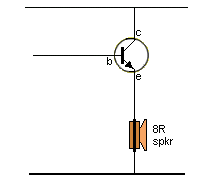 This is the ideal way to drive a LOAD. It is called
DIRECT
COUPLING.
When the base
is raised, the emitter follows with about 100 to 200 times more
strength.
You need a lot of "strength" (current) through the coil of the speaker
to move the cone and create a loud sound.
The circuit has NO LOSSES. There are no other components and thus
NO LOSSES.
If the input signal remains HIGH, full current will flow through the coil
of the speaker but it will not make any sound and just get hot. That's
the disadvantage of this circuit. The input must be oscillating at all
times.
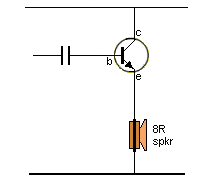 If
the input has the possibility of remaining HIGH, the
solution is to add a capacitor to the input. But it will introduce LOSSES. These
losses can be from 1% to 99%With the capacitor, the current flows through the coil of the speaker when the input
signal is rising and slightly less flows when the input signal is
falling.
If it stays HIGH, current will stop flowing through the coil of the
speaker because the capacitor will charge and the base voltage will drop
to almost zero.
This means you have full control of the current through the
voice-coil when the input signal is oscillating or when it is
stationary, and the speaker will never
get hot.
But you will have less control over the current when the signal is
falling. because the capacitor is charging and some of the amplitude of
the input signal is being lost.
When the next cycle is delivered, the capacitor is partially charged
because there is no component to discharge the capacitor. The base
emitter junction allows the capacitor to discharge to about 0.7v, but
this value remains on the capacitor. And the capacitor may not have time
to fully discharge due to the frequency of the input signal and an even
higher charge may be present.
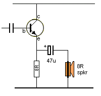 To
reduce these problems, this
is the next improvement to the circuit.
The speaker is now AC coupled to the output of the emitter-follower.
This means it is capacitor-coupled.
The load resistor is 8R, the speaker is 8R and a large capacitor is
added to transfer as much energy as possible.
The resistance (capacitive Reactance) of 47u at 2kHz is only 2 ohms and
it will have little effect on the transfer of energy.
Now we have a surprising advantage. The capacitor becomes a
miniature battery and it gets charged when the input
is rising and when the input falls, the positive lead of the 47u sees a
falling voltage and the other lead of the capacitor falls about the same
amount. This pushes a negative voltage through the voice coil and makes
the cone move in the opposite direction. All the energy in the 47u is
transferred to the speaker to produce a louder effect.
We have actually produced almost twice the amplitude of the signal into
the speaker.
This feature is so important that we will cover it in more detail.
Suppose the emitter is pulled HIGH. During this time the capacitor will
charge and the charging current will actually flow from the 0v rail and
up through the speaker to the capacitor. We have to describe it this way
so you understand what is happening. When the emitter is as high as
possible, the capacitor will be fully charged and the current through
the speaker will drop to zero.
The base voltage starts to fall and the transistor does not deliver as
much current through the 8R resistor. But the 47u is fully charged and
it is like a miniature battery. Replace it with a battery symbol to see
what is happening.
Suppose the 8R had 10 volts across it and the capacitor (battery) has
6v. The energy in the capacitor (battery) will start to flow through the
voice coil and as the voltage across the 8R resistor reduces, the
positive of the electrolytic starts to fall and and this makes the
negative lead fall and not only will it fall by the voltage in the
capacitor but by the 10v across the 8R. This current creates magnetic
flux in the opposite direction and pushes the cone in the opposite
direction and the speaker sees a waveform that is larger than the input
waveform.
Putting this phenomena another way, the charging current through the
speaker puts a positive on the top of the speaker. When the capacitor is
discharging, the speaker is effective "flipped over" and the top
terminal of the speaker is below the 0v rail and becomes negative. 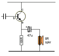
If we fit a high value resistor as the LOAD, This is what happens:
The output becomes a closed-loop with the capacitor as a battery and
passing current through 8R and 100R in series.
You can see the current will be a lot less than the circuit above where
the resistance is 16R.
But in the circuit above, the voltage across each component will be
about 50%. In this circuit the voltage across the speaker will be about
10%. So the energy will fall from 50% to 10%. This is called a
miss-match.
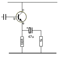 This
arrangement creates a miss-match because the circuit is required to deliver
a lot of current through the 100R load resistor, whereas the 1k is only
going to use 10% of the current.
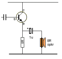
The coupling capacitor is too small. We said the 47u has a
capacitive reactance of 2 ohms. The 1u will be 100 ohms.
It will charge very quickly during a cycle and all the rise in voltage
from the transistor will be lost in the capacitor. The speaker will get
almost nothing.
And it will have very little energy to provide reverse voltage to the
speaker. The result will be absolutely zero output from the speaker.
INPUT IMPEDANCE OF THE EMITTER FOLLOWER STAGE
The input
impedance (resistance) of an emitter-follower stage is
about 100 times greater than the resistor connected to the emitter.
Basically we say it is the gain of the transistor. So, if the gain is
just 20, the input impedance will be 20 times greater.
Why worry about accurate figures when the transistor can alter
considerably with the current flow. You just have to know
approximately what to expect.
That's
why we say it puts very little load on the previous stage.
Don't forget, the previous stage is a MEDIUM CURRENT STAGE and has
DRIVING CAPABILITY.
The input capacitor has an effect on the maximum voltage into the emitter-follower stage.
The signal before the capacitor will be nearly rail voltage and the capacitor will charge slightly during the signal-rise and reduce the effect of the emitter-follower stage.
You don't need any complex mathematics but an understanding of how to work out approximate values.
We said 1u has a value of 100 ohms at the mid frequency we are amplifying and if the output is 100mA, the input will be about 1mA.
Doing a simple DC calculation of 1mA through 100R will produce a voltage of V=IR
= .001 x 100 = 0.1v In other words, the loss will be almost zero. All the AC calculations will be a lot less.
I am against doing complex calculations because the gain of the transistor may be 200 or as low as 50, and no calculations will get you closer to an actual value.
SUMMARY
You can see the output components have a very big effect on the transfer
of energy and the electrolytic actually improves the performance due to
it providing a REVERSE VOLTAGE.
Once you have worked out the necessary output components to provide the maximum transfer of
energy, you can decide on the type of driver transistor and the AC input
coupling capacitor.
None of this has ever been covered in any text books.
That's why all text books, University courses, YouTube channels and
demonstrations fail to mention these extremely important facts because
none of them have made, tested or fixed any of
the circuits they are talking about.
Emitter-follower circuits boil down to this: If the LOAD is in the
emitter, it will receive about 100 times more current than the value
supplied to the base. And the voltage across the load will be about
equal to the SUPPLY VOLTAGE.
If the load is coupled to the output with a capacitor, you will have to
test the circuit to see the amplitude of the voltage received by the
LOAD and how much "voltage doubling" you get from the output capacitor.
 A simple digital CRO costs less than $60.00 (built and tested) and will
save hours of wasted time calculating values you don't know.
Designing actually works in . . . REVERSE . . . .
BACKWARDS.
Page-1 Common-Emitter stage
Go to
Talking Electronics
website
9/9/2023
You can also think of it as working from BASICS - - -
WORKING from the START. Working from the BEGINNING. Working
from the ELEMENTS.
And only advancing very slowly in small steps and stages until the
project works perfectly .
That is how I design projects and modules that no-one else in the
world has designed. It looks simple in the end, but getting there is an
art.
It might take longer but it is the ONLY WAY.
Page1A more on the stages
Page-2A common base stage
Page 3 Coupling stages
Page 4 More on Coupling Stages
Page-5 The FLIP FLOP
Page-6 All the "YouTube" mistakes
The REAL
Transistor Amplifier