|
The |
THE
COMMON BASE AMPLIFIER
We have discussed the importance of matching the output impedance
of one stage to the input impedance of the next stage. When the two are
equal, the maximum energy is transferred and the losses are minimal. At
the same time you want a circuit that provides a very good
amplification-factor.
Suppose you want to match a very low resistance device (such as speaker
or coil) to the input of an amplifier. The speaker may be 8 ohms and the
input impedance of the common-emitter amplifiers we have described is
about 500R to 2k. The two can be connected via a capacitor but we have
already mentioned how a capacitor transfers only a small amount of
energy when the two impedances are not equal. And when the two
impedances are so mismatched as 8:2,000, the transfer may be very poor.
The answer is to use a stage that has a very low input impedance and a
high output impedance.
That's a COMMON BASE amplifier.
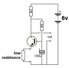
Here is a COMMON BASE amplifier:

COMMON BASE amplifier
A
common-base amplifier is identified by the base "tied" to
the 0v rail. We say "tied" (connected) to the 0v rail as far
as the signal on the base will not be allowed to rise and fall. The
actual voltage on the base may be higher than zero volts, but this
voltage will change.
The common-base amplifier (Common-Base stage) accepts a
low value of resistance on the input and produces a high gain. Since the
input is directly coupled to the transistor, there are no losses.
We have already mentioned two ways to turn ON an NPN transistor.
1. Hold the emitter fixed and RAISE the base voltage.
2. Hold the base fixed and LOWER the emitter voltage.
We are using the second option. The base is held rigid (as far as
signals are concerned) and any rise or fall in voltage on the emitter
appears on the collector with a voltage increase.

Dynamic
Microphone
See this article and return
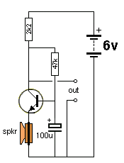
This circuit
converts an ordinary speaker into a very sensitive microphone.
The fact that the load resistor is (a low) 2k2, means the stage has a
good capability of delivering energy to the next stage.
We have already discussed the fact that the "load" resistor determines
the capability of the stage to pass energy to the next stage.
Here are the details of the gain to expect from the stage:
The impedance of the speaker is 8 ohms. The 2k2 and 47k resistors are
designed to put 3v on the collector. This means 3/2,200mA will flow in
the 2k2 (1.3mA). This current will also flow in the 8R speaker voice
coil.
Suppose we generate a voltage of
1mV from the speaker. This voltage will produce an extra 1/8mA in the
emitter-line. [from Ohm's Law:
The collector current is almost the same as the emitter-current and now the additional 0.125mA will REDUCE the collector current and the change across the 2k2 will be 2,200/8 = 275mV. Thus the collector voltage will RISE 275mV. Thus the gain of the circuit is 275.
We are already assuming the voltage on the collector is 3v and the 47k has been selected to create this 3v. Taking the circuit as a whole, the collector can increase by 2.75v and decrease by 2.75 before clipping occurs (because we have 3v available) and thus the speaker can produce a 20mV p-p before clipping. (because 20mV will produce a voltage of 275mV x 20 = 5.5v on the collector = 2.75v increase and 2.75v decrease.) And the gain of the transistor does not come into the calculation.
The cone will produce a waveform in the opposite direction during the second half of the cycle and the collector will FALL 275mV or 2.75v according to the mV produced by the speaker.
No-one has ever described this critical feature and unless you know what is occurring, you cannot interpret a trace on a DIGITAL oscilloscope.

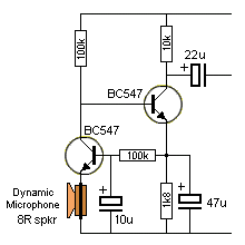
Common Base and Common Emitter
stages directly coupled together
This circuit adds a Common Emitter stage to the Common Base to produce a DC coupled (Directly Coupled) amplifier with very high gain.
The common-emitter transistor can be called a BUFFER stage as it provides a lower impedance output than the first stage.
THE BOOTSTRAP CIRCUIT
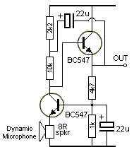
 Another very interesting circuit is the Bootstrap Circuit.
The output of the second transistor has been taken
back to its input to produce an improvement called a
BOOTSTRAP Circuit
to create an even higher gain. It uses positive feedback
to achieve this very high gain.
 The two transistor circuit shown above has a gain of approx 1,000 and converts the very low output of the speaker into a waveform that can be fed into an amplifier.
The circuit is simply a common-base stage and an emitter-follower stage.
But the output of the emitter-follower is taken back to the input of the same stage and this is the Bootstrap feature. It is like pulling yourself UP by pulling your shoe laces.
When the voltage from the speaker reduces by 1mV, the transistor turns ON a little more and pulls the collector voltage lower.
This action takes a lot of effort and to pull it lower, requires more energy from the speaker.
In the Bootstrap circuit, the common-base transistor pulls the 10k down and this pulls the emitter-follower transistor down. At the same time the upper 22u is pulled down and it pulls the 10k down to assist the first transistor. In other words the first transistor finds it much easier to pull the 10k resistor down.
When the common-base transistor turns off, the 2k2 pulls the 10k resistor UP and it is aided by the top 22u. The end result is a very high output voltage swing.
The loud speaker will detect a pin drop and it will become a very sensitive microphone.
You can use the circuit for a low impedance transducer such as a coil. These are normally very difficult to interface.
Page-1 Common-Emitter stage
Page1A more on the stages
Page-2 emitter-follower - common collector stage
Page-2A common base stage - this page
Page 3 Coupling stages
Page 4 More on Coupling Stages
Page-5 The FLIP FLOP
Page-6 All the "YouTube" mistakes
The REAL
Transistor Amplifier
Go to
Talking Electronics
website
19/2/2024