INTRODUCTION
This e-book
covers the Light Emitting Diode.
The LED (Light Emitting Diode) is the modern-day equivalent to the
light-globe.
It has changed from a dimly-glowing indicator to one that is
too-bright to look at.
However it is entirely different to a "globe."
A globe is an electrical device consisting of a glowing wire while a LED is an electronic device.
A LED is more efficient, produces less heat and must be "driven"
correctly to prevent it being damaged.
This eBook shows you how to connect a LED to a circuit plus a number of
projects using LEDs.
It's simple to use a LED - once you know how.
INSIDE A LED:
A "Natural" or "Characteristic" voltage develops across a
LED when it is correctly connected in a circuit with a current-limiting
resistor to allow a current between 1mA and 20mA. This voltage is
shown in the table above and we normally use the lower value for each
colour. However the table shows the voltage varies quite a lot and this
depends on the actual crystalline construction of the crystal and the
way it is manufactured. You cannot change this and that's why you need
to measure the voltage across the LED when building some of the
circuits.
LED VOLTAGES
Here is another table showing
LED Voltages. The voltage across a LED depends on the manufacturer, the
intensity of the colour and the actual colour.
LED VOLTAGES depend on many factors. You
must
test the LED(s) you are using.
The voltage across some LEDs increases by 500mV (0.5v) when the current
increases from about 10mA to 25-30mA and if you have 6 LEDs in series,
this is an increase of 3v. If you are using a 12v supply, you cannot
(should not) put 4 white LEDs in series as the "characteristic voltage
will be 3.6 x 4 = 14.4 and this is higher than the voltage from a 12v
battery. You will need
to remove one LED and fit a resistor to get the brightness you require.
BUYING LEDs
The brightness of a LED is
very difficult to understand. They come in outputs from 15mcd to
100,000mcd and require from 1mA to more than 300mA.
The only way to add a LED to a project is to buy all sorts of different
LEDs and test each one for suitability.
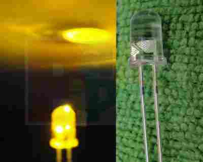
LEDs can be too bright for an application and will "wash out" your eyes
when the light from the LED is viewed directly. This is especially
severe with clear LEDs as the beam is not diffused. Diffused LED
have a case of the same colour as the light and will "glow."
For instance 3mm green LEDs come in a wide range.
The weakest is 16mcd to 80mcd
Standard green is 140mcd
High bright green is 1,200mcd
Super Bright green is 8,000mcd
Aliexpress has green LEDs at the lowest cost. 1,000 pcs for
$9.00 200 to 400mcd
1,000 pcs for $9.00 400 to 600mcd
You should start by buying mixed LEDs of 5 colours and you will be
surprised at the quality and price for 500 mixed.
CONNECTING A LED
A LED must be connected around
the correct way in a circuit and it must have a resistor to limit the
current.
The LED in the first diagram does not illuminate because a red LED
requires 1.7v and the cell only supplies 1.5v. The LED in the second
diagram is damaged because it requires 1.7v and the two cells supply 3v.
A resistor is needed to limit the current to about 25mA and also the
voltage to 1.7v, as shown in the third diagram. The fourth diagram
is the circuit for layout #3 showing the symbol for the LED, resistor and battery and
how the three are connected. The LED in the
fifth diagram does not work because it is around the wrong way.
CHARACTERISTIC VOLTAGE DROP
When a LED is connected around the correct way in a circuit it
develops a voltage across it called the CHARACTERISTIC VOLTAGE DROP.
A LED must be supplied with a voltage that is higher than its
"CHARACTERISTIC VOLTAGE" via a resistor - called a VOLTAGE DROPPING
RESISTOR or CURRENT LIMITING RESISTOR - so the LED will
operate correctly and provide at least 10,000 to 50,000 hours of
illumination.
A LED works like this: A LED and resistor are placed in series
and connected to a voltage.
As the voltage rises from 0v, nothing happens until the voltage reaches
about 1.7v. At this voltage a red LED just starts to glow. As the
voltage increases, the voltage across the LED remains at 1.7v but the
current through the LED increases and it gets brighter.
We now turn our attention to the current though the LED. As the
current increases to 5mA, 10mA, 15mA, 20mA the brightness
will increase and at 25mA, it will be a maximum. Increasing
the supply voltage will simply change the colour of the LED slightly but
the crystal inside the LED will start to overheat and this will reduce the life
considerably.
This is just a simple example as each LED has a different CHARACTERISTIC
VOLTAGE DROP and a different maximum current.
In the diagram below we see a LED on a 3v supply, 9v supply and 12v
supply. The current-limiting resistors are different and the first
circuit takes 6mA, the second takes 15mA and the third takes 31mA. But
the voltage across the red LED is the same in all cases. This is because
the LED creates the
CHARACTERISTIC VOLTAGE DROP
and this does not change.
It does not matter if the
resistor is connected above or below the LED. The
circuits are the SAME in operation:
HEAD VOLTAGE
Now we turn our attention to the resistor.
As the supply-voltage increases, the
voltage across the LED will be constant at 1.7v (for a red LED) and the excess voltage
will be dropped across the resistor. The supply can be any voltage from
2v to 12v or more.
In this case, the resistor will drop 0.3v to 10.3v.
This is called HEAD VOLTAGE - or HEAD-ROOM or OVERHEAD-VOLTAGE.
And the resistor is called the CURRENT-LIMIT resistor.
The following diagram shows HEAD VOLTAGE:
The voltage dropped across this resistor, combined with the current,
constitutes wasted energy and should be kept to a minimum, but a small
HEAD VOLTAGE is not advisable (such as 0.5v). The head voltage should be a minimum of
1.5v - and this only applies if the supply is fixed.
The head voltage depends on the supply voltage. If the supply is fixed
and guaranteed not to increase or fall, the head voltage can be small
(1.5v minimum).
But most supplies are derived from batteries and the voltage will drop
as the cells are used.
Here is an example of a problem:
Supply voltage: 12v
7 red LEDs in series = 11.9v
Dropper resistor = 0.1v
As soon as the supply drops to 11.8v, no LEDs will be illuminated.
(Sometimes the LEDs will illuminate because some LEDs will have a
characteristic voltage that is slightly less than 1.7v and some will
illuminate when the voltage is lower than 1.6v - but the brightness will
reduce considerably.)
Example 2:
Supply voltage 12v
5 green LEDs in series @ 2.1v = 10.5v
Dropper resistor = 1.5v
The battery voltage can drop to 10.5v
But let's look at the situation more closely.
Suppose the current @ 12v = 25mA.
As the voltage drops, the current will drop.
At 11.5v, the current will be 17mA
At 11v, the current will be 9mA
At 10.5v, the current will be zero
You can see the workable supply drop is only about 1v.
Many batteries drop 1v and still have over 80% of their energy
remaining. That's why you need to design your circuit to have a large
HEAD VOLTAGE.
A large Head Voltage is also needed when a plug-pack (wall
wart) is used. These devices consist of a transformer, set of diodes and
an electrolytic. The voltage marked on the unit is the voltage it will
deliver when fully loaded. It may be 200mA, 300mA or 500mA. When this
current is delivered, the voltage will be 9v or 12v. But if the current
is less than the rated current, the output voltage will be higher. It
may be 1v, 2v or even 5v higher.
This is one of the characteristics of a cheap transformer. A cheap
transformer has very poor regulation, so to deliver 12v @ 500mA, the
transformer produces a higher voltage on no-load and the voltage drops
as the current increases.
You need to allow for this extra voltage when using a plug-pack so the
LEDs do not take more than 20mA to 25mA.
Roger Mew contacted me asking for some suitable resistances for the HEAD
VOLTAGE resistor.
Here is a list:
For 25mA current:
Use 56R for 1.5v drop.
Use 82R for 2v drop
Use 120R for 3v drop
Use 150R for 4v drop
Use 180R for about 5v drop
TESTING A LED
If the cathode lead of a LED cannot be identified, place 3 cells in series with a 220R
resistor and illuminate the LED. 4.5v allows all types of LEDs to
be tested as white LEDs require up to 3.6v. Do not use a multimeter as some only
have one or two cells and this will not illuminate all types of LEDs. In
addition, the negative lead of a multimeter is connected to the positive of the cells
(inside the meter)
for resistance measurements - so you will get an incorrect determination
of the cathode lead.

CIRCUIT TO TEST ALL TYPES OF LEDs
including blue and white
IDENTIFYING A LED
A LED does not have a "Positive" or "Negative" lead. It has a lead
identified as the "Cathode" or Kathode" or "k". This is identified by a
flat on the side of the LED and/or by the shortest lead.
This lead goes to the 0v rail of the circuit or near the 0v rail (if the LED is connected to other components).
Many LEDs have a "flat" on one side and this identifies the cathode.
Some surface-mount LEDs have a dot or shape to identify the
cathode lead and some have a cut-out at one end.
Here are some of the identification marks:

Note: the 3 leaded LED is different. The flat indicates the red LED and
the other LED is green. See the diagram for the placement of the two
LEDs.
LEDs ARE CURRENT-DRIVEN DEVICES
A LED is described as a CURRENT DRIVEN DEVICE. This means the
illumination is determined by the amount of current flowing through it.
This is the way to see what we mean: Place a LED and 100R resistor in
series and connect it to a variable power supply.
As the voltage is increased from 0v, to 1v, the LED will not produce any
illumination, As the voltage from the power-supply increases past 1v,
the LED will start to produce illumination at about 1.6v to 1.7v (for a
red LED). As the voltage is increased further, the illumination
increases but the voltage across the LED does not increase. (It may
increase 0.1v) but the brightness will increase enormously. That's why
we say the LED is a CURRENT DRIVEN DEVICE.
The brightness of a LED can be altered by increasing or decreasing the
current. The effect will not be linear and it is best to experiment to
determine the best current-flow for the amount of illumination you want.
High-bright LEDs and super-bright LEDs will illuminate at 1mA or less,
so the quality of a LED has a lot to do with the brightness. The life of many LEDs is determined at
17mA. This seems to be the best value for many types of LEDs.
1mA to 5mA LEDs
Some LEDs will produce illumination
at 1mA. These are "high Quality" or "High Brightness" LEDs and the only
way to check this feature is to test them @1mA as shown below.
THE 5v LED
Some suppliers and some websites talk about a 5v
white or blue LED. Some LEDs have a small internal resistor and can be
placed on a 5v supply. This is very rare.
Some websites suggest placing a white LED on a 5v supply. These LEDs
have a characteristic voltage-drop of 3.6v and should not be placed
directly on a voltage above 3.6v. If placed on a voltage below 3.6v, the
LED will not glow very brightly. If you have a voltage EXACTLY 3.6v, you
can connect the LED, but most voltages are higher than 3.6v and thus you
need a resistor.
The only LED with an internal
resistor is a FLASHING LED. These LEDs can be placed on a supply from
3.5v
to 12v and flash at approx 2Hz. The LED is very weak on 3.5v but its
flashing can be used to drive a powerful LED (see circuits section). It
can also be used to produce a beep for a beeper FM transmitter.
NEVER assume a LED has an internal resistor. Always add a series
resistor. Some high intensity LEDs are designed for 12v operation. These
LEDs have a complete internal circuit to deliver the correct current to
the LED. This type of device and circuitry is not covered in this eBook.
If you don't know if a resistor is inside the device (such as a LED
strip) you are testing, add a 100R and connect to a 12v supply.
Measure the current and if it less than expected, you can reduce the
resistor to 47R and then 10R or remove it.
Putting a LED on a high voltage will instantly destroy it and a 100R
will prevent it being damaged.
LEDs IN SERIES
LEDs can be placed in
series providing some features are taken into account. The main item to
include is a current-limiting resistor.
A LED and resistor is called a string. A string can have 1, 2, 3 or more
LEDs.
Three things must be observed:
1. MAXIMUM CURRENT through each string = 25mA.
2. The CHARACTERISTIC VOLTAGE-DROP must be known so the correct
number of LEDs are used in any string.
3. A DROPPER RESISTOR must be included for each string.
The following diagrams show examples of 1-string, 2-strings and 3-strings:

LEDs IN
PARALLEL
LEDs
CANNOT be placed in parallel - until you read this:
LEDs "generate" or "possess" or "create" a voltage across them called
the
CHARACTERISTIC VOLTAGE-DROP
(when they are correctly placed in a circuit).
This voltage is generated by the type of crystal and is different
for each colour as well as the "quality" of the LED (such as
high-bright, ultra high-bright etc). This characteristic cannot be
altered BUT it does change a very small amount from one LED to another
in the same batch. And it does increase slightly as the current
increases.
For instance, it will be different by as much as 0.2v for red LEDs and
0.4v for white LEDs from the same batch and will increase by as much as
0.5v when the current is increased from a minimum to maximum.
You can test 100 white LEDs @15mA and measure the CHARACTERISTIC
VOLTAGE-DROP to see this range.
If you get 2 LEDs with identical
CHARACTERISTIC VOLTAGE-DROP,
and place them in parallel, they will each take the same current. This
means 30mA through the current-limiting resistor will be divided into
15mA for each LED.
However if one LED has a higher
CHARACTERISTIC VOLTAGE-DROP,
it will take less current and the other LED will take considerably more.
Thus you have no way to determine the "current-sharing" in a
string of parallel LEDs. If you put 3 or more LEDs in parallel,
one LED will start to take more current and will over-heat and you will
get very-rapid LED failure. As one LED fails, the others will take
more current and the rest of the LEDs will start to self-destruct. The
reason why they take more current is this: the current-limit resistor
will have been designed so that say 60mA will flow when 3 LEDs are in
parallel. When one LED fails, the remaining LEDs will take 30mA each.
Thus LEDs in PARALLEL should be avoided.
Diagram A below shows two green LEDs
in parallel. This will work provided the Characteristic Voltage Drop
across each LED is the same.
In diagram B the Characteristic
Voltage Drop is slightly different for the second LED and the first green LED will glow
brighter.
In diagram C the three LEDs have
different Characteristic Voltage Drops and the red LED will glow very
bright while the other two LEDs will not illuminate. All the current
will pass through the red LED and it will be damaged.
The reason why the red LED will glow very bright is this: It has the
lowest Characteristic Voltage Drop and it will create a 1.7v for the three
LEDs. The green and orange LEDs will not illuminate at this voltage and
thus all the current
from the dropper resistor will flow in the red LED and it will be
destroyed.
THE RESISTOR
The value of the current limiting resistor can be worked out by Ohms
Law.
Here are the 3 steps:
1. Add up the voltages of all the LEDs in a string. e.g:
2.1v + 2.3v + 2.3v + 1.7v = 8.4v
2. Subtract the LED voltages from the supply voltage. e.g:
12v - 8.4v = 3.6v
3. Divide the 3.6v (or your voltage) by the current through the string.
for 25mA: 3.6/.025 =144 ohms
for 20mA: 3.6/.02 = 180 ohms
for 15mA: 3.6/.015 = 250 ohms
for 10mA: 3.6/.01 = 360 ohms
This is the value of the current-limiting resistor.
Here is a set of strings for a supply voltage of 3v to 12v and
a single LED:
Here is a set of strings for a
supply voltage of 5v to 12v and a white LED:
Here is a set of strings for a
supply voltage of 5v to 12v and two LEDs:
CONNECTING A STRING OF LEDs
Connecting 2, 3 or 4 or more LEDs to a voltage is easy. But you must
follow these simple instructions:
A LED circuit is designed around
VOLTAGE.
This is the first thing you have to provide. You need to provide
a voltage that is greater than the characteristic voltage of the LED or
LEDs in the circuit (called a "string").
This voltage will be at least 1.7v for a red LED and about 3.6v to 3.8v
for a white LED. The voltage for each colour LED is discussed above.
If you have more than one LED in the circuit, you need to add these
"characteristic voltages."
Suppose you get 3 x 3.8v = 11.4v for three white LEDs.
This is called the EXACT VOLTAGE you need to deliver. If you
deliver 11v, none of the LEDs will illuminate.
If you deliver 11.8v, all the LEDs will be extremely bright and will
burn out in a few minutes or hours.
LEDs are not torch globes.
They are nothing like torch globes.
So, you cannot think of them as torch globes.
They are an ELECTRONIC device. They do not have a hot wire inside
them that glows.
They have a crystal that illuminates when a current flows from one
contact, through the crystal to the other contact.
When the LED illuminates, you know the voltage that will develop across
the leads, by looking at the colour produced and then looking at the
table above.
BUT you do not know the current required by the LED.
The normal current is 17mA to 20mA, but some high-bright LEDs will
produce very good brightness at 10mA or even 1 to 5mA.
You need to find out how much current you want to flow through the
string of LEDs.
It might be low to conserve battery life or high to produce the maximum
brightness.
If you have a string of LEDs, the current flowing through the first LED
will be same as all the other LEDs and this may produce different
illumination if the LEDs are from different manufacturers or of
different quality.
The final step is to add a resistor to illuminate them. This is called
the CURRENT LIMITING RESISTOR.
You can find the value of this resistor by mathematics, but this is
pointless when you dont know the current required by the string. And the
current can be anywhere from 1mA to 30mA.
You need to have a supply that is at least 1v higher than the total
characteristic voltage required by the LEDs, but you don't know this
characteristic value.
So, you know nothing.
But the answer is simple.
Get a 12v supply and a 1k resistor. Connect all the LEDs in series and
add the resistor. Connect this to the 12v.
Make sure the short lead (cathode lead) of the bottom LED goes to the
black wire of the 12v.
Make sure the short lead of the middle LED goes to the long lead of the
bottom LED. And the same with the top LED.
The long lead (anode) of the top LED goes to the resistor. See the
following diagrams for examples:
You MUST include the 1k resistor or all the LEDs will BLOW UP.
If the LEDs do not come ON, try
other LEDs (one may be damaged). You cannot connect more than 3 white
LEDs to 12v.
FINAL STEP
The final step is completely non-technical, because you cannot work out
the value of the resistor needed to limit the current.
You cannot work it out because the actual voltage across each LED will
change slightly as the current increases, and this is an unknown value.
And you don't know the value of current to produce the required
brightness.
It is pointless going into any mathematics, when the answer is so
simple.
You need to supply a voltage higher than 11.4v and you must be sure the
voltage will never drop below 11.2v as the LEDs will all turn off. This
means a battery cannot be used as it will drop as low as 10.8v.
The voltage (called the supply) can be 12v, 15v or even 20v.
The supply voltage does not matter. As long as it is above 12v.
When you use a high voltage supply, the CURRENT LIMIT RESISTOR may get
hot and this is called WASTED ENERGY.
You can fix all these problems later when you get the string of LEDs
illuminated and feel the resistor.
All you have to do is get a 1k resistor and connect it between the
supply and the string of LEDs and connect the bottom LED (the cathode of
this LED) t the black wire (called the negative of the supply). It is
really the 0v of the supply and the red lead is the positive of the
supply.
Now look at the brightness. If it is not bright enough, use a 680R
resistor then a 470R and 330R and then 220R, until the brightness is
perfect.
If some LEDs are too bright and others are not bright enough you will
have to change them for other LEDs from different manufacturers, as some
of the LEDs are high brightness and others are low brightness and some
will be JUNK. You cannot fix this. Just try different LEDs.
You can only connect the same "quality LEDs in a string” if you want the
same brightness.
You can measure the current, if you like, but some LEDs work on 5mA,
some on 20mA, while some may need 70mA and some 350mA. You cannot mix
LEDs with these huge differences. Each type must be on its own
separate string.
Some LEDs have a resistor inside the package and are designed to be
connected to 12v. These LEDs are different again. They are specially
designed to connect to say a car (12v car).
You can only work out all these things by starting with a 1k resistor
and gradually reducing the value.
This resistor is called a SAFETY RESISTOR and prevents the LEDs "burning
out."
Once you get the correct brightness the resistor becomes a CURRENT
LIMITING RESISTOR.
This is the ONLY safe way to tackle the problem.
Fiddling around with LEDs with no resistors will blow them up instantly.
The CURRENT
LIMITING resistor
We say the resistor in series with a LED is a CURRENT LIMITING
RESISTOR.
But it is much more complex than this.
All LEDs have a characteristic voltage drop across the leads that is
different for all colours and for all brightness and types and sizes
of LEDs.
On top of this the voltage across a LED increases as more current
flows and as the brightness increases.
We have no idea or indication of this voltage and yet it is
extremely critical and important.
We can supply the LED with an accurate voltage and increase or
decrease this by 50mV and the brightness will change considerably.
But delivering an accurate voltage is very difficult.
A simple solution is to add a series resistor.
Select a high value and gradually decrease the resistance until the
desired brightness is obtained.
You can then measure the current.
This can be as low as 1mA for super high bright LEDs or as high as
25mA for 3mm and 5mm LEDs or in the range of 100mA to 1 amp for LEDs
on a heatsink.
This is all quite complicated and you need to know the approximate
current for the LED you are using.
But the topic of this discussion is the amazing ability of the
CURRENT LIMITING RESISTOR to supply the required current and allow
the LED to produce the EXACT characteristic voltage when the current
is flowing.
How this works is quite simple.
When a LED (and series resistor) is connected to a supply, the LED
produces a characteristic voltage of between 1.7 voltage and 3.2
volts, depending on the colour. The actual range for each colour is
very small. But each colour is totally different from all the other
colours.
This voltage is subtracted from the voltage of the supply and the
result is used in the Ohm's law equation to produce the
current-flow.
If the value of the resistor is reduced, the current will increase,
and the characteristic voltage produced by the LED will increase
slightly and a new value of current will flow.
The resistor allows the LED to produce this characterise voltage and
every LED from the same batch will produce a microscopically
different characteristic voltage.
This characteristic voltage is not very important until you want to
connect two or more identical LEDs in parallel.
This will work in most cases but if it does not, here is the reason:
We will consider two LEDs. One LED has a characteristic voltage of
1.7v and the other 1.8v - just to make the discussion easy to
understand.
When they are connected in parallel, a current will flow through
both of them and the 1.7v LED wll glow the brightest while the 1.8v
LED needs a higher voltage to achieve the high brightness. But the
1.7v LED is preventing the voltage rising higher than 1.7v and so
the 1.8v LED will not be as bright and it will not take half the
current.
Thus we have one very bright LED and one dull LED, even though they
are from the same batch and will produce the same brightness when
tested individually.
|
 to Index
LEDS ON 12v -
for cars and trucks
When connecting LEDs to cars and
trucks, you have to allow for an increase in voltage during the time
when the battery is being charged. Normally the battery sits at
12.6v, but when charging, it can rise to 13.5v or slightly higher.
If you put 3 white LEDs in series, the "head" voltage will be about
1.8v when the battery is 12.6v, but increase to 2.7v when it is
charging.
This will increase the current through the LEDs by about 50% and
will be noticeable as the brightness will increase considerably. The
extra current may also damage the LEDs.
To keep an even brightness, we suggest using strings of LEDs with
just two white LEDs and 220R 0.25watt resistors as shown in the
following diagram.
Red, green, orange, yellow and blue LEDs have a different
characteristic voltage across them when illuminated and so you can
have more LEDs in a single string, with a suitable current-limiting
resistor.
Here is the answer for each colour:
25mA is the MAXIMUM for 3mm and 5mm ordinary, high-bright or Super-bright LEDs.
|
LED series/parallel array wizard
The LED series/parallel array wizard below, is a calculator that will help
you design large arrays of single-colour LEDs.
This calculator has been designed by Rob Arnold and you will be taken to
his site:
http://led.linear1.org/led.wiz
when you click: Design my array
The
wizard determines the current limiting resistor value for each string
of the array and the power consumed. All you need to know are the
specs of your LED and how many you'd like to use. The calculator only
allows one LED colour to be used. For mixed colours, you will have to
use the 3 steps explained above. The result is not always correct. Read
the discussion below: "THE DANGERS OF USING A "LED WIZARD"
to understand the word "HEAD VOLTAGE." The HEAD VOLTAGE should be
as high as possible to allow for the differences in Characteristic
Voltage and the variations in power supply voltage.
Resistor Calculator
Use this JavaScript
resistor calculator to work out the value of the
current-limiting resistor: |
|
LED VOLTAGE AND CURRENT
LED characteristics are
very broad and you have absolutely no idea of any value until you test
the LED.
However here are some of the generally accepted characteristics:
THE DANGERS OF USING A "LED WIZARD"
You can find a LED WIZARD on the web that
gives you a circuit to combine LEDs in series and/or parallel for all types
of arrays.
Here is an example, provided by a reader. Can you see the major fault?
The characteristic voltage (the colour of the LED) is not important in this
discussion. Obviously white LEDs will not work as they require 3.4v to 3.6v
to operate.
The main fault is the dropper resistor.
Read our article on LEDs.
The most important component is the DROPPER RESISTOR.
It must allow for the difference between the maximum and minimum supply
voltage and ALSO the maximum and minimum CHARACTERISTIC VOLTAGE of the
string of LEDs.
When we say a red LED has a CHARACTERISTIC VOLTAGE of 1.7v, we need to
measure the exact maximum and minimum value for the LEDs we are installing.
Some high-bright and super-high-bright LEDs have a Characteristic Voltage of
1.6v to 1.8v and this will make a big difference when you have 8 LEDs in
series.
Secondly, the 12v supply may rise to 13.6v when the battery is being charged
and fall to 10.8v at the end of its life.
Thirdly, you need to know the current required by the LEDs.
The normal value is 17mA for long life.
This can rise to 20mA but must not go higher than 25mA
You should also look at the minimum current. Many high-bright LEDs will
perform perfectly on 5-10mA and become TOO BRIGHT on 20mA.
As you can see, it is much more complex than a WIZARD can handle.
That's why it produced the absurd result above.
The maximum characteristic voltage for 8 red LEDs is 8x1.8v = 14.4v
This means you can only put 6 LEDs in series. = 10.8v
The LEDs will totally die when the battery reaches 10.8v
The value of the dropper resistor for 6 LEDs and a supply of 12v @20mA = 60
ohms. When the battery voltage rises to 13.6v during charging, the current
will be: 46mA. This is too high.
The CURRENT LIMITING resistor is too low.
We need to have a higher-value CURRENT LIMITING resistor and fewer LEDs.
Use 5 LEDs:
The characteristic voltage for 5 LEDs will be: 5 x 1.7v = 8.5v
Allow a current of 20mA when the supply is 12.6v Dropper
resistor = 200 ohms.
Current at 10.8v will be 11mA. And current at 13.6v will be 25mA
Now you can see why the value of the CURRENT LIMITING RESISTOR has to be so
high.
SOLDERING LEDs
LEDs are the most
heat-sensitive device of all the components.
When soldering surface-mount LEDs, you should hold the LED with tweezers
and "tack" one end. Then wait for the LED to cool down and solder the
other end very quickly. Then wait a few seconds and completely solder the first
end. Check the glow of each LED with 3 cells in series and a 220R
resistor. If you have overheated the LED, its output will be dim, or a
slightly different colour, or it may not work at all. They are extremely
sensitive to heat - mainly because the crystal is so close to the
soldering iron.
HIGH-BRIGHT LEDs
LEDs
have become more efficient over the past 25 years.
Originally a red LED emitted 17mcd @20mA. These LEDs now emit 1,000mcd
to 20,000mcd @20mA.
This means you can lower the current and still produce illumination.
Some LEDs operate on a current as low as 1mA.
Some high-bright white LEDs are TOO BRIGHT to look at and will hurt your
eyes.
It is impossible to give any information on the output required for any
particular application.
Old LEDs require 15mA to produce a dull illumination that does not emit
out of the opaque red/green/orange LED and is just a waste of 15mA.
You can get a high-bright LED to produce a higher brightness at 1mA to
5mA and save a lot of battery energy.
Design all your projects using high-bright LEDs with a current of 1mA to
10mA.
LEDs as LIGHT DETECTORS
LEDs
can also be used to detect light.
Green LEDs are the best, however all LEDs will detect light and produce
a voltage equal to the CHARACTERISTIC VOLTAGE-DROP, providing they
receive sufficient light. The current they produce is miniscule however
high-bright and super-bright LEDs produce a higher output due to the
fact that their crystal is more efficient at converting light into
electricity.
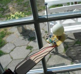
The Solar Tracker project uses this characteristic to
track the sun's movement across the sky.
BI-COLOUR, TRI-COLOUR ,
FLASHING LEDS and 7-colour LEDs
LEDs can also be obtained in a
range of novelty effects as well as a red and green LED inside a clear
or opaque lens. You can also get red, blue, white, green or any
combination inside a LED with 2 leads.
Simply connect these LEDs to a 6v supply and 330R series dropper
resistor to see the effects they produce.
Some LEDs have 3 leads and the third lead needs to be pulsed to change
the pattern.
Some LEDs can be reversed to produce a different colour. These LEDs
contain red and green and by reversing the voltage, one or the other
colour will illuminate.
When the voltage is reversed rapidly, the LED produces orange.
Sometimes it is not convenient to reverse the voltage to produce orange.
In this case three leaded LEDs are available to produce red, green and
orange.
FLASHING LEDs
Flashing LEDs contain a chip and inbuilt current-limiting resistor. They
operate from 3.5v to 12v. The flash-rate will alter slightly on
different supply voltage. You can get 3mm and 5mm versions as well as
high-bright types and surface-mount.
At 3v, the LED will (may) operate at very low brightness. As you
increase the voltage 5v to 6v, the brightness increases to a very good
illumination. Voltages over 7v are not recommended without adding an
external resistor to limit the current to 20mA. Some flashing lEDs may
work to 12v without any additional resistor but the current will be 30mA
to 40mA and the life of the LED could be very short. There is no way of
knowing the voltage range, but if you keep the current to a maximum of
25mA, the life of the LED will be more than 10 years !!
NOVELTY LEDs
Novelty LEDs can have 2 or three leads. They
contain a microcontroller
chip, inbuilt current-limiting resistor and two or three colours.
The two leaded LEDs cycle through a range of colours, including flashing
and fading.
The three leaded LEDs have up to 16 different patterns and the control
lead must be taken from 0v to rail volts to activate the next pattern.
LEDs LEDs LEDs
There are hundreds of circuits that
use a LED or drive a LED or flash a LED and nearly all the circuits in
this eBook are different.
Some flash a LED on a 1.5v supply, some use very little current, some
flash the LED very brightly and others use a flashing LED to create the
flash-rate.
You will learn something from every circuit. Some are
interesting and some are amazing. Some consist of components called a
"building Block" and they can be added to other circuits to create a larger,
more complex,
circuit.
This is what this eBook is all about.
It teaches you how to build and design circuits that are fun to see
working, yet practical.
You will learn a lot . . . . even from these simple circuits.
Colin Mitchell
TALKING ELECTRONICS.
talking@tpg.com.au
SI NOTATION
All the schematics in this eBook have components that are
labelled using the System International (SI) notation system. The SI
system is an easy way to show values without the need for a decimal
point. Sometimes the decimal point is difficult to see and the SI system
overcomes this problem and offers a clear advantage.
Resistor values are in ohms (R), and the multipliers are: k for kilo, M
for Mega. Capacitance is measured in farads (F) and the sub-multiples
are u for micro, n for nano, and p for pico. Inductors are
measured in Henrys (H) and the sub-multiples are mH for milliHenry and
uH for microHenry.
A 10 ohm resistor would be written as 10R and a 0.001u capacitor as 1n.
Some countries use the letter "E" to represent Ohm, such as 100E = 100
ohms = 100R.
The markings on components are written slightly differently to the way
they are shown on a circuit diagram (such as 100p on a circuit and 101
on the capacitor or 10 on a capacitor and 10p on a diagram) and you will have to look on the internet under
Basic Electronics to learn about these differences.
We have not provided lengthy explanations of how any of the
circuits work. This has already been covered in TALKING ELECTRONICS
Basic Electronics Course, and can be obtained on a
CD for $10.00
(posted
to anywhere in the world)
For photos of nearly every electronic component, see this website:
https://www.egr.msu.edu/eceshop/Parts_Inventory/totalinventory.php
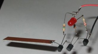
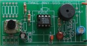
How good is your power of observation?
Can you find the LED:
|

 The
output voltage depends on how quickly the magnet passes from one end of
the slide to the other. That's why a rapid shaking produces a higher
voltage. You must get the end of the magnet to fully pass though the
coil so the voltage will be a maximum. That’s why the slide extends past
the coils at the top and bottom of the diagram.
The
output voltage depends on how quickly the magnet passes from one end of
the slide to the other. That's why a rapid shaking produces a higher
voltage. You must get the end of the magnet to fully pass though the
coil so the voltage will be a maximum. That’s why the slide extends past
the coils at the top and bottom of the diagram.
 LEDs
on 240v
LEDs
on 240v The
current-capability of a capacitor needs more explanation. In the
diagram on the left we see a capacitor feeding a full-wave power supply.
This is exactly the same as the LEDs on 240v circuit above.
Imagine the LOAD resistor is removed. Two of the diodes will face down
and two will face up. This is exactly the same as the LEDs facing up and
facing down in the circuit above. The only difference is the mid-point
is joined. Since the voltage on the mid-point of one string is the same
as the voltage at the mid-point of the other string, the link can be
removed and the circuit will operate the same.
The
current-capability of a capacitor needs more explanation. In the
diagram on the left we see a capacitor feeding a full-wave power supply.
This is exactly the same as the LEDs on 240v circuit above.
Imagine the LOAD resistor is removed. Two of the diodes will face down
and two will face up. This is exactly the same as the LEDs facing up and
facing down in the circuit above. The only difference is the mid-point
is joined. Since the voltage on the mid-point of one string is the same
as the voltage at the mid-point of the other string, the link can be
removed and the circuit will operate the same. 


 If
3rd band
is gold,
Divide by 10
If
3rd band
is gold,
Divide by 10