|
27MHz Receiver |
|
|
This project is the receiver section of a 2-Channel 27MHz link. It has 4 outputs and these can be individually controlled by pressing button A for a short or long period of time and the same with button B.
But basically is is a 2-Channel Receiver.
See the 27MHz 2-Channel transmitter HERE.
Detecting the 2 Channels
The antenna picks up all the surrounding frequencies but an exact frequency of 27MHz makes the front-end produce a higher waveform that has a frequency of 27MHz.
This frequency is called the carrier frequency and the transmitter increases and decreases the amplitude at the rate of 600 times per second for one of the "tones" and 1,200 times per second for the other tone.
A small-amplitude 27MHz waveform is produced by the first transistor and it increases in amplitude when it detects a 27MHz signal from the surroundings and this amplitude increases and decreases at a rate of 600 times per second.
Only the 600 cycles per second signal is passed to the amplifying stages and any noise above this frequency is removed by the feedback components (capacitors) on two of the stages. The only signal that appears at the output of the fourth transistor is a 600 or 1,200 cycle signal.
Detecting one signal from the other is not easy. The two frequencies are very close and producing two circuits to separate them requires many components.
The simplest solution is to add a chip to count the number of cycles in a short period of time and produce two separate outputs.
We have done this with a PIC chip and provided two other features to detect a long tone from switch A and a long tone from switch B.
This produces 4 separate outputs.
THE CIRCUIT
The changes in red have been added to the
Printed Circuit Board as surface-mount components THE "FRONT-END"
The secret to getting a long-range 27MHz link is a powerful transmitter and a sensitive "front-end" on the receiver.
A 27MHz transmitter of only a few milliwatts (10 to 30 mW) will reach 100 metres providing the receiver has a very sensitive FRONT END.
The Front End is the first stage of a receiver.
In our case it is a very weak 27MHz oscillator and thus it is actually a 27MHz transmitter (or more accurately - a 27MHz radiator) as it fills the surroundings with a 27MHz signal.
When another 27MHz signal enters this field it upsets the transmission of the receiver and increases the amplitude of the oscillator. This has the effect of producing a cleaner signal and the background noise or "hash" is reduced.
This is a very clever way of making the front-end very sensitive as it takes a lot of energy to "excite" an oscillator that is sitting in a dormant condition. It is also very difficult to get an oscillator to sit in a condition that is just before the point of oscillation. So we cause it to oscillate at a very low level and an incoming signal will increase the amplitude.
The fact that the transistor in the front end is oscillating can also be referred to as a REGENERATION circuit as the output of the transistor - at the collector - is fed back into the circuit via the 39p between the collector and emitter.
The signal delivered by the 39p is prevented from being lost to the 0v rail by the 50 turn inductor. This is called "emitter injection" as the transistor is configured as a common base amplifier in which the base is held firm by the 22n and the signal fed into it via the emitter.
The operation of the circuit is kept at a low amplitude and when the antenna picks up a signal of exactly the same frequency, the amplitude increases. This is called SUPER REGENERATION or increase of the regeneration.
It is a very simple way of getting an enormous result from very few components. Normally you would require 2 or more stages of amplification to produce the same result.
The only problem with a SUPER REGENERATIVE circuit is the background noise it produces. But since this project is designed only to activate a load, this background "hash" is not a problem. Nearly all the background noise is removed by the feedback capacitors on each stage.
A capacitor placed between the collector and base of a transistor has an enormous effect on reducing the high frequencies.
That's why a small capacitor such as 2n2 can be used. The gain of the transistor (about 70) multiplies the effective resistance (impedance) of the capacitor by about 70 and the background noise is removed because it mostly consists of high frequencies.
But there is still a lot of skill to get the front-end to oscillate very lightly, while being sensitive to signals coming from the antenna.
A high-value resistor in the collector only allows a small current to flow and if the supply voltage is high, this produces a circuit that will oscillate with a small waveform and can be easily "upset" or "modified" by an injection at the highest point of oscillation. If this injection is timed accurately, it will increase the amplitude of oscillation and the high voltage supply will allow this to occur.
The output of the front end is taken from the collector of the transistor - but not directly from the collector as this would load the circuit and stop it oscillating. The top of the oscillator coil will have a small percentage of the waveform (that is generated on the collector) and we can amplify it via three stages of amplification. The important thing is we can only pick off a very small percentage of the energy from the oscillator so the front end keeps oscillating.
The signal appearing at the "pick-off" point consists of:
1. - 27MHz frequency called the "carrier frequency,"
2. - a lot of noise and "hash" produced by the circuit and also from the antenna picking up background noise from the surroundings and
3. - a tone from the transmitter.
The tone is about 1kHz and its frequency is considerably different to a 27MHz frequency so a simple PASS FILTER can be used to remove the 27MHz and only allow the tone and noise to pass to the next stage.
The component that does this is the 22n across the 4k7 in the supply-line.
This capacitor effectively passes (shunts - removes) the 27MHz to the positive rail where it is passed to the 0v rail via the 47u electrolytic. Thus it NEVER gets passed to the amplifying stages.
We only want to VERY LIGHTLY load the front so we don't stop the circuit oscillating.
We do this by using a resistor and capacitor in series.
If we just use a capacitor, the "resistance" of the capacitor will be quite small at some of the frequencies of the "hash" and it will load the circuit and reduce the amplitude when a signal is being received. Even though the top of the oscillator coil is connected to "earth" via a 22n, another 22n "pick-off" will reduce the signal slightly as it will have a "resistance of about 5k to 7k because it is only passing audio frequencies. To increase this resistance we add a resistor in series with the "pick-off" capacitor.
The combination of the resistor and capacitor in series reduces the LOADING effect.
We now have a very small signal that can be amplified by the following 3 stages.
The second transistor amplifies this signal and removes a lot of high frequencies (hash) via the 2n2 feedback capacitor.
The third transistor does exactly the same and we finish up with a signal that is almost equal to rail voltage from the fourth transistor.
We need a very high amplitude signal for the PIC12F629 microcontroller. That's why there are three stages of amplification.
The microcontroller counts the number of cycles in 100mS and determines if the tone is from button A or B. We could have a count in 10mS because the two frequencies differ by 100%, and this is something you can do when you start writing your own programs for a microcontroller.
It also counts in increments of 100mS and if the signal is present for 5 x 100mS, it is counted as a long pulse.
THE INDUCTOR
The inductor on the emitter of the transistors plays a very interesting part in the operation of the circuit.
The transistor is configured as a COMMON BASE amplifier and the base is held rigid by the action of the 22n on the base.
Amazingly, this capacitor has a "resistance" of less than 0.5 ohm at 27MHz and so you can see the base is held firmly.
The signal on the collector is passed to the emitter via a 39p and its "resistance" is about 150 ohms at this frequency. So you can see the signal on the collector has a fairly low resistance path to the emitter and this capacitor will have an effect on the amplitude of the signal on the collector.
However this capacitor does two things. It turns the transistor ON more and it turns the transistor OFF.
Let's see how the capacitive reactance (the resistance at 27MHz) has an effect on the amplitude of the signal.
We know the base is held rigid but the emitter is also held rigid when the signal is not increasing or decreasing.
It is held rigid because the inductor has a very small resistance (3 ohms) and the 2n2 capacitor between the inductor and 0v needs time to charge and discharge and so it also holds the voltage on the emitter at a rigid potential.
But let's look at the effect of the base-emitter junction. When the 39p tries to LOWER the voltage on the emitter, it has the effect of turning the transistor ON more and the base-emitter junction acts like a very low resistance. This means that when the voltage on the collector is reducing, the 39p acts like a very low resistance to lower the voltage on the emitter and the voltage on the emitter drops by only a few millivolts.
During this time what is the inductor doing?
To answer this we will explain how a capacitor and inductor works.
A capacitor is like smashing up against your opponent in a football match. He wont let you pass him and he grabs on to you so you cannot back away.
That's what the 2n2 capacitor does when it sees an increasing or decreasing voltage. It RESISTS the increase or decrease and the top of the capacitor is just like connecting to the 0v rail.
But an inductor is different.
It's like your team mate lifting you up to reach the ball when you charge at him.
If you supply an increasing voltage to one end of an inductor (the other end is at 0v), the inductor will produce a voltage of the same amplitude and it will seem the INDUCTOR HAS DISAPPEARED !
This is the most important concept you will learn about inductors. Once you realise the inductor disappears, you can see how it has no effect on reducing the signal.
That's exactly what happens in this circuit.
The inductor allows the signal through the 39p to have an effect on controlling the voltage on the emitter without absorbing any of the energy.
The inductor does not have any positive effect on the circuit, is just does not have any loading effect.
In other words, the voltage developed across the inductor does not add to the waveform. But the coil on the collector DOES have an effect on the amplitude of the waveform.
THE TOP INDUCTOR
The top coil (inductor) is actually part of a building block (circuit) called a TANK CIRCUIT.
It just needed a capacitor to be called a tank circuit. The capacitor can be in series or parallel, but it is normally a parallel circuit. This name came from the early days of radio where they realised the coil and capacitor stored energy during the first part of the cycle and released it during the second half. It stored energy like a water tank.
This coil works in a completely different way because it has a capacitor connected across it.
The bottom inductor acts like a component that "disappears" when a signal is delivered to its input lead.
The top coil acts like a much smaller opponent that you can reason-with and create a double "high-five." The transistor delivers energy to the coil and it produces a voltage on its lower lead so that the voltage across the coil is equal to about rail voltage.
The transistor now turns off and the magnetic flux created by the coil collapses and produces a voltage in the opposite direction and this voltage charges the capacitor across the coil.
This reverse voltage can be equal to about rail voltage.
This means the amplitude of the positive voltage and the amplitude of the negative voltage can be as high as twice rail voltage and this signal is passed to the antenna. In our case this amplitude is much smaller, but for a transmitter, the amplitude can be 2 x rail voltage.
THE OSCILLATOR
The first transistor is a 27MHz oscillator.
How does it oscillate?
It oscillates because a signal from the output is fed back to the input.
The feedback signal must be POSITIVE FEEDBACK. Negative feedback will not start an oscillator and any negative feedback fed to an operating oscillator will reduce the output and may even kill it.
So we need POSITIVE FEEDBACK. But this is not the complete answer. The feedback signal must deliver slightly more energy than the transistor requires, at each part of the wave. As the transistor turns ON more and more, it requires more energy from the feedback signal to do this. That's why the value of the 39p feedback capacitor is larger than necessary.
Suppose we use a 10p capacitor, the transistor will turn on and feed some of the energy from the collector to the emitter. But as it turns ON more, the base-emitter junction requires additional energy and the 10p cannot provide this. The result is the transistor does not turn ON fully and it stops oscillating. Alternatively, it may oscillate but at a lower amplitude.
The feedback capacitor will turn the transistor ON faster than we require.
We want a 27MHz oscillation.
To get the transistor to turn ON and OFF at the required frequency, we have two components on the collector.
These two components are a coil an capacitor.
When they are connected in parallel, the coil picks up signals (called electromagnetic radiation) from the surroundings and a very small voltage is produced by the turns.
This voltage is passed to the capacitor and it charges.
When it is fully charged, it sends its energy to the coil and this takes a certain period of time because a capacitor cannot charge and discharge instantly. This energy-flow back and forth produces a microscopic amplitude and if a surrounding signal has a frequency that exactly matches the natural frequency of the two components, it will increase the amplitude of the signal and continue this oscillatory effect.
The point to understand is this: The coil and capacitor has a natural frequency at which they operate and if we connect them to a transistor, they will output a waveform that is picked up by the feedback capacitor to turn the transistor ON and OFF at the same frequency.
The coil and capacitor form a circuit called a TUNED CIRCUIT and they determine the frequency at which the circuit operates.
The transistor is simply tuned ON and OFF at exactly the time.
There is just one more interesting part to the circuit.
The top of the coil is fixed to the supply rail via the 22n and when the transistor turns ON, the lower end of the coil becomes slightly negative (slightly less than the voltage on the supply rail).
The transistor keeps turning ON until it is fully turned ON. At this point the feedback capacitor stops providing energy to the emitter and the transistor turns OFF a small amount. This reduces the current through the coil and the magnetic flux changes from expanding flux to collapsing flux.
This has the effect of producing a reverse voltage from the coil and now the end connected to the collector has a voltage HIGHER than rail voltage. This voltage raises the voltage on the emitter and has the effect of turning the transistor OFF.
In other words, the transistor is effectively removed from the circuit and the coil/capacitor combination perform their energy transfer as mentioned above.
The end result is a voltage on the antenna that can be twice rail voltage. In our case the amplitude is kept very low but for a transmitter, this voltage can reach twice rail voltage.
THE AMPLIFYING STAGES
The 3 amplifying stages are called self-biasing common-emitter stages.
The base bias resistor is chosen so the voltage on the collector is about half-rail voltage. This allows both the positive and negative excursions of the waveform to be amplified.
We are not concerned with the quality of the signal (the shape of the wave - the waveform - as we only need to produce a maximum amplitude to feed the microcontroller so it can count the number of pulses - waves - per second.
The value for the components for each stage are chosen by selecting the collector load resistor so the average current will be about 0.5mA. We then select base-bias resistors so the collector voltage sits at about 2.5v.
We then input the signal from the front-end and try capacitors for the negative feedback.
Why waste time working out the values mathematically when it only takes 30 seconds to physically fit a component?
After you generate a mathematical answer, you will want to try different values to see the effect and so it's best to just experiment and see the results on a CRO.
You don't know the gain of the transistor so it's pointless using a mathematical equation to get a result.
The feedback capacitor has an enormous effect on removing waveforms such as "hash" that are higher in frequency than the tone signal, but it also reduces the amplification of each stage. So you have to chose between reducing hash and reducing overall gain of the stage.
Each transistor is called a STAGE.
A stage is a self-contained circuit with a capacitor at the input and and output.
This makes the voltages on the stage entirely generated by the components within the stage because the capacitor on the input and output prevent DC voltages on adjacent stages having any effect.
This makes diagnosis and testing very easy.
If a stage is not working, the first thing you do is check the voltage on the collector of the transistor.
If it is too low or too high, the component may be the wrong value or the transistor may have a very high gain or very low gain. The feedback capacitor may be leaky or damaged or the tracks on the PC board may have a splash of solder.
Audio circuits are very difficult to diagnose and our BENCH AMPLIFIER project can be used to listen to the tone entering and leaving the stage.
You can also use a CRO to view the waveform.
If you want to be really technical you can say the 3 transistors form a "Frequency Selective Strip" - the frequencies being selected are LOW FREQUENCIES.
CONSTRUCTION
A kit of components is available from Talking Electronics.
All the components are included in the kit and everything is identified on the board.
27MHz Receiver PCB layout
The only way you are going to lean about
all the points we have covered in the description above is to build the
circuit and have a problem with its operation.
It's only when you have a problem with a circuit that you start to get
an education.
It's when you have to sit down and work out how solve a problem,
that you begin to learn how something works.
This is an ideal project to learn how transmitters work.
There are so many things you can adjust to get the best range.
And that's why we have produced the 27MHz Field Strength Meter
project. It will help you get the best performance from the transmitter
so you can tune the transistor and receiver to each other to get the
best range.
SETTING UP
When adjusting the air trimmers, you need a non-metal screw-driver such
as a plastic knitting needle to prevent your hand altering the
frequency.
Place the transmitter and receiver a few metres apart on a non-metallic
bench and make sure both antennas are vertical. This makes them both
"in-line" for the best range.
Now turn the air trimmer on the transmitter and you will get a position
where the receiver detects the signal.
This is where the frequency of the transmitter and receiver are
absolutely identical.
27MHz and 49MHz transmitters do not have a very good range and require
considerable power. That's why 100MHz, 303MHz and GHz transmitters are
widely used. But these high frequency transmitters are more difficult to
build and this 27MHz link is designed to get you into understanding the
concepts of transmission - it's the place to start.
27MHz
Receiver-2Ch |
|
1 - 220R resistor 6 - 470R resistors 1 - 1k resistor 1 - 1k5 resistor 3 - 4k7 resistors 1 - 10k resistor 1 - 220k resistor 2 - 470k resistors 1 - 1M resistor 1 - 1M with 1metre 0.095mm wire for inductor 1 - 5-30p air trimmer 2 - 39p ceramics 3 - 2n2 ceramics 5 - 22n ceramics 1 - 100n monoblock 2 - 100n surface mount 1 - 47u electrolytic 1 - 1N4148 diode 4 - BC338 transistors 4 - BC547 transistors 1 - 20 turn coil 3mm dia 0.5mm wire 1 - PIC12F629 micro with 2ChRx 1 - 8 pin IC socket 1 - 78L05ACM 5v regulator IC 1 - 9v battery snap 1 - 10cm 0.5mm wire for antenna 20cm very fine solder 1 - 27MHz Rx 2Ch PCB |
MORE TEST EQUIPMENT
Talking Electronics has a number of pieces of TEST EQUIPMENT to help in the design and testing of projects.
Of course you can use a multimeter for most of the testing but some of the "tricky" faults need a special piece of equipment.
You may only need a LOGIC PROBE once a month, but the project you are designing will come to a stand-still if you can't locate a problem.
We designed all these projects because we needed them ourselves.
Add one of them to each order you place with Talking Electronics and eventually you will have the whole range.
|
27MHz Field Strength Meter Tests 27MHz transmitters $6.50 plus $4.00 post Buy: 27MHz FSM kit |
 |
|
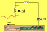
LED TESTER Tests LEDs. $1.50 plus $4.00 post (buy a number of kits and pay only one postage) |
 |
|
CONTINUITY TESTER Only responds to resistance less than 50 ohms. Ideal for digital projects as it tests connections very quickly. $12.50 plus $6.50 post (buy a number of kits and pay only one postage) |
 |
|
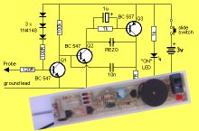
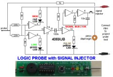
LOGIC PROBE with PULSER
- slimline Detects HIGH and LOW signals on both TTL and CMOS circuits. The piezo allows you to hear low frequency signals and the signal injector (Pulser) will over-ride clock signals to make a circuit operate at a reduced frequency. $8.00 plus $6.50 post |
 |
|
SUPER PROBE 20 different functions. See article for the complete list of functions. $18.00 plus $6.50 post |
 |
|
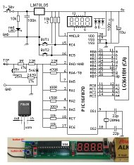
COMBO-2
TRANSISTOR TESTER Tests transistors and shows the gain of the transistor. Also has Signal Injector probe. $21.50 plus $6.50 post |
 |
|
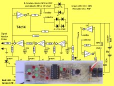
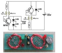
Simple
Transistor and LED Tester - 3 Tests PNP and NPN transistors and LEDs. Also teaches the amazing property of an air-cored coil in producing a high fly-back voltage. $4.00 plus $3.00 postage. (buy a number of kits and pay only one postage) |
 |
|
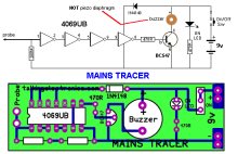
MAINS TRACER Detects 240v AC mains hidden in walls etc. Will also pick up RF signals from a keyboard to show you where Electromagnetic Radiation is coming from and giving you a headache. $10.00 plus $4.50 post |
 |
|
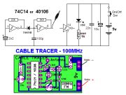
CABLE TRACER
- 100MHz Traces cables when the power is OFF. Uses an FM radio to pickup beeps. $10.00 plus $4.50 postage.
(buy a number of kits and pay |
 |
|
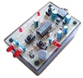
OP-AMP TRAINER and TESTER Teaches how an op-amp works by using pots to control the voltages on the two inputs. $24.50 plus $6.50 post (comes with instructions) |
 |
|
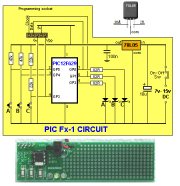
PIC Fx-1 MICRO (8 pin) PROGRAM DEVELOPER and TESTER Learn to program PIC chips. Comes with a pre-programmed PIC12F629 chip with 3 routines. $12.00 plus $6.50 post |
 |
|
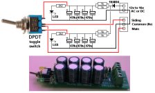
Model Railway
POINT MOTOR CONTROLLER and TESTER
CDU-Inline The cheapest CDU project you can get. $8.50 plus $6.50 post |
 |