SPOT
Page 1
Page 2
Page 3
Page 4
Page 5
Page 6
Page 7
Page 8
Page 9
These pages of SPOT THE MISTAKE are the most important pages you will ever read.
Here's another disastrous circuit from
See our section on Spy Bugs and FM bugs in the left index on the front of
Talking Electronics website to see how a simple FM Bug can be built. All our
bugs work perfectly and over 100,000 kits have been sold.
LOUD PHONE RING
Here we have a circuit from Everyday Practical Electronics February 2014
that has be reprinted from Silicon Chip February 2013.
The whole idea of producing a project is to show the latest and best way to
design a circuit. The skill is to keep it simple with costs as low
as possible. The Whistle Key Finder only needs one transistor
amplifier stage and a buffer output to drive a loud piezo siren with a built-in
oscillator. The piezo diaphragm is connected directly to the base of the single
transistor input stage. The micro does all the work.
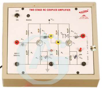
Here's another Indian Professor and his set of Lecture Notes.
Here's another stupid set of diagrams:
Where did he get this circuit from ??
Professor Gupta has simply "copied and pasted" to get this circuit. There are
two R1 R2 etc. In general, the second stage has different values because the
current capability of the stage is greater and the components will reflect this.
The circuit is a BAD example for students.
It is absurd to provide values to many decimal places as no instrument is
capable of measuring to this accuracy. It just shows the incompetence of
Professor Gupta.
Here's a complete lack of understanding of the basic laws of computations:
How can the current flow in both directions at the same time ???
THE MISTAKES!
Page 20
Page 10
Page 11
Page 12
Page 13
Page 14
Page 15
Page 16
Page 17
Page 18
Page 19
Page 21
Page 22
![]()
Although the web is wonderful, it is filled with too many sites that offer no
information other than links to other sites and masses of dead-ends.
In the process you are confronted with irrelevant advertisements.
On top of this are the sites that stat with a lot of fan-fare and rapidly fizzle
into nothingness.
I recently tried to find sites offering a Basic Electronics course, as I thought
this had been fully covered.
I was asked to review a book:
COMPLETE ELECTRONICS SELF-TEACHING GUIDE with Projects by Earl Boysen and Harry Kybett.
Not only did I find the book completely lacking in some of the most basic
circuits and topics, there were innumerable mistakes and complexities that
should have been removed from a "basics book."
After an enormous amount of searching on the web, I came to the conclusion that
this area had not been covered to a level that a teacher could send a student to
a single website and learn about basic electronics.
That's why I wrote the eBook "Basic Electronics 1A."
The quality, complexity and completeness of the internet is so valuable and
fulfilling that it will very soon become the teaching facility of the future.
It just requires a little more sorting and co-ordination to get all the
relevant material into sections so the reader can progress without having to
sift through redundancy, while getting all the important facts.
It may have been suitable in the last Century to have schools and Universities
with hourly lessons and lectures but with the advent of the internet; the time,
energy and expense travelling to and from classes can now be saved by using the
internet to deliver the information.
I know Universities are baulking at this proposal because it is showing their
gradual redundancy, but the web will over take conventional centres of learning.
It is already happening. Lots of mediocre and meaningless University degrees are
already available on the internet and some sections of technically-advanced
courses are available.
Practical-work will still need to be done and possibly some of it can be done
with kits through the postal system.
For a $20,000 course, you can get a lot of technical material.
Who would have thought the teaching profession would become redundant????
This is going to be the next big change in education.
Students will acquire their training through the internet and attend blocks of
practical work and final examinations.
"On-line" degrees will have to be accepted.
This is the way of the future.
Who would have thought GOOGLE would make all this successful ????
![]()
How do you think I got my intensive understanding of electronics?
By repairing electronic equipment.
Some circuits work for 5 years then stop working.
The best thing to test the circuit is a damp finger. Push your finger against
all the pads on the bottom of the board. It will detect if a resistor has gone
open or an open capacitor. Then probe around to see if a joint has become
faulty.
You learn much more when repairing a circuit because you have to "see" how it
operates.
And that's what these pages are doing. They show you how to "see" a fault and
how to correct it.
![]()
Before designing a project, you should look on the web and see what has been
done. It is pointless designing a circuit that is more-complex than pervious
designs. The skill is making a simpler circuit or one that works better than
anything presented previously.
Here is a typical disaster from EFY.
It uses a 16 ohm speaker as the microphone. No only is it larger than an
electret microphone but it is less sensitive. Why include a transformer when a
741 op-amp will amplify the slightest waveform??
Two transistors could replace the transformer and op-amp and take up less space
on the board.
The rest of the circuit is very complex and simply specifying an inductor as
50uH is not sufficient. The name of the manufacturer and the current
capability of the inductor is also needed as some inductors will work and others
will be very poor. The size and shape of the 4-turn coil L1 is very poor. The
turns of a coil should be spaced no more than the thickness of the wire for good
inductance whereas this coil has very widely spaced turns.
Overall a disastrous circuit with twice the number of components as our designs
and very poor sensitivity with a speaker as a microphone. ![]()

The past few years of Everyday Practical Electronics has been filled with
reprints from Silicon Chip and no new projects have been delivered.
This might be good for Silicon Chip with re-write revenue coming in, but
is certainly not in the best interests of the hobbyist.
A hobbyist will have already seen these projects (as I have) and it's just a
re-gurgitation.
But the main point of the project is the complexity. The op-amp could be
replaced with a couple of transistors and if you want to really condense the
circuit, it could all be done using an 8-pin microcontroller, as shown in our
project Whistle Key Finder:
![]()
The descriptive English is absolutely TERRIBLE and I can hardly understand what
he is trying to say. It is no wonder Indian students finish their courses
with little understanding of electronics.
Here's a typical example of muddled thinking:
The explanation is WRONG. The current flows in the direction of the arrow on the
symbol of the transistor:
The current flowing through the transistor in the bottom diagram will flow
through the base-emitter junction to turn the transistor ON and the voltage
developed across the base-emitter junction will be set by the current flowing
through the collector-emitter junction. The transistor will not be fully
saturated as the collector-emitter voltage will not be as lows as possible
(0.2v) but about 0.65v.
Show me one project using a PNP transistor with positive voltage on the lower rail. This
is an absurd circuit to use in lecture notes. It has never been used in
practice.
Here's another faulty diagram:
The third diagram has the supply voltages incorrectly drawn. How does a LOAD
RESISTOR have a voltage across it ???
The 100k resistor may have an accuracy of 1% and yet the "Professor" has given
the current an accuracy of 1/100th of one percent. The answer cannot be
any more accurate than the worst-given-data. And, in fact the voltage is
provided as "whole volts" and the data cannot be more accurate than "whole
amps."
Another absurd result:
How can you get 10.498mW when the voltage is only accurate to one-tenth of a
volt ???
Look at this terrible English:
Block DC, allow AC to follow - what does this mean ????
Large C gives less ripples ???? - NO.
A large C reduces the AMPLITUDE of the ripple.
![]()
Should be:
![]()
Although we say Alternating Current for the waveform delivered by the mains, we
are really dealing with the voltage and this is why we say "AC." AC is
another way of saying "Oscillating Voltage" Rectification changes the
characteristics of the VOLTAGE and this is the parameter we are dealing with.
I have no idea what the "Professor" is trying to say:
What are the arrows supposed to represent ??

Should be
Central Processing Unit
The battery symbol has not been reversed in the second
diagram:
Common Collector Characteristics
Should be:
For a transistor with Hfe = 100, the input impedance is 100 x load resistance
Output resistance = LOAD resistance (can be 1 ohm to many kilo ohms)
Current gain 20 to more than 300 (depending on transistor type.
Voltage Gain = Less THAN unity.
If the input is an AC waveform, it does not have
"+" and "-" identification:
How can 0v be present at the join of the two 1k
resistors ???
The discharge transistor should be NPN:
What is impendence
?![]()
What does this mean:

This is only a few of the faults.
I emailed Professor Rajesh Gupta at Indian Institute of Technology Bombay and
got this incredible reply:
Keep your comments with yourself we do not need it .

Professor
Rajesh Gupta
rajeshgupta@iitb.ac.in
Department of
Energy Science and Engineering
Indian Institute of Technology Bombay,
![]()
Here's a table from a set of lecture notes:
How can the input impedance of a Common Collector (Emitter-Follower) stage be
580k when the generally accepted input is the gain of the transistor (20 to 200)
multiplied by the load resistance (in the emitter).
This type of stage is ideal for driving a
low resistance LOAD such as 5 ohms to 200 ohms.
The transistor makes it 20 to 200 times "easier" to drive the load.
None of these "practical" points are mentioned in the lecture notes because they
are written by someone who has NEVER actually constructed any of the circuits
and merely cobbled together bland, uninteresting, poorly documented notes with a
heavy emphasis on using technical terms and formulae that will take hours to
process.
Instead of trying to work out any of the voltages and current in a particular
design, simply build the circuit and you will find your theoretical values are
WAY OFF. That's because a transistor is not linear and since the gain can be 100
to 250 in a batch of devices, you have no way of working out the correct values.
Secondly, no boss is going to allow you to sit down and compute the results at
HIS expense and then find the results are 50% inaccurate.
Simply build the circuit on a matrix board and place the components in the same
places as for the final design and you are doing three things AT ONCE.
You are building the circuit, making sure it works, getting a layout and size,
determining the parts required and getting it ready for PCB designing as well as
determining the current requirements.
That's why the dumbest workers are not always the most stupid.
I had one worker who could draw the entire circuit for a 10 watt audio amplifier
at a moment's notice. That's what I call dedication.
If you look at some of the lecture notes and see transistors drawn up-side-down
and negative rails at the top, you wonder why students come out of a 3-year
course with little REAL understanding.
![]()
Here is a fault in a set of Lecture Notes: The corrections are in
red.
![]()
More faults from Indian Lecture notes:
Three faults:
A zener diode DOES NOT ALLOW current to flow until a specified voltage is
applied.
The applied voltage is NOT called the zener voltage. The applied voltage is
called the APPLIED VOLTAGE and when it reaches the zener breakdown voltage,
current flows through the zener. Normally the applied voltage uses a resistor
between the applied voltage and the zener to restrict the current through the
zener and allow the zener to create the exact zener voltage.
When the zener conducts, current flows from CATHODE to ANODE.
![]()
Zener diodes can be made from 3v to more than 50v.

What does this mean ????
![]()
To Mr Tim Summer: Outputs DON'T draw current.
Outputs either sink or source current.
The 10k resistor will only allow 24mA to flow. The globe needs more than 3
amps.
A terrible example to give a beginner.
What is meant by UNSTABLE?????? I have absolutely no idea what he is
talking about.
![]()
Here's the type of absurdity from an Indian who produces a website and boasts he
gets one million visitors each month:
He has produced a page with dozens of questions but NO ANSWERS.
Here's his reply from a visitor:
Could you please tell me the answers to question asked in interview?
I don't plan to post any answers or reply to this kind of requests. Question are
there for you to get a idea of how the questions would be in an interview.
Deepak Kumar Tala
http://www.asic-world.com/faq.html
What is the point of annoying a beginner by posing questions and not replying
????
![]()
This is the sort of thing that ANNOYS ME. The most important part of the
discussion is to answer the question: How about 11k?
The answer is simple: The transistor is fully turned on with 10uA into the base
and the voltage across the collector-emitter leads will be 0.2v when any current
up to 1mA flows. With 11k load, the current will be slightly less than 1mA and
Vce will be 0.2v When the current is more than 1mA, the transistor stars to turn
off slightly and the collector-emitter voltage increases.
OR GATE
How does this circuit work ???? This is supposed to be an OR-gate for a beginner !!!!! It's not an OR-gate.
The graph is incorrect. The Y-axis is supposed to be DC volts and the peak of 20v AC will be about 30v.
![]()
This is one of the best set of TRUTH TABLES:. It is simple, clear and has the Boolean expression for each gate. NO mistakes on this example:
![]()
UP SIDE DOWN !!
Here we have an Indian demonstration module using PNP transistors and the power
rail is NEGATIVE !!
How can you expect beginners to learn electronics when they are being taught
with circuits that are not in the real world !!!
![]()
 Sometimes
you come upon idiots like DerStrom8 who makes outrageous claims
on Electronics Forums without the slightest clue about anything.
Sometimes
you come upon idiots like DerStrom8 who makes outrageous claims
on Electronics Forums without the slightest clue about anything.Never trust anything you find on Talking Electronics. They're all either stolen designs or very poorly thought out ones that in some cases can be downright dangerous. Personally, I'd recommend looking for a different circuit from another site, one that Colin DIDN'T make.
What a surprise !!!!
He has never come to me and pointed out all the "STOLEN DESIGNS" the "DANGEROUS DESIGNS" or the "POOR DESIGNS."
Another reader said: I built his fluorescent inverter for my van a while back and it worked.
His answer: I'm not saying his circuits don't work, I'm saying they're very poorly designed and in most cases won't last very long (if at all).
It would be wonderful if he came to me and pointed out "all the poor designs"
I have been selling kits for more than 30 years and some readers still have the TEC-1 computer, we designed over 20 years ago. I have sold over 100,000 kits and NO-ONE has said any kit has failed.
You are just making a FOOL OF YOURSELF, stating things that no-one else backs-up and without any examples.
I would have said he was totally-uneducated but he keeps harping on his University Education. I would have thought a University Education would have taught him to back-up every claim with factional material.
Obviously the education has taught him NOTHING.
I would like to know where my "stolen designs" come from?? Someone must be as clever as ME !!
As a point to note: I produced an electronics magazine for 20 years and just after the release of the first issues, one of the other magazines sent representatives to all the advertisers with an offer of half-price advertising for 12 months. When my advertising manager called on the advertisers, they had already spent their advertising budget for the year.
Undaunted, I produced the magazine WITHOUT any advertising.
This annoyed the other magazine so much they produced a HOBBY ELECTRONICS MAGAZINE for 95 cents whereas mine was $1.20.
They flooded every newsagent with their magazine in an attempt to kill mine.
I persisted and eventually they rang me to say: You have won the day." They pulled out with a loss of over $45,000.
But the worst part is this: They read every issue of my magazine and told one advertiser that if they found one paragraph that had been copied from any of their publications, they would sue TALKING ELECTRONICS.
Obviously they never did.
I produced hundreds of circuits and have hundreds that never reached publication.
None of my circuits were even vaguely similar to anything designed by anyone else and I have never been served with a copyright infringement.
I have sold over 750,000 books and never received a letter or comment on a faulty design or poor engineering. For someone to say "STOLEN," "DANGEROUS" or "POOR DESIGN," without any references, just goes to show that an education is worthless.
You don't even get this sort of stupid behaviour from STREET URCHINS.
The problem is the ELECTRONICS FORUM WEBSITE closes down the discussion before anyone can respond.
This has happened on many occasions where the whole discussion has been drivel and when you respond with comments that expose their ignorance, they "moderate" your reply and TURN YOU OFF.
But the good news is, other people are stealing my circuits and putting them on their site, without any reference to Talking Electronics. However everyone knows the layout of my circuits and it gets referenced back to me.
I have never said all the 555 circuits were invented by me. All the simple circuits are generic and have been known for years. I have sorted them out and put in all in a single file for easy reference. That's why I get 7,000 visitors each day, of which about 200 - 300 read the "555 section." Hobbyists keep coming back because everything is neatly arranged and easy to find.
No-one else has provided the extensive content or backed it up with descriptions of how the circuits work.
I only take comments, like those above, seriously if concrete evidence is provided. Otherwise it's just "sour grapes."
It only upsets me to think a person with a "University Degree" would make such a FOOL of himself. It's a bit like doctors (like Dr Shipman who killed 50 old women) damaging the profession by making idiotic statements.
![]()
Here is a typical result from readers of the electronics forums. The
request is for a very simple circuit:
In other words, I want a circuit that will do the following:
I push the trigger, then there is a time delay where the LED is off, then after the delay, the LED is turned on, and remains on. It is aimed as a one time use, its use in my project is only required to turn on automatically once, then I can reset manually for the next time.
A 555 takes 10mA when sitting around doing nothing and is very wasteful. My suggestion is as follows:
However if the original poster wants a 555 circuit, here is the answer:
Here are some of the answers from other readers:
As you can see, some of the circuits are very complex and you would think they
represent GOOD ENGINEERING.
But the skill in designing a circuit is NOT to create a COMPLEX design, but the
simplest design possible.
Anyone can add more and more stages to get a final result, but the skill is to
look at the original requirement and work out the simplest circuit possible.
The first transistor circuit (above) uses the gain of the transistor and the
very small current through the 470k base resistor to deliver about 10mA to the
LED without a current-limiting resistor in the emitter.
If you go back to the first few pages of this eBook, you will see mass produced
circuits with extra components and faulty designs that depleted the battery in
2-4 weeks.
Every time you design a circuit, you need to take into account the simplicity of
the circuit as someone else will see the design and remove a few components and
put it on the market at a lower price.
The happened with the Goddard turntable. It had over 120 components with cranks
and levers and push rods and friction-bearings, just to put the arm on the
record.
Someone came in with a cam-version with 10 components and overtook the market.
I want to mention something that aired on cable vision today.
My father worked for the Sunshine Harvester Company 60 years ago and the owner
had designed a horse-drawn harvester for wheat that stripped the seeds from the
stalks. This resulted in some of the seeds being dropped to the ground and any
stalks that were blown over by the wind before harvesting, were not able to be
harvested.
A young farmer who left school at 14 saw the problem and bought books on
engineering (while living in a country town).
He thought of the idea to cut the stalks and separate the seeds ON THE HARVESTER
and throw the chaff out the back.
He had no education, no tools and no money.
He built a prototype in his shed out of junk lying around and this 3rd prototype
worked very well. He had a contest with his brother and his equipment worked
better and faster.
His patents were bought by the Sunshine Harvester Company and his design was the
best in the world.
Eventually every-one else in the world copied his idea and it's very hard to
realise that he was the inventor of the Self-propelled Combine Harvester.
I am bringing up this point as the new round-bale harvester is so simple
compared to the original rectangular bale that it would amaze you.
Someone saw the complexity in cutting and ramming fodder into a rectangular
shape that he thought of creating a round bale that was not only cheaper to
produce, but 6-10 times larger and could be rolled across the paddock.
This is what I call BRILLIANCE.
These few men have saved the farmers billions of dollars. Absolutely
billions.
Not only do the harvesters pick up wind-blown crops, but they are bigger,
faster, GPS controlled and gather more of the crop than ever before.
You can actually say they turned farming from a disaster to a success.
Farmers only work on a 5% profit-margin and nearly all of them would say the
profit-margin is more like 1%. Nearly all farmers in Australia are bankrupt and
if it were not for the 15% improvement produced by cutting the "ears" instead of
stripping the seeds, wheat farming would have never flourished. It's as
simple as that.
I can remember my father saying the company was changing from wire-tying square
bales to rope tying.
One of the engineers had the job is designing the tying mechanism.
He left work on Friday and worked on the design during the weekend and returned
on Monday with the answer.
That's what I call CLEVER. I know inventors are clever, but to be given a
challenge like this is quite considerable.
This operation had never been done before and tying with wire is completely
different to tying with rope (string).
Even though this website concentrates solely on electronics designs, you have to
have an appreciation for mechanical engineering if you call yourself a true
engineer.
![]()
If a student was told his teacher is USELESS, he could look on the web and teach
himself the correct way to learn electronics.
Look at this RUBBISH from a teacher using a PowerPoint Presentation:
It is supposed to be a VOLTAGE DIVIDER. This is how the circuit is supposed to be drawn:
The pot is now clearly across the rails and provides a percentage of the rail-voltage to the LED. The battery is drawn as a number of cells and there are no "squiggles" in the wiring of the circuit. I can clearly see what is happening with this circuit. This is the way a circuit should be drawn. It should be clear and simple and create an immediate "picture." The other circuit was drawn by a teacher who knows NOTHING about electronics and is just WASTING THE STUDENTS TIME.
Another poor circuit:
You only need 1 resistor. This circuit is giving the wrong example to a student.
Switch 2 is shorting across the battery !!!!
How much more stupid does a teacher have to get ???
I have no idea what this circuit is supposed to do:
The teacher is supposed to be talking to BEGINNERS. He introduces ASYMMETRIC properties of a capacitor, when he can't even spell "Known." And there are MANY different types of capacitor, not just two.
He talks about Capacitors in Parallel:
He really means CAPACITORS ACROSS THE SUPPLY. Capacitors In Parallel
refers to two capacitor in Parallel.
What a disaster !!!
This is an example of
A LITTLE KNOWLEDGE IS A DANGEROUS THING.
![]()
Here's some more untried circuits from Professor D Mohan Kumar:

In the following circuit, the transistor is an emitter-follower and the voltage between base and emitter will be 0.6v. This means the emitter will always be 0.6v above the 0v rail. The LED drops 3.6v, making a total of 4.2v. The voltage across the 10R resistor will be 0.3v and this will allow a maximum current of 30mA. The 1 watt LED will not be very bright!!
The 105 capacitors on the front end are in SERIES, making a total of 470n. This
will produce a current into the circuit of 35mA. The LED will not be very
bright.
But there's another MAJOR FAULT.
Here's the simplest way to look at how a transistor works.
The transistor divides the value of the base resistor by 100 to 200 and
effectively puts the result between the collector-emitter terminals. In the
circuit above the base resistor is 1,000,000 ohms. Divide this by 200 = 5,000
ohms. The LED will get 1.5mA !!!
What a disastrous circuit !!
![]()
Look at this misleading diagram in a set of Lecture Notes:
It should be:
What is 2v with an ARROW ??? We don't use an arrow for voltage as we don't say VOLTAGE has a direction of FLOW. The arrow representing 2v opposes the 10mA current and causes CONFUSION.
THE TRANSISTOR AS TWO DIODES
It is quite STUPID to describe a transistor as TWO DIODES. Firstly, you cannot
connect two diodes to produce a transistor and it is clear the top diode will
never conduct because it is around the wrong way.
Too many discussions go into the physics of how a transistor works with
electrons, holes, depletion-region and more.
All this makes learning very confusing.
It is much better to make a simple statement to say that current into
the base will allow current to flow via the collector-emitter junction. The base
needs a voltage of 0.6v before the transistor turns ON and current into the base
will be increased by a factor of about 100, through the collector-emitter.
![]()
Here's another poor design from Electronics For You March 2014.
No other magazine makes the same mistake over and over and over again. They have
absolutely no idea how to drive a string of LEDs. I have told them more than 10
times and they still create stupid circuits like this:
White LEDs drop 3.2v to 3.6 when they are working. If you construct the circuit
above, the LEDs have only 2.9v across them and the current is 5mA. The battery
delivered 12.8v for this test. With a 12v battery the current was 3mA.
What a useless circuit !!!!
Here's another poorly designed circuit:
LOCKER ALARM
A circuit diagram does not keep all the gates within the chip. That's a wring
diagram.
I have absolutely no idea what the circuit does.
It needs to be re-drawn as a CIRCUIT.
The 100k on pin 6 is not needed. The reed switch must be closed (to produce a
HIGH = 1) and when it opens (=0) the alarm will activate.
The same can be achieved with a BC557 and BC547 configured as a LATCH.
The reed switch is kept open by keeping the magnet away from the switch. When
the locker door is opened, the magnet touches the reed switch and activates the
alarm. Opening the reed switch does not stop the alarm. The power must be turned
off to reset the alarm.
CABLE TESTER
Only 1 470R resistor is needed as only 1 LED is
illuminated at a time.
The 555 can be replaced with a flashing LED to make the circuit very simple.
![]()
Here we have a circuit drawn on the website:
Schematics.com
Anyone can draw and post a circuit that may or may-not work.
This circuit DOES NOT WORK.
Firstly you have to re-draw the circuit:
The circuit re-drawn so you can work out what is
happening
The transistor is a common-base configuration, but the problem is the 250k on
the collector. This value is TOO HIGH. The transistor is tuned on via the 250k
on the base and suppose the transistor has a gain of 250, it will divide the
250k by 250 to become a 1k resistor.
A 1k resistor in series with 250k puts very little voltage across the transistor
and the collector will be about 9v. The 0.5u capacitor will be fully charged.
When the transistor turns OFF, the capacitor is discharged via the 250k and it
will not be discharged vey much.
When the transistor turns ON, the capacitor can only be charged with the very
small amount of energy that was removed by the 250k. This means the transistor
is only acting like a 250k resistor and very little energy will be passed to T1.
That's how you work out what is happening in this type of circuit.
![]()
Electronics For You magazine keeps sending invitations to subscribe each
month and they offer a free gift to the value of the subscription. This means
they make zero profit on a subscription.
Obviously sales are dwindling and their claim of 45.000 subscribers is grossly
exaggerated.
On top of this they have a kit section with somewhat useless kits.
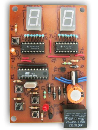
The following kit is a 00-99 counter. Look at the PC board!!!
This is the worst example of a Printed Circuit Board you will find anywhere in
the world. For a magazine to display such rubbish is an indication of their
intelligence.
The kits costs $15.00 plus $40 for postage !!!! It's no wonder they have
NO BUSINESS.
![]()
Another Junk circuit from ELECTRONICS FOR YOU April 2014:
The
circuit tests batteries from 3v to 15v.
Mistakes:
1. The BS170 provides constant current for LED1. RUBBISH !
Build the circuit. The circuit does not work !!!
How does a FET with the gate tied to the source, deliver a constant current ??
What is the constant current ?? How can you increase the constant current ??
THINK . . . nothing makes any sense. Maybe he is trying to say the
LED and BC337 will provide a constant current LOAD, but the circuit has no
current-limiting resistor for the LED.
2. The NE555 does not work below 5v. The circuit WILL NOT WORK on
3v.
What is the reason for multiplying the voltage? The circuit is far too complex.
HOW TO TEST CELLS and BATTERIES:
For AA and AAA cells, use an analogue multimeter set to 500mA range. Test a
single cell and if the needle swings full scale very quickly, the cell is ok.
For alkaline AA and AAA cells, you can use a digital meter set to 10A range. A
good cell will read 2.8A
For a 12v jell cell, use a 12v car globe (18 watt or greater). The globe will
illuminate very bright if the battery is fully charged.
These are GUARANTEED, RELIABLE ways to test a cell or battery. After making lots
of tests with lots of batteries, you will know what to expect.
![]()
Another untested circuit from ELECTRONICS FOR YOU April 2014:
Two 80 watt solar panels are connected in parallel to charge two
80 A-Hr batteries.
This is a HIGH CURRENT design and the tracks on the PC board are as narrow as a
hair ! The charging current will be at least 5 amps and maybe 10 amps and
the power diodes have no heatsinks. One of them could dissipate up to 8 watts
and without a heatsink it will fall off the board. Look at the lands around the
leads of the diodes !! The leads get very hot and will need a very large
land to prevent the solder melting. A lot of the heat from the junction flows
down the leads and they represent a very large percentage of the
extraction-process. The engineer who "flopped" this board
together has absolutely no idea of POWER ELECTRONICS. The diodes are in the
middle of the board. They have no heatsink. They are close together with no
allowance for heat dissipation. What a disaster ! Obviously the circuit has never
been tested.
I have had a 1-amp diode fall of the board because the pad was too small. I have
also had a resistor heat-up enormously because the pad and track was smaller
than for an adjoining resistor. The pad and track provides an ENORMOUS effect on
dissipating the heat from a component and the 5-amp diodes (5-10amp current-flow) need a very
large pad and track to prevent them falling off the board. The leads of a diode
get VERY hot when current is flowing, even though the body of the diode may have
a heatsink.
As soon as you have a circuit carrying more than 1-amp, you need to learn about
POWER ELECTRONICS. The heat generated by a current increases ENORMOUSLY because
it is determined by the formula P=I2R.
For instance, the losses may be 1 watt when 1-amp is flowing but they will be
4 watts when 2-amp flows !!
The losses from a diode increase considerably when the current increases because
the voltage-drop across the junction increases. For some diodes this
voltage-drop increases from 0.7v to more than 1.1v. For the MBR1635, the
increase is only small (from 0.55v to 0.65v). But at 12 amps, the wattage
dissipation can be nearly 8 watts.
None of this has been taken into account when designing the board or allowing
for heatsinks.
When you are preparing an article for 40,000 readers, it has to be presented by
EXPERTS and not contain a myriad of mistakes.
I have had no reply from the technical personnel at Electronics For you.

The trackwork around the power diodes will
never carry 10 amps !!!!!
The track should be between 100 thou and 200 thou
And the pad should be MUCH larger
As a side issue: Electronics For You claim all the
projects are tested. if this is the case, they would have a PC board and the
project built on the board. Where is the photo??? For the same cost they can get
10 boards made and supply them via Kits N Spares. Where are the boards and
where are the kits?
All the projects I design have PC boards and complete kits.
In addition, all my boards have the name of the project and every component is
labelled. When you have 300 different kits, you don't label a board: 9423F.

The only ID on the board is 9423F
When I first started producing my electronics magazine 30 years
ago, the only other electronics magazine in Australia was ELECTRONICS AUSTRALIA.
They labelled their boards CC021985. There was no component overlay, no
solder mask and only bare copper tracks.
I was the first to introduce tinned tracks, a component overlay identifying all
the components, as well as the name of the project.
Every magazine in the world does this, except EFY !!!
This project is signed: "Tested by EFY" Where are the test results?
Where is the photo of the completed project?
You can fool half the people half the time. But you cannot fool all the people
ALL THE TIME. Sani Theo and Rahul Chopra have not answered any of my questions
including: Why use 5v relays when 12v relays are more common, cheaper and
available in 20 amp contacts - especially in India. And the current-rating for
the relays is not mentioned in the text. You have to work that out FOR
YOURSELF. This is another untried, untested project containing a myriad of
problems. All of which have remained UNANSWERED.
![]()
Here's another useless circuit from
http://www.electroschematics.com
and
D Mohankumar
Here is the RUBBISH from D Mohankumar, describing the operation of the circuit
When there is a short-circuit on the PC board you are testing, the voltage on the output pins will be zero.
This means all the current from the power supply will go through the 1N4007 diode and into the PC board and damage the components. The circuit will not provide protection.
Secondly, the voltage of the power supply will drop to less than 1v and the buzzer will not work.
The circuit is a Total DISASTER. Why doesn't he test his circuit before putting them on the web????
![]()
BATTERY CHARGER
This project contains a number of mistakes.
A 17v AC transformer will produce a peak of 17 x 1.4 = 24v and when this voltage
is delivered to a 12v battery, the current will be enormous.
The 5 amp fuse will blow immediately.
The circuit DOES NOT WORK.
The second problem with this type of circuit is the CUT-OFF.
As soon as the voltage across the battery reaches the cut-off voltage set by the
4k7 pot, the circuit will turn off and remain OFF. It may turn on again when the
battery voltage decreases, but this lower point is unknown.
The purpose of the 470R is to provide sufficient gate current to turn ON the
thyristor. The thyristor needs about 25mA gate current and this will occur when
the rail voltage is about 6v higher than the battery voltage.
This means only about 40% of each cycle will be delivered to the battery,
however the losses in the transformer will be considerable and it will get very
hot.
The circuit has no trickle charge feature and it will be very difficult to set
the upper voltage and make sure the battery is fully charged.
The circuit should have a bypass resistor to allow a trickle charge current of
50mA to 100mA.
![]()
Here's another fault from the circuit above:
The circuit puts a load on the battery under test of 120mA. This current flows
through the BC337 and 3R3 resistor.
The 3R3 drops a constant voltage of nearly 0.4v, for any battery under test, and
all the rest of the voltage is dropped across the transistor. For a 12v battery
under test the wattage dissipated in the transistor will be 11.6 x 0.12 =
1.4 watts !!! The transistor is a 600mW device !!
Another stupid circuit by EFY.
No-one on the technical staff of EFY has the BASIC ELECTRICAL and ELECTRONIC
knowledge to spot these mistakes.
If the magazine was a mathematical magazine and contained lots of mistakes, you
would LAUGH !!
You should NOT be reading the magazine. The information they deliver is FULL OF
MISTAKES.
Fortunately I monitored the magazine over a period of 6 months and found NOT A
SINGLE PERSON built any of the circuits and that's why no-one else has picked up
any of the mistakes.
They are so desperate to sell their magazine that they offer a gift with each
subscription EQUAL to the the value of the subscription.
It's a bit like POPTRONICS in the USA. They offered 12 months for $19.95.
The subscription agency received $6.95 leaving $12.00 for 12 issues. The
cost of printing was 50 cents and the cost of posting 50cents. Leaving NOTHING
for the production of the magazine.
Talking Electronics website gets 7,000 visitor each day. This is more than
any of the electronics magazines (on a monthly basis) and it is FREE . .
without having to look at pages of irrelevant advertising.
All the popular magazines are available for FREE download in the web and after
you skim through it, you wonder why you would ever spend $7.00 on a paper copy.
I cut up 10 years of electronics magazines and only kept the articles. I reduced
the pile to less than 5%.
One day I will scan the pages and put them in a .pdf. Many of the articles are
very informative but most of them can be reduced to a single microcontroller and
that's why they are so out-of-date.
![]()
This "NASTY" circuit has been taken from ELECTRONICS FOR YOU May 2014:
It uses the MAINS to derive 5v for the module to test IR remote
controls. I have already mentioned that you can use a camera pointed at the end
of the remote control to view the IR LED and this will save you building any
circuit.
But this circuit is a DISASTER. It uses the mains to derive a 5v supply. It
would be much easier and safer to use 3 x AAA cells.
This type of supply is BANNED from publication in hobby magazines in all WESTERN
COUNTRIES and it about time INDIA stops promoting this type of supply.
D1 is not needed as the 5v6 zener produces the 5v supply. Use 5v1 and omit the
diode. The zener does not have to be 1 watt. It only needs to be 400mW
What is the purpose of the 3u3 when the power rail already has 470u !!!!
The losses in the 180R resistor will be MORE than 5 watts!!!!
Another badly designed DANGEROUS circuit from EFY.
![]()
Here's another STUPID circuit from ELECTRONICS FOR YOU May 2014:
The circuit is designed for the relay to take less current due
to the constant current arrangement of the two transistors.
But the 47k resistor R1 will not deliver sufficient current to turn ON T1.
The simplest way to determine the effectiveness of a resistor on the base is to
allow a gain of 100 for the transistor. This means the value of the resistor is
47,000/100 = 470 ohms. The transistor becomes a 470 ohm resistor in series with
the coil of the relay (400 ohms) and it will get only HALF-RAIL VOLTAGE !!!!!
This can be worked out another way. 5v from a microcontroller will deliver
5/47,000mA = 0.106mA
If the transistor has a gain of 100, it will deliver 10.6mA to the relay.
The relay needs 30mA to PULL-IN.
Another untried, circuit from EFY.
By using my first method of calculation, I could instantly see the circuit did
not work. That's how you quickly diagnose a circuit.
![]()
Instead of making the circuit above, just get a $10.00 TOUCH-TONE phone and
connect it to a 12v battery via a 47R resistor.
Push the keys and listen to the tone in the earpiece.
If the tones are not loud enough, put a speaker on the positive line or add an
amplifier.
EFY would be much better-off by telling the readers how to make something SIMPLE
and not produce a complex circuit, just to fill the pages of the magazine.
![]()
Why aren't there any mistakes from English, US, Australian or German magazines,
in this list ??
Simply because they don't make STUPID mistakes.
If anyone finds a mistake, please send it to:
Colin Mitchell. It will be
included in these pages.
![]()
How many times have I said "NOT TO DRAW BLOCK DIAGRAMS"
Here's a perfect example.
I could not determine how the circuit works from the following drawing:
I then added the gates:
From the diagram above, I saw the circuit DID NOT WORK.
Here is the correct circuit:
By drawing the circuit using GATES, you can clearly see how one gate prevents the other gate from activating its LED:
![]()
Here's another junk circuit from
Electronics Maker magazine.Parts are incorrectly identified, some components are not identified and it appears that a speaker is connected directly to pin 3 of the 555 IC (not identified on the circuit) while the supply is a miniature 12v lighter battery!!
The 0.22P is identified as 0.22u (220n) in the text but the other values are unknown.
The magazine simply has NO electronics capability what-so-ever and that's why the Indian student cannot rise above the stage of "tinkling around."
![]()
Page 1
Page 2
Page 3
Page 4
Page 5
Page 6
Page 7
Page 8
Page 9
Page 10
Page 11
Page 12
Page 13
Page 14
Page 15
Page 16
Page 17
Page 18
Page 19
Page 21
Page 22