SPOT
THE MISTAKES!
Page 19
Page 1
Page 2
Page 3
Page 4
Page 5
Page 6
Page 7
Page 8
Page 9
Page 10
Page 11
Page 12
Page 13
Page 14
Page 15
Page 16
Page 17
Page 18
Page 19
Page 20
Page 21
Page 22
Page 23
Page 24

Statistics are an amazing thing.
I didn't believe in statistics, but when I added "statistics" to my website I
realised how accurate the data can be.
Traffic to the website has gradually increased to 6,000 new visitors per day and
the download has been 600,000 images per day.
But the amazing thing is: The readership of various pages has been
absolutely static for months. We get 225 visitors each day to "50 - 555
Circuits" and 4,500 downloads of the .pdf each month.
While the figures remain constant, the "fall-off" of the printed word
has been enormous.
Magazines and publications are not letting you know, but the purchase of the
physical magazine is falling rapidly. Readers are downloading the issues from
download-sites rather than taking a subscription and it looks like magazines
will go the same way as newspapers.
Apart from requiring less resources, reading on the web is more convenient and more
"instantaneous."
You can easily print-out anything you need and store the rest without having to
take up shelf-space.
Not only that. You can update an article, add corrections and include readers
comments. It's a much-more personalised approach and you can add colour photos
at no extra cost.
ooo000ooo
There are many websites, eBooks and publications on BASIC ELECTRONICS and I am
not going to compete with the information already provided.
That's why I have concentrated on explaining how a fault can develop in a
circuit and how to avoid designing a faulty circuit.
These comments will help both the newcomer as well as the advanced designer as
mistakes have been found EVERYWHERE.
As you know, I fixed TV's and electronic equipment for 20 years and they were
riddled with faults. That's why we were so busy.
Faulty equipment is becoming rare and most devices are thrown out the first time
they fail.
However it is important to know how to design circuits and diagnose them as you
don't want to get fired due to a whole batch of products being recalled due to a
fault in your design. And secondly you don't want to be shown-up when you
fail to analyse a problem.
Test equipment and simulation software is not always the answer. These aids are
very helpful but you still need to know how to rectify the problem.
It's through all these faulty circuits that you get a background of "what can
happen" and "where."
You never know when a fault we have covered will lead you to solving a problem
of your own.
There is so much knowledge on our website that it will take you months to cover
all the information. That's why we have an index on the front of the site and a
CD containing all the 200MB.
This gives you a few choices.
You can buy the CD for $10.00 and load it into a USB stick so you can take it
anywhere or read each article on the site and go through the whole index.
Some of our comments and ideas have never been covered before in any text book
because most of the writers have never built a circuit in their entire life!
It's a bit like Marco Polo never mentioning chop sticks. Because it is doubtful
he actually never went to China.
WHITE LED DRIVER CIRCUIT - POOR DESIGN
This circuit seems to have all the qualifications to illuminate a
white LED, but it is a very poor design.
In the following two designs, the transistor or transistors are being turned ON
by increasing current into the base of the driving transistor and when this
transistor is not turned on, the current is a minimum.
Base-current is effectively wasted current or "wasted energy" and it is kept to
a minimum.
In the circuit above, the base current is constant and will be very small
through a 10k resistor. The circuit consumes 10mA and the LED will see less than
4mA.
By reducing the 10k base bias resistor to 470R the circuit current increases to
25mA but the LED is still not at full brightness.
Secondly, the base-current is shorted to the 0v rail via the first transistor
and is completely wasted during part of the cycle.
But the main problem with the circuit is the fact that the driver transistor is
not driven into full conduction at any part of the cycle and the circuit has
very little efficiency.
An improved circuit is shown in the following diagram:
2-Transistor Joule Thief Circuit
The circuit turns ON via the 220k resistor and the voltage on the collector of
the NPN transistor drops to nearly 0v. This action causes current to flow
through the inductor and at the same time the 1n capacitor is brought towards
the 0v rail and this turns ON the first transistor slightly harder. This action
continues until the driver transistor cannot be turned on any more.
The 1n charges a little more and the current through the base lead reduces
slightly. This action turns OFF the first transistor slightly and the driver
transistor is turned OFF a slight amount.
The voltage on the 1n rises and very soon both transistors are fully turned OFF.
The magnetic flux in the core of the 1mH inductor collapses and produces a
voltage in the opposite direction.
This voltage is added to the 1.5v rail voltage and the final voltage is high
enough to illuminate the white LED.
This keeps both transistors OFF and when all the magnetic flux has been
converted to energy to illuminate the LED, the voltage on the collector drops.
This lowers the top plate of the capacitor and since the capacitor is slightly
charged, the bottom plate drops to a voltage less than rail voltage. This action
turns ON the first transistor to start the next cycle.
This circuit provides REGENERATIVE ACTION via the capacitor, to turn ON
the first transistor HARDER and HARDER and this turns on the driver transistor
to FULL SATURATION. In other words, one transistor DRIVES the other
transistor into full saturation, and this feature is not provided in the poor
design above.
HUMIDITY SENSOR
This circuit has a number of mistakes.
Apart from being overly-complex, the operation of the circuit needs explanation.
The first two transistors form a Schmitt Trigger.
Diode D1 serves NO PURPOSE and can be removed.
The designer of the circuit states that as the resistance between the two
sensors decreases the circuit will latch the relay. This is NOT TRUE.
Let's look at it:
The first transistor is NOT TURNED ON. (It is the same as being removed from the
circuit).
The second transistor is TURNED ON. The voltage on the collector is LOW and the
100p is charged.
If the sensors are connected together, the two transistors will change state and
the collector of the second transistor will go HIGH but this will not change the
state of the latch.
The sensor has to go from a low-resistance state to a high-resistance state for
the circuit to change states.
When the sensor is low-resistance, the maximum collector current is flowing
through the 2k7 and a small voltage is developed across the 56R.
As the sensor-resistance increases, the voltage on the base decreases slightly
and T1 turns OFF a small amount. This turns ON T2 and the current through the
39k adds to the current in the 56R to produce a slightly higher voltage across
this resistor. This reduces the base-emitter voltage for T1 and has the effect
of turning of T1 slightly without and change in the sensor resistance.
In other words the circuit suddenly changes state without any change in the
input conditions.
This pulls the left lead of the 100p down and triggers the latch to changes
states.
Here's another one of Professor D.Mohankumar's circuits:
A 12v solar panel will produce 15v - 16v and this is too high for a 6v battery.
A 6v solar panel should be used.
The relay is 6v and a 6v panel should be used. The two diodes are not needed.
The NC and NO connections on the relay are around the wrong way.
The diode across the relay is not needed as the voltage rises and falls very
slowly.
The 1 watt High-power LEDs drop 3.6v each and will not illuminate on a 6v
battery.
Just another untried, untested circuit to mess up the electronics experimenter.
The circuit is such a mess that I could not work out the fault.
Here is the corrected circuit:
When you draw the circuit correctly, you can see the original design needs a
diode as shown because the relay would not drop out when the solar panel
receives no illumination. Obviously the circuit has never been tested.
An Appeal
 It is found that many Circuits from this blog are appearing in
some websites without permission. This is a violation of
copyright. Unnecessary comments are also added along with such
posts without testing the circuit and only by mere assumption.
So please remove such comments from those web-pages in order to
avoid confusion in electronics beginners. All the circuits in
this blog are tested OK through bread board assembly . It is found that many Circuits from this blog are appearing in
some websites without permission. This is a violation of
copyright. Unnecessary comments are also added along with such
posts without testing the circuit and only by mere assumption.
So please remove such comments from those web-pages in order to
avoid confusion in electronics beginners. All the circuits in
this blog are tested OK through bread board assembly .
|
http://dmohankumar.wordpress.com/top-circuits/
"All the circuits in this blog are tested OK through bread-board assembly."
What RUBBISH !!!
Nearly ALL his circuits DON'T work and after telling him of the faults with more
than 20 of his designs, none have been corrected.
This is the danger of allowing inexperienced "Professors" to publish their rubbish
on the internet and fail to redress the situation by correcting their mistakes.
They cannot believe they are making such a fool of themselves.
There are many sites where "eminent" teachers and experienced technical
personnel are stating things that are totally inaccurate, out-of date (using PNP
transistors), or designing circuits that simply DO NOT WORK.
I have contacted many of these owners and failed to receive a reply.
This is very frustrating as receiving incorrect information is very damaging and
it's obvious these web owners should not be in the disseminating field.
The emergence of the internet has improved the scope for learning for millions
of people.
Not one those living in third-world countries, but those in outlying areas as
well a city-dwellers now have the opportunity to read and view videos of the
latest news in every aspect to world affairs.
Every film, newspaper, video and and article ever-written can be looked up and
studied.
It does not matter what your interest, it can be obtained FREE on the internet.
In the next 10 years, 1 billion extra readers will have access to the web and
this will put added burden on the infrastructure but it will allow an enormous
increase in material to be added.
Here is an email from a reader in India, with his account of his access to the
internet:
I read
Electronics For You from the age of 14yrs, I got so confused
reading these circuit ideas that I used to ponder how electronics
worked. After 2-3 yrs (1990) of wandering I found a magazine called
elektor electronics in a local library, I had to admit
that this magazine taught me what electronics is really all about. I
never subscribed to �EFY� because it is a show-off magazine; that�s
all.
Almost
each and every issue was full of either faulty circuits or
incompletely described projects and missing part numbers (like IC1,
U2 !). Some projects were published in multiple parts and then
abruptly discontinued! � they never published the remaining parts. A
few of them were mere mock-ups from other resources. The internet
was not very accessible in my town, a few cafes in remote places
were very costly (2-3dollars/hour @ 1-10kbps!). I was earning $1.00
per hour. But only after the real introduction of the internet I
came across a plethora of knowledge (maybe it was 2000-2001) and
found the resources they were copying from.
The
magazine used to publish some impractical designs. For example
�Fuzzy control� was a new technology then within 5-6 months they
published a hazy, badly-reproduced (hand drawn figures that were not
explained and were not discussed at all) article that showed how
modern the magazine is, but the way they put the idea of �Fuzzy
control� it looked nonsensical and showed the author didn't have a
grasp of the technology. Later I found a better explanation on the
internet and other magazines.
I have
attempted a few of the projects in EFY and ended in confusion many
times. Even a �walkie talkie� project failed! Compared to �talking
electronics,� you so neatly explained the radio transmitters that
instantly reveled why my projects almost always failed.
My
point is this. The magazine never explained anything correctly. It
opted for �go seek elsewhere� instead.
I
subscribed to �elektor electronics� for 10yrs. It was out of
circulation in India for some time and become irregular so I had to
discontinue. Here in India �electronics� is considered more like
voodoo. Learning here is more like; what a tape-recorder does,
listening then reproduce the same, no need to understand the
subject.
I came
across your site very recently, I really regret not finding it
sooner. The site told me to �look no further�.
Thanks
for providing the knowledge and great guidance.
Rahul
|
Here's another one of Professor D.Mohankumar's circuits:
It turns on a fan when your soldering iron is back in the stand.
Why bother to turn the fan on-and-off????
If you want to turn it on and off, just put a micro-switch under the stand and
when the iron is replaced, the switch will turn on. It doesn't need a Professor
to think of a solution.
The output of the CA3130 has sufficient drive-current to drive the BD139
directly.
The 100R on the base of the BC547 is far too low.
R1 is not needed.
The 1N4007 is not needed.
I tried a piezo diaphragm near a soldering iron and it did not register 1v
output, as stated by the Professor. It just got hot.
This is a silly circuit for a problem that does not exist.
Here's another of Professor D.Mohankumar's circuits.
He has absolutely NO IDEA how to design a circuit, and even though the circuit
has just 3 components, it is a TERRIBLE design.
The base resistor for a BC547 should never be as low as 100R. A BC547 has 100mA
as the maximum allowable collector current and the base current should be a
maximum of 5mA. A higher base current is not needed and shows the designer does
not know what he is doing.
The transistor in this circuit takes about 80mA base current. This is a complete
waste of 75mA.
The base resistor should be about 1k5.
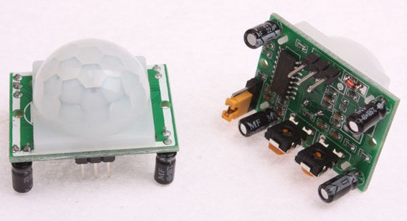
These modules are available on eBay for
$2.00 (post free !!!!!!)
Bike Flasher
Here is an example of an over-designed circuit. Not only does the circuit use
too many components, but the cost is high and the 9v battery is expensive.
A 9v battery has the same energy as an AA cell.
You may think the LED is up-side-down but the pin 7 turns on and illuminates the
LED but there is no limiting resistor.
Capacitor C2 charges
through resistor R2 and diode
D1. When the voltage across
C2 reaches two-third of the
supply voltage, threshold pin 7
of IC1 switches on as a current
sink. The capacitor discharges
through LED1 into pin 7
rapidly. Diode 1N4148 (D1)
provides the one-way charging path
for capacitor C2 via resistor R2. LED1
illuminates briefly for a while with the
accumulated charges in C2. Again, the
charging cycle repeats. This way, LED
continues flashing. A 9V PP3 battery
can be used.
Here is a simpler, cheaper circuit. It uses a single AA or AAA cell:
Before you put a circuit into a magazine, you need to check all the available
circuits and see what has been done.
Here's a badly designed circuit from
electronicsproject.org:
Pin 1 of the IC is floating. The output could be HIGH or LOW and the circuit
will false-trigger.
Pin 13 is floating.
It is a very bad arrangement to use 10M resistors as any moisture on the PC
board will change the resistance of the circuit.
The 10u across the speaker will reduce the output.
There is no way to determine if the circuit will work until these two faults are
corrected.
A badly designed circuit by someone who knows nothing about electronics.
Here's a circuit from
electronicsproject.org:
The circuit is completely different to all the FM transmitter we have presented
on our website.
The circuit above is a common-emitter stage and does not have the good
performance of a common-base circuit as descried in our designs.
However it would be a good idea to build the circuit and see how it performs.
The top 10n is not needed as the emitter is held rigid by the lower 10n.
10p on the base does nothing.
Use one of our Field Strength Meters to
determine the output power.
D. Mohan Kumar M.Sc., M.Phil, is an Associate Professor from Trivandrum, Kerala,
India. He has been producing faulty electronic circuits ever since he started
putting his rubbish on the web.
He has been told for the past two years about his junk circuits but he keeps
displaying his total lack of electronics knowledge and messing up all those who
visit his site. It is no wonder Indian hobbyists are incapable of designing
anything electronic. They have total idiots teaching in the Universities.
IR RECEIVER
This circuit will never work.
Pin 2 will never go LOW. The two 1k resistors will keep pin 2 above 50% and it
has to reach 35% to trigger the 555.
Another untried and untested circuit from Professor Mohan Kumar.
Another circuit from Professor Mohan Kumar:
The bridge has the positive going to the 0v rail.
There is no need for the 5v1 zener diodes.
They can be removed and the pots re-adjusted to produce the same effect.
The protection diode is not needed because the relay is being turned off very
slowly.
See our simpler circuit in 200
Transistor Circuits.
Here's technical mistake from one of the electronics forums from Eliminator.
He says:
"actually any ordinary transformer having current rating 1/10th of battery AH and
voltage a little higher than the battery specs will work perfectly for charging
all lead acid batteries�..that�s as simple as it can be."
He is saying an ordinary transformer can be connected directly to a battery
without any current-limiting resistor.
Firstly, where can you get "an ordinary transformer" with an output
voltage suitable for a 12v battery charger ???
Why do you think battery-charger transformers are accurate to half-a-turn?
Charging a battery is very similar to delivering a voltage to zener diode. If
the voltage is higher than the zener voltage, theoretically an infinite current
will flow.
If the voltage from the transformer (after the rectifier) is higher than the
battery voltage, a very high charge-current will flow. This can be higher than
the rating of the transformer (such as 1 amp) and can be as high as 2 - 4 amps.
This will "burn-out" the transformer.
That's why you have to be careful.
A new eBook on the market contains a lot of mistakes.
|

This is the
eBook, with the enormous
number of mistakes.
|
Click
HERE to see some of the pages of the book on the web.
Click
HERE to see some more of the pages of the book on the web.
Click
HERE
to see the remaining pages of the book
The most glaring mistake is the solar charger circuit:

The book states the solar panel is 12v @ 5 watt. This means the
panel will deliver about 400mA.
The text says the circuit limits the current to 100mA. Why waste 75% of
the generated power ????
The first mistake made by the author is the addition of the 13v zener and diode
D1. This will only allow 13.6v minus 0.7v from diode D2 to enter the battery.
This is 12.9v and the battery will never charge.
The next mistake is the 150R resistor.
A good quality 12v panel will have sufficient solar cells @ 0.56v to produce
about 18v on a sunny day.
Suppose we take away the zener diode and D1.
This means the battery will charge and generate a "floating charge" of about
15v.
If the panel generates 18v and the battery voltage is 15v plus 0.7v from diode
D2, the voltage across the 150R resistor will be 2.3v
The current through the resistor will be 15mA.
Thomas Scarborough disputes these figures. He failed to supply his own figures
and says the question is baffling.
How can a technical writer say the problem is BAFFLING ??????
He also says the book has been proof-read by qualified electronics writers and
the circuit works.
It's no wonder people are buying fewer and fewer books.
So many are filled with mistakes and when the writers are approached with a list of corrections, NOTHING GETS
DONE.
Here's the next fault:
The text states the 220u is needed to prevent the IC overheating. The
capacitance of a Piezo Sounder is about 22n. Adding a 220u will make no
difference to the output impedance. The 220u is not needed.
See our simpler circuit SONIC DETECTOR using two transistors in eBook:
200 Transistor Circuits
The graph represents a signal of about 500kHz, way beyond the capability of the
chip and the transducers.
Next mistake:
AMPLIFIER
The writer claims the LM386N-1 outputs 1 watt. The data sheet states 325mW
!!!!
Next fault:
LED TORCH
This is a totally unnecessary circuit. The supply voltage is sufficient to drive
the LED via a resistor. The circuit is simply pulsing the LED to produce a lower
output than if the LED were connected to the battery via a resistor.
Next:
CRYSTAL RADIO
What is the purpose of the 100k ???? It is not needed.
The output of the first gate is connected to ground!!!!! How do you
expect the signal from the first gate to get to the second gate !!!!
The writer claims the diode must be a germanium type due to the fact that it
only drops abut 0.3v whereas a silicon diode drops abut 0.7v.
This may be true for a normal crystal set where the voltage developed are very
small as no battery is used. But when the supply is 12v as shown in the circuit
above, ANY DIODE can be used. The text also says: Most if not all
germanium diodes should work in this circuit. All
diodes WILL WORK.
The crystal earpiece needs a resistor across it to discharge the earpiece.
This circuit shows a complete lack of understanding of electronics. Where are
the proof-readers ???
Here is another terrible mistake:
The text says: the circuit uses 6v, which is 2.4v above the typical forward voltage of a
white LED. But such LEDs will happily endure a higher forward voltage, on
condition that they are pulsed. In fact in experiments white LEDs endured
sustained testing at 10v.
This shows complete lack of understanding of LEDs.
The forward voltage for a white LED is about 3.2v to 3.6v. The actual
voltage depends on the manufacturer and the LED. If the characteristic
voltage is 3.2v, you MUST NOT supply it with a voltage above this value because
the current will increase considerably and damage the LED.
To deliver 10v to a LED is absolute madness and giving the wrong information to
beginners.
All LEDs need to have a current-limiting resistor in series. This will allow the
LED to generate its own, individual, characteristic voltage and if the resistor is the correct
value, the current will be limited to between 1mA and 17mA for normal operation
or up to 40mA for pulsed operation.
The author suggests a 10-turn 20k pot for some of the circuits.
Apart from being hard to get, this type of pot is the worst suggestion for an
experiment. It is impossible to know where the wiper is positioned and you don't
know which way the wiper is moving when you turn the screw.
And you don't need the accuracy. Just a terrible suggestion. I
avoid them like poison.
The writer has used a BAT85 diode in many of the circuits. It is a very bad
policy to use a special component when a general-purpose device will work. You
are giving the impression that the component has some special
characteristic. In the cases of the circuits in this eBook, a 1N4148 signal
diode can be used.
Another technical mistake:

JUMP COIL
L1 is a coil and the supercap 10,000u is charged via a 22R resistor. When the
switch is pressed, the energy from the supercap goes to the coil to make a metal
disc jump.
The 18v is made from two 9v batteries. The 22R resistor is too low. It should
be 220R so the switch can be pressed briefly and the battery will not have to
supply a very heavy current.
ANEMOMETER
What is a SOLAR MOTOR ??
No mention is made of the design of the solar motor, however it is basically an
AC GENERATOR.
It is also commonly called a DYNAMO and consists of a magnet rotating inside a
coil of wire. There are no brushes and as the magnet rotates, it produces a
sinewave. There is no brush-friction with this type of generator and it will
revolve with the slightest amount of wind. There is no metal core for the coil
as this would create resistance as the magnet rotates. It is actually a very
special type of generator that has no resistance to the turning of the shaft.
The following photo is a wind generator with blades. You can see the coil of
wire and the circular magnet within the housing. It would be nice to have this
explained in the eBook. (Bought at a $2.00 junk shop for $2.00)
You have to go to all different types of shops to pick up different electronic
devices. You never know where you will find something interesting. This wind
generator sticks to the outlet of your car air conditioner and spins to
illuminate a number of different-colour LEDs. Toy shops are also a source of
amazing gadgets.
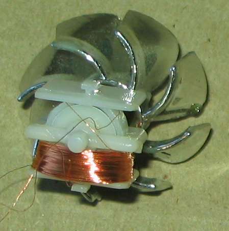
AC GENERATOR - called a DYNAMO
RELAY VIBRATOR
If the circuit is drawn clearly, you can see how the contacts work:
RELAY VIBRATOR
2-LAMP TRICK
2-LAMP TRICK
When one switch is pressed the top lamp illuminates. When the other switch is
pressed, the lower lamp illuminates.
If you press BOTH switches the two batteries will be in a SHORT-CIRCUIT state.
The circuit is badly drawn. You cannot see how the components are arranged.
The following diagram makes this clear and only uses a single 12v battery:
2 LAMP TRICK
SOLAR BATTERY CHARGER
The solar battery charger circuits presented in the eBook are over-designed. If
the battery is used each night, it will take all day to charge and providing the
current is 100mA for each A-Hr of the battery, you will not need any regulation
circuitry.
A battery will not charge when the output of the charger is 13.4v.
A battery develops a voltage across its terminals of about 14.5v to 15.5v due to
the activity within the cells and the charging voltage needs to be higher than
this to allow a current to enter the battery.
All these points are totally missed in the eBook and the writer says he has
installed systems in Africa.
He does not have a website so he doesn't know if the systems
are working correctly as he cannot get any feedback.
He says all these theoretical calculations of mine, don't apply. Who says they
are theoretical !!!!!!
This is the sort of comment I get from all the writers who have presented dodgy
circuits and if you go to the electronics forums you will find requests from
readers who have built these types of circuits and failed to get them working.
How do you think all the simulation software works???
It works on theoretical values. The gain of a certain transistor when 100mA is
flowing, cannot be worked out. It comes from known parameters that are not linear
values.
To say the charging current cannot be determined is just rubbish.
To have a writer like this in charge of a publication for beginners just shows
how little he knows about electronics.
Even the first hour of glancing though the eBook, highlighted the fact that the
writer had very little knowledge on many aspects of electronics. The fact that
he has produced lots of simple circuits is just a product of continual
experimentation. But when it comes to describing how the circuit works, the
descriptions are bemusing. How can you get a "slow oscillator" with a Schmitt
trigger gate? I think he means a low-frequency oscillator because the output
changes state very quickly. It does not matter what is happening inside the
circuit-block as the capacitor is always charging and discharging slowly. It is
the output that is described as high-frequency or low-frequency.
STYLOPHONE
Oscillator IC1a may be likened to a conventional RC (resistor-capacitor)
oscillator, except that R is largely replaced with L (inductor LSI, the
loudspeaker). An inductor works by opposing electrical pulses
(called reactance), in this case impeding the charge and discharge of C1.
TWO TECHNICAL FAULTS.
1. The resistance (and or impedance) of the speaker is so small that it has
almost no effect on adding to the resistance of the trim-pot and has almost no
effect on changing the timing circuit. The effect of the speaker is NOT a major
part of the timing circuit.
2. The timing circuit is NOT designed to impede the charging or discharging of
the capacitor by an inductor or inductance. It is purely an RC timing circuit.
STYLOPHONE CIRCUIT
ALTERNATE FLASHER
The text in the eBook is COMPLETELY WRONG:
When IC1b output pin 4 goes "low", so C2 draws a pulse through LED D2. When
IC1b output pin 4 goes "high", so C2 recharges through D1.
The correct explanation is as follows:
When IC1b output pin 4 goes HIGH capacitor C2 is not charged and it acts like a
very small value resistor. This allows current to flow through the Ultra Bright
LED D2. The 10u charges very quickly and the LED flashes for a very short period
of time.
Capacitor C2 is now fully charged and when output pin 4 goes LOW, it pushes the
negative lead of the 10u BELOW the 0v rail. This allows D1 to conduct and
discharge the 10u. It is not ready to flash the LED again when the output goes
HIGH.
Thomas Scarborough knows NOTHING about the operation of this simple circuit and
should not be producing a book for beginners and delivering FALSE INFORMATION.
ALTERNATE FLASHER CIRCUIT
VIBRATION DETECTOR
VIBRATION DETECTOR
The text says:
IC1 is wired as a standard monostable timer. It is
based on the well known 555 timer IC�however, note that this is a more sensitive
7555 CMOS version of the IC.
Why specify a CMOS version of the chip? What does the text mean by:
more sensitive? and why is it important when you have lowered the input
impedance of pin 2 to less than 500k. You can use an
ordinary 555. If the text means "low current" and you need to use a battery, a
7555 will consume about 1-2mA compared with 10mA for a 555.
This circuit is not a good design as pin 2 does not detect small changes in
voltage. The 555 is not designed for this purpose.
DELAY CIRCUIT
DELAY CIRCUIT
This circuit will only work with a MOSFET
or FET for TR1� or with a CMOS gate in the same position�since this is
essentially a static-controlled device. This circuit will not work with a common
bipolar (npn or pnp) transistor in the position of TR1, since charge, in that
case, would leak away very fast.
Some improvements need to be included to make the text in the book clear:
The voltage on the 100u will not rise above 0.7v if an ordinary transistor is
included because the base-emitter voltage never rises above 0.7v.
DOG BARK STOPPER
The drive-current for each output of a 4047 IC is
about 10mA. The output volume of this circuit will be very low and not
effective. All our Dog
Bark Stopper projects use buffer transistors
to get the maximum output. It needs nearly 1amp drive-capability of the circuit
to get a load output from a high-frequency piezo tweeter. See Dog Bark Stopper
Project.
DOG BARK STOPPER CIRCUIT
BIRD SCARER
Why use a MOSFET transistor when the
piezo transducer could be connected directly to pins 3 and 7. The output volume
will be the same - very low.
Q4 is divide by 16 and Q14 is divide by 16,000. This means you are going
to get a beep (tone) followed by the same length of time as silence.
BIRD SCARER CIRCUIT
STEPPER MOTOR
STEPPER MOTOR CIRCUIT
The two bridges are identified incorrectly. The
zener diode is not protecting the red LED from high current generated by the
stepper motor. It is merely changing the voltage at which the high-current
will start to pass through the LED and damage it. For instance, if the zener is
5v6 and the red LED has a characteristic voltage of 1.7v, as soon as the voltage
across the 0.01F supercap reaches 5.6 + 1.7 = 7.3v the LED will be damaged.
The correct circuit is as follows:
STEPPER MOTOR CIRCUIT-2
DIODE PUMP
DIODE PUMP ??
This circuit is NOT A DIODE PUMP. It needs another capacitor to "jack-up"
the incoming voltage:
DIODE PUMP CIRCUIT
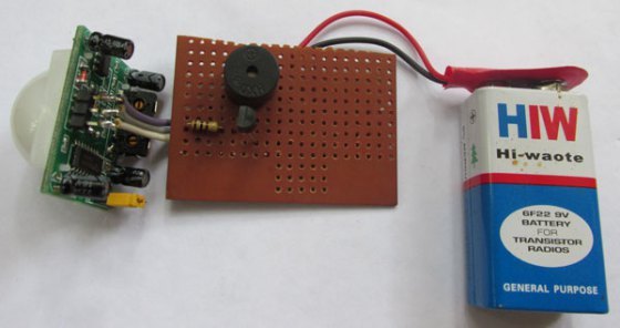
MOTION DETECTOR
This circuit does NOT WORK. An
op-amp does not work by simply putting a voltage between the input pins.
The inputs have to be biased via a resistor - either from the supply or from the
output.
White LEDs NO NOT WORK.
MOTION DETECTOR CIRCUIT
Here is the correct circuit. Almost
any op-amp can be used and the feedback resistor can be from 100k to 2M2 - it
does not make any difference.
Red LEDs and White LEDs DO NOT WORK AT ALL.
Green LEDs are quite sensitive but orange LEDs are very sensitive and
super-bright orange LEDs are extremely sensitive. Only one LED is needed.
Op-amps tried in this circuit include 741 and LM348.
LM324 was not as sensitive.
MOTION DETECTOR CIRCUIT - IT WORKS!
MAGNETIC KEY

MAGNETIC KEY CIRCUIT
This circuit does not work for the
same reasons described above. The inputs have to be biased. If the circuit does
work for a CA3130, the author should have tried a number of other op-amps to see
if the circuit is universal.
By adding the feedback resistor (biasing resistor) the inputs are biased and a
number of op-amps worked successfully.
That's why I design most of my circuits using commonly available components such
as BC547 to indicate the type of transistor is not important. The same with 555.
Just the normal 20cent item will work.
VOLTAGE SWITCH

VOLTAGE SWITCH
A light dependent resistor (LDR) causes the voltage at the control pin (ADJ)
to rise as darkness falls, causing IC1 to switch "on" and to close a reed relay.
INCORRECT
The voltage on the ADJ pin FALLS when the LDR
does not receive illumination. The circuit has never been tested and the writer
cannot "see" how it works . . . otherwise he would not make this fatal
mistake.
The output voltage changes from about 12v to about 5v as the illumination
changes from bright to dark.
How is the reed relay going to turn on and off ????? If it is a 5v reed relay,
it is still energised at 5v !!!!
If a thermistor (say 20k) is wired from the adjust pin (ADJ) to 0V, and if a
suitable resistor is wired from ADJ to +VE (say a 50k preset potentiometer, then
the regulator will switch with rising temperature.
What does he mean by SWITCH?
Where a regulator's control voltage (COM) is gradually reduced below the
minimum voltage required, in some cases the regulator will suddenly switch off.
This is true of the micro-power LP2950CZ.
This is TOTALLY FALSE. I don't know where he gets this rubbish from.
The LP2950CZ is simply a 3-terminal regulator with very low
stand-by current and less than 500mV required across it when operating. The
output can be "jacked-up" by increasing the voltage on the ADJ pin as the
regulator maintains 5v between ADJ and OUT pins.
COMPONENTS:
Most of the op-amps cost about $1.00 but the postage is exorbitant:
Mouser Electronics have op-amps for $1.08 plus $39.00 postage !!!!!
Altronics have a minimum order of $20.00
DigiKey have op-amps for $1.08 plus $34.00 postage !!!!!
RS Components have op-amps for $1.0 plus $10.00 postage.
The cheapest components stockist is: TAYDA ELECTRONICS. Postage
is $1.00 to $5.00
EBAY is also a good source for components where postage is generally FREE.
You cannot beat the Chinese!
(The Chinese, Japanese, Taiwanese, perfected the car, the transistor and
electronics in general. Of course it had a lot to do with advancement in
technology, but their attitude of making something last a long time and fixing a
fault, made them the leading edge in consumer products.)
FREE ENERGY FLASHER
The IC should be CD4016 NOT CD40106.
The circuit is drawn incorrectly. The LED is connected across the 9v supply when
the gate between pins 8 and 9 closes and the circuit is supposed to flash the
LED from the charge on the 100n.
FREE ENERGY FLASHER
CAPACITOR-FED POWER SUPPLY:
CAPACITOR-FED POWER SUPPLY
The bridge is around the wrong way!!!
The author claims it will provide 20mA from 240v AC supply.
This is INCORRECT. It will deliver 130-150mA.
How can he be so inaccurate? Simple. He has never built a capacitor-fed power
supply.
One of the dangers of describing something you know nothing about is a mistake
like this. A 2u2 means nothing to him. Whereas I have designed many power
supplies and each 100n on the input represents 7mA on the output.
The book has not been proof-read at all, with lots of spelling mistakes and
sentences missing:
The winding of the coil is by no means
critical, and a great deal of latitude is permissible. See the BFO METAL
DETECTOR for instructions on the winding of the coil, which are the same as for
this circuit. The diameter of the coil may also be changed, as described
there,
????????????? no further sentence included in the
book.
This circuit is therefore used to pulse
the LED - in this case with a one-third duty cycle (the LED is "on" for
only one-third of the time). And if the LED is "on" for only one-third of the
time,
hen of course there is a considerable power saving.
A number of circuits have the wrong IC identification: 40106 instead of 4016.
Some circuits have no IC identification.
There are lots more mistakes in the eBook. The symbol for a bridge at the
end of the book is also
labelled incorrectly, The resistor colour code at the end of the book has an extra band which I have
never seen on any resistor (this will just confuse the beginner),
The eBook says you can get a shock on 18v DC. In fact you cannot feel up
to 200v DC. But 100v AC will throw you across the room.
Another technical mistake: The solar panel may be about 5 watts upwards. While a
larger panel (say 25W)
will not provide more power, it will mean longer charge time.
Should be: While a larger panel (say 25W) will provide more power and will mean
a SHORTER charge time.
The eBook states: 500 Watts means 500 Watts for one hour, or 1 Watt for 500
hours.
No it doesn't. 500 watts can mean 500 watts for 5 minutes or 10
hours. It's like having a small radiator ON for 5 minutes or all day.
"10 Watts is ample for most relays" Relays are never rated in
WATTS. A relay has a maximum voltage and maximum
current for the contacts. You CANNOT convert these two values to watts.
Many CMOS gates (particularly Schmitt gates) switch as potential at an input
crosses one-third or two-thirds of the supply voltage. ?????
Should be: The output of many CMOS gates (particularly Schmitt gates) change
from HIGH to LOW or LOW to HIGH when the input crosses one-third or two-thirds
of the supply voltage.
If magnetic field lines approach a conductor at 90�, a current is generated
in the conductor. Further, the more turns that the conductor has, the larger the
current that is generated.
Untrue.
A larger VOLTAGE is produced with more turns. The CURRENT produced depends
on the strength of the magnet.
As with all these eBooks and faulty websites, the authors immediately come back
with a burst of comment
"I will sue you for copyright infringement."
Firstly, they know nothing about copyright law.
You are permitted to copy any work up to 20% and even a greater content when
the reproduction is for diagnosis, comment and correction.
In fact a whole work can be copied and released with all the mistakes and
comments shown in
red
as this is excluded from copyright law.
I have been involved in copyright law for the past 30 years as Technical Schools
were copying my books and handing out pages to students.
The copyright Agency in Australia then put counters on all copying machines in
schools and charged a few cents per copy. The school had to write down the
author of each photocopy. Suddenly I was sent a cheque for over $1,200 from the
Copyright Agency. As each year passed, this dwindled as fewer and fewer
schools abided by the requirement and finally we were sent a percentage of the
takings.
That's why I am well versed in Copyright Law.
But it just proved the percentage of copied works, compared to original sales,
is enormous. And it is just as relevant today as every book and magazine is available
for FREE on the web.
When you download many of these titles and glance through them, the content
is so poor, you delete the file and save $15.00.
In this day and age of being able to produce a full-colour eBook at no additional
expense, it is disappointing that no photos of any project have been included in
the eBook "6 Or Less."
A digital camera only costs $10.00.
The faulty comment made on solar battery charging makes me wonder how much the
author understands.
I go back 20 years to an article written by the technical editor of ELECTRONICS
AUSTRALIA magazine.
He made a mistake about the charging of a battery and got an enormous response
from readers.
So much so that he never wrote for the magazine again.
The mistakes made in this eBook fall into the same category.
You cannot afford to make one single mistake in electronics - especially when it
is going into print.
There are lots more typographical mistakes and the first response from the
writer should have been the inclusion of an amendments sheet in the books that
have been published and a set of corrections to the eBook.
I offered this suggestion and characteristically got no reply.
This is another eBook that I would not recommend as you don't know where the
mistakes are located and since there so many of them, you will be led "down the
garden path" with so many circuits.
The advertising spiel states: "More than 150 fast, easy, wow electronic projects."
There may be 60 circuits and the rest are just comments and adaptations of the
same circuits. This is completely false advertising.
Another false comment is: Designed with backwaters of the world in
mind: Cape Town, La Paz, Jakarta, Kolkata, and many wonderful places which may
not be that well stocked with components.
But he has used all sorts of odd and difficult to purchase components. He has
obviously raided his "parts box."
Some of the components will be impossible to find: BAT 85 diode, UN66-xx
melody chip, Solar Motor?? PICAXE-08 chip, Piezo Sounder ????, 2N2646 Uni-junction
Transistor, 6.8v 5 watt zener, 0.01F supercap, 20M 1/8th watt resistor, 100n
tantalum, 1M multi-turn pot, ICM7555IPA chip, 15M 1/8th resistor, 5v reed relay,
ICM7556IPD IC, 100p tuning capacitor, crystal earpiece, 10mm ferrite rod, and
others.
Many who live in these outreaches of the world could not afford to buy the book and they cannot purchase overseas,
anyway, so it's pointless mentioning this feature.
All the projects I design are backed by a kit of parts so no-one is left
stranded with a design that cannot be built.
I also provide a contact address and email so anyone can get further details on
a project.
Thomas Scarborough requested a right of reply, which I acceded to. But in his
last email he went on with some irrelevant drivel and it is clear he is not
capable of confronting any of the points I have brought up.
This is the sort of thing that makes me exceedingly angry.
It is a simple matter to correct the mistakes in a .pdf file. Any spelling or
omissions in any of the .pdf's on my website are corrected immediately. I don't
now how a technical writer can live with the knowledge of having faulty circuits
being circulated to hobbyists.
This shows the contempt Thomas Scarborough has for the electronics experimenter.
He produced a book with lots of mistakes and then washes his hands of the
responsibility to correct the mistakes. This eBook has the highest number of
mistakes on record and the worst descriptions.
If you think I am over-reacting, just wait until you use a piece of inaccurate
information and spend days going down the wrong path. This has happened a few
times with data sheets and you tend to double-check and triple check everything
you find on the web to prevent a problem arising again.
Thomas Scarborough emailed me to say the book is into its fourth
edition and has been checked by top electronics experts. He goes on
further to name a few of the Technical Experts:
Many if not most of the projects are from published articles, and the
proof-readers include such luminaries as (the late) John Becker, Jim Rowe, Alan Winstanley, Leo Simpson,
and Dan Danknick.
I think they would be HORRIFIED if they knew they were mentioned as having
proof-read the book or had any part of checking any of the content AT ALL.
This section of the website was a result of informing writers of the mistakes on
their site and either getting NO COMMENT or failing to fix the mistakes.
I then decided to put the mistakes on my website and now the content has grown
to more than 19 pages.
With 100 visitors reading these pages each day, it is reaching 30,000 readers
each year and been on the web for nearly 10 years.
Remember, only one in a thousand electronics hobbyists want to know and
understand the fundamentals of electronics and these pages are the first time
any writer has explained HOW and WHY a circuit does not work.
I remember employing a University graduate to build and design an oxygen
detector for a furnace, some 30 years ago.
He designed the PC board with tape and we had a sample made.
I bought all the components and he soldered them to the board.
When he put the chips onto the board he had to bend all the pins backwards and
when the displays illuminated, all the incorrect segments lit up.
The next morning he didn't turn up. I waited 'till 9:30 and rang him at
home.
He said: "Stick the project up your arse."
That's because he was told: "University students don't make mistakes!!"
It all comes from the absurd assessment of students. To get a score of 99.98%
over a range of 6 subjects, is totally stupid. It gives the student a feeling
that anything they do will be successful. This extends to their attitude when
designing a circuit.
They think: "Anything they design, WILL WORK."
The first thing they design after leaving University does not work and they
throw up their hands.
I had a second incident of "University Attitude."
A "Careers Broker" rang me to say he had a University student interested in
writing articles for Talking Electronics Magazine.
"Send him along." I said.
Oh, no. We charge $350 for a placement. (That was 2 weeks wages.)
I don't pay for placement.
3 weeks later they rang again and said they would send the applicant FOR FREE.
I contacted the applicant and said I would send him a set of parts and he could
build and describe the project.
"Oh, I don't do soldering" was his reply.
I never-again employed a University student. They simply have the wrong
attitude. University was free in those days but it took 3-4 years of study. They
all felt they DESERVE EMPLOYMENT and they all felt they could NEVER MAKE A
MISTAKE.
With scores like 85% - 95%, they think every circuit will work first-time. If
that were true, every electronics engineer would be a millionaire.
They only build circuits at University that work and test the parameters. What
an absurd way to go through a course.
As you can see, it is much more complex to produce a book of circuits, than you
think.
Every circuit has to be built by someone else to make sure it works.
That was one of the first rules of Talking Electronics.
One of the staff built each project as soon as the PC boards arrived.
But to publish a book without any form of testing or poof-reading is
madness. Nearly half the circuits in the eBook are faulty or have misleading
text. This is possibly the worst book of circuits I have come across.
Page 1
Page 2
Page 3
Page 4
Page 5
Page 6
Page 7
Page 8
Page 9
Page 10
Page 11
Page 12
Page 13
Page 14
Page 15
Page 16
Page 17
Page 18
Page 19
Page 20
Page 21
Page 22
Page 23
Page 24
|