SPOT
Page 1
Page 2
Page 3
Page 4
Page 5
Page 6
Page 7
Page 8
Page 9
These courses need to update their content and concentrate on modern materials, chips and circuitry that will be needed for present-day designs.
For a 200 watt fan, full load current = 200/240 = 0.83 Amps. Here's another incorrect response to a question in an
electronics forum: Is there any device or component that can clamp 200V to 25V
for 200ms without failure? Reply:
THE MISTAKES!
Page 21
Page 10
Page 11
Page 12
Page 13
Page 14
Page 15
Page 16
Page 17
Page 18
Page 19 Page 20
Page 22
![]()
Writing about the mistakes on the web and getting "stuck into" faults in
text books, makes you wonder what should be covered in a 3 year course on
electronics.
If I had my way, the course would start 10 years before, with the encouragement
to build at least one project a week and get it to work.
I have proof from thousands of readers who have built the kits from Talking
Electronics Magazine, that electronics can be learnt by CONSTRUCTION.
First of all, it is a much-faster way to learn and if you account the costs of a
course, it is CHEAPER.
I have talked to students after a 3 year course who "Don't do soldering."
I have University Professors who say you can achieve 3v on the base-emitter
junction of a transistor or who cannot draw the simplest circuit from memory. Or
cannot properly explain how a transistor amplifies.
I have seen graduates of an electronics course who have hardly constructed a
single electronics project.
If you look at most of the courses, they consist of stale, uninteresting,
irrelevant material such as making an XOR gate out of other gates or half-adders.
Show me one project or product using this and I will give you
$10,000. Any product needing timing or logic gates will use a microcontroller. A
flashing LED uses a microcontroller. A whistle-keyfinder uses a micro and these
cost 10cents in a $2.00 product. They use a microcontroller because it is
cheaper than using discrete components.
You can buy a fully pre-programmed PIC chip "die" for 6 cents. Obviously this is
a price (within China) for a special MCV08A (which is a much-better
version of the PIC12F629) that has been developed especially for
China. China has already ordered over 30 BILLION PIC chips - mainly
in the form of a COB for all sorts of devices, including toys and
this technology/pricing has not been released to the external
market. We are still paying exorbitant prices for a PIC chip (33
cents to
80 cents),
It should revolve around small, medium and large microcontrollers.
Then cover building blocks to interface to these devices.
Then cover chips that perform specific functions.
With this information, the student can emerge with the knowledge to design much
of the equipment for auto, health, domestic and recreational use.
In these days of high expenses for each week of study, it is pointless covering
topics that "bit the dust" 10 years ago.
But this is all the lecturer knows. That's why he keeps re-gurgitating it to the
class. One of my friends is teaching SOLAR INSTALLATION and none of the
other lecturers know anything about the subject.
YES. I am saying the complete opposite of a University course is the
ANSWER.
It's a pity mere practical skills are not recognised. The paper degree is the
almighty power.
That's why you have to bow to the powers of the recruiting officer and follow
both paths, Knowing your ability comes from experimentation; and access to the
"job Market" comes from your "CV."
You have to feel competent and capable within yourself and this comes from
actual construction and testing.
This way you won't make a fool of yourself and undertake a project way beyond
your capability.
![]()
There's an old saying:
If you can: DO
If you can't: TEACH
The whole concept of Talking Electronics website is to explain electronics to
electronics enthusiasts who want to learn electronics but
do not want the mathematics.
It would be wonderful if all electronics enthusiasts understood complex
mathematical notation, but this isn't the case.
The two understandings are diametrically opposite to being successful and it's a bit like expecting
all stunt-car drivers to be able to do tricks on a unicycle.
Now you can see what I mean.
The wonderful part of electronics allows you to build a circuit and take
"real-time" quantities and CRO observations.
These far-outweigh any hypothetical, calculated or simulated results.
The biggest problem with any new design is getting the circuit to work.
No simulation-software or text-book is going to help you.
That's why all the year's spent on the mathematical approach is going to get you
down.
The only way to learn electronics is from the bottom-up. Not from the
top-down.
I know this is a radical approach, but you should learn the mathematics AFTER
you have built and studied hundreds of circuits. The mathematics only makes
sense afterwards.
Do you know why this is not done?
Because if you build a circuit and it does not work, 99% of the instructors will
not be able to diagnose the fault.
Talk is cheap. Anyone can stand in front of a blackboard and churn out notes.
The real skill comes from diagnosing a circuit and pinpointing the fault.
I am personally against trying to work out the operating point of a circuit and
current values because all the values used in the equations are "GUESSED."
You have absolutely no idea of the current-gain of the transistor you are using
as any batch has a range that will either be double or half the guessed-values.
Why spend time working things out mathematically when the circuit will have to
be constructed and final values determined after seeing the results on a CRO.
But the biggest absurdity of most courses is the lack of basic content. The
lessons cover circuit analysis without covering any of the details of
circuit-design.
If you look at our eBook:
The
transistor Amplifier you will see over 100 circuits on designing a simple
transistor amplifier.
You cannot possibly go into analysing a circuit before learning how to design a
circuit and build at least a dozen or more circuits to see how they perform.
That's why University graduates emerge from a 3-year course without ever
touching a soldering iron.
One of the most important topics is INTERFACING. Connecting a
microcontroller to the outside world. Or interfacing ANYTHING.
Normally this involves BUFFERING the output to drive a high-current load but it
can also involve an input stage to amplify a low voltage transducer.
There are also a number of other BUILDING BLOCKS that use transistors: such as
oscillators, constant-current circuits, filters, etc and covering these is much
more important than analysing an amplifier with lots of mathematics.
These courses still have a long way to go and there are hundreds of "tricks" to
designing that I have covered in the eBooks on this website. None of these
have ever been mentioned in any class notes.
Anyone finishing a course will be be making a complete fool of themselves by
falling into simple traps that apprentices have already discovered.
That's why this website gets 7,000 visitors each day. They keep coming back for
more.
That's why you are reading this topic.
You will learn MORE in this topic than in anything anywhere else.
You learn more from other peoples mistakes - and also from your own mistakes.
And that's the factor that is missing from all the text books. They never tell
you what will happen if you use higher or lower values or what will happen if a
component is missing or goes faulty.
That's why teachers have no experience in fault-finding a students work.
That's why they don't promote the idea of building things !!
![]()
Here's an example of what I am talking about:
I've bought an industrial pedestal fan but even its lowest speed is far too windy
and noisy for my use.
The voltage is 240, at 50Hz. The fan is 200W. How can I slow it down?
To drop 100 volts at 0.83 amps, you need a capacitive reactance of 100/0.83 =
120R.
The reactance = 1/(2 x Pi X freq X C) so
C = 1/ (2 X 3.14 X 50 X 120)
C = 26.54 uF
The answer above has a major mistake. The current will not be 0.83 amps when
the capacitor is included. It will be 0.42 amps.
A 100n capacitor will pass 7mA at 240v and only 3.5mA at 120v.
To pass 0.42 amps will require 120uF.
Using the correct figures for the equation above:
For a 200 Watt fan, full load current = 200/240 = 0.83 Amps.
To drop 120 volts at 0.42 amps, you need a capacitive reactance of 120/0.42 =
285R.
The reactance = 1/(2 x Pi X freq X C) so
C = 1/ (2 X 3.14 X 50 X 285)
C = 112 uF
If the respondent to the question had built a capacitor-fed supply, he
would not make that simple mistake.
That's why construction is so important.
You will notice I have provided an alternative approach to the
MATHEMATICAL APPROACH. It's very important to approach a problem in two
different ways so you can back-up your answer.
This is the point I am trying to get across.
I am providing a second-approach to everything you are doing, so you don't make
a fool of yourself.
![]()
Loading the output WILL generate heat and 1/4W resistors just wont cut it.. you
will need to get 20W or higher resistors..
Quick calculations..
1K resistor = 40W power dissipation = 35W in the resistor & 5W in the Zener( Max
according to its Datasheet)
2K resistor = 20W power dissipation = 17.5W in the resistor & 2.5W in the Zener
(bit better, with room to breath) However at 1mA measured load (25V supply) the
Vdrop in the Resistor is 2V giving you 23V output.. (and at 10mA it's 20V,
giving you 5V output) ...
The above is absolute RUBBISH.
You just need a 24v 400mW zener diode and a current-limiting resistor. The
zener will breakdown when a minimum current flows and as the voltage rises from
0v, a low voltage will appear across the diode. As the voltage rises, this
voltage will appear at the junction of the diode (zener junction) and it will
not rise above 24v. There is a certain amount of leakage across the junction and
the voltage will not rise to 24v until a few milliamps flows.
The value of the current-limiting resistor is worked out by knowing the minimum
current required by the zener and
the data sheet specifies this as 5mA.
This means the current-limiting resistor will have 200 - 25 = 175v across it.
We do not know the the source of the 200v and some assumptions have been made
when making the following calculations:
If we want a 1 watt current-limiting resistor, it will need to be: 1 = (175 x
175)/R = 30,625 use 33k resistor
We don't know if the voltage is AC or DC but about 1 watt or 2 watt will be
sufficient.
Certainly NOT 20 watt to 40 watt !!
The original poster has now stated the source of the 200v
spike is coming from the coil in a coin comparator and we can state the current
and waveform will be so small and short that almost no energy will be delivered.
This means a 0.25 watt resistor will be suitable.
Furthermore, it is not recommended to put a zener directly across the coil as
this will inhibit the operation of the coil and prevent the received signal
providing the correct information.
Also we have not been told if the 200v signal is produced by the coil when it is
collapsing or if it is a fault in the energising circuit.
You cannot simply put a zener across the coil to limit the flyback (in the same
way as a diode is placed across a coil) because a zener is just like an ordinary
diode but with a PIV of a very low value.
If you use a zener, it will have voltage of 0.6v in one direction and 24v in the
other.
This is simply not going to work.
![]()
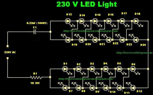
Here is a 240v LED Light:
The problem is only half the LEDs are illuminated at a time. This means you are
using twice as many LEDs to get the same brightness !!!!
![]()
CHRISTMAS STAR
The current through the 220R will be: 7v/220 = 31mA
There are 9 LEDs. Each LED will get 3mA !!
Not very bright !!
![]()
You cannot connect a regulator to a capacitor-fed power supply. (it is pointless - "waste of time")
Here's the reason:
The output of the 78L12 will be 12v. The current through the 470R will be
12v - 4v = 8v. = 8/470 = 17mA
The 78L12 takes about 3mA so the input current to the regulator will be
20mA.
The output of the power supply will be 7mA for each 100n of C1 = 33mA
The voltage on the input of the regulator will rise until it takes 33mA.
The maximum input voltage for the regulator is 35v.
The voltage will keep rising until the regulator takes 33mA and when the voltage
reaches 35v, the regulator component will explode.
You have to understand how a capacitor-fed power supply works. It is not like a
normal power supply.
We have covered this in the 30 LED Projects section.
![]()
Here's another junk circuit from ELECTRONICSHUB.ORG
The LUMILED's drop about 3.6v each. 3.6v x 5 = 18v. The supply is
only 12v !!!!!!
The circuit has never been tested !!!!
![]()
Here's another junk circuit from ELECTRONICSHUB.ORG
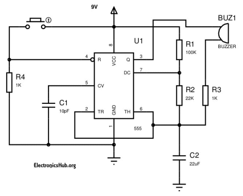
The circuit consumes 10mA when sitting around doing nothing.
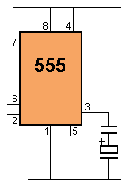
The switch should have been on pin 8 and 4.
![]()
Here's a project from Makers Shed.
Makers Shed is supposed to assist you in building things. But this project, along with
the other projects they sell, has no circuit diagram and a very high price-tag.
The kit costs $17.00 and the postage is $21.00.
Makers Shed states: New Fun Kits from Technology Will Save Us! I
don't think $38.00 will save us !!

Here is the circuit diagram, generated from the pictures of the circuit board:
![]()
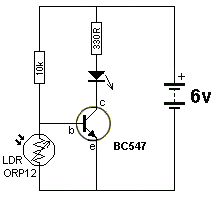
This is a really STUPID circuit:
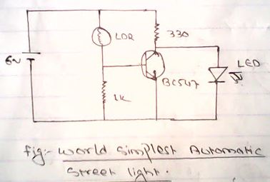
More current flows when the LED is not illuminated because the transistor is
diverting the current and WASTING It.
When light falls on the LDR, the transistor is turned ON and current flows
through the collector-emitter of the transistor and turns OFF the LED.
The following circuit takes less than 1mA when not illuminated and the 10k
resistor can be increased so the circuit takes less current.
![]()
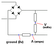
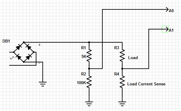
I�m trying to get real time data off of a rectifier by collecting it on a microcontroller and passing it to a computer. I am using a voltage divider to get voltage (A0 PIN) and the drop across the shunt resistor for current (A1 PIN). The problem is that when I apply rectifier I only get signal of the A1 PIN and no signal on the A0 Pin.
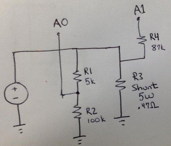
The poster on an electronics website is trying to produce a circuit that will
monitor the voltage across a load and also the current.
This is the circuit required:
Here is answer from
STEVE LAWSON:
Come to think of it, Colin�s circuit doesn�t make sense unless the
voltage divider is also the load � otherwise what current are you measuring? Or
to put it differently, why are we interested in the current flowing through the
voltage divider� it�s merely for measurement purposes.
Steve Lawson doesn't understand the concept AT ALL.
The LOAD is placed on the output terminals and the shunt resistor monitors the
current while the voltage divider resistors reduces the supply to a maximum of
5v so it can be fed into a microcontroller.
His further reply produced more lack of understanding:
This is a terrible circuit.
There is no reference point. The reference point is normally the 0v rail.
The voltage divider resistors are around the wrong way. You normally pick off a
small percentage of the supply voltage.
![]()

I clicked on the banner above on an electronics website and found it went to a
CYBER SQUATTING WEBSITE that wanted to sell the name for $2,000 !!!!
You can buy silconkits.com website for $15.00 from Godaddy for 2-years.
There is nothing I hate more than cyber squatters who demand outrageous prices
for websites.
Fortunately a website name is not important as most visitors come to a site via
a Google search.
It has put most of the cyber squatters out of business as they were charging up
to $30,000 for names they thought would be essential for running a business.
The most USELESS, SILLIEST invention on the web turned out to be the most
important factor in bringing it together: GOOGLE.
Without Google, the web would have been a total flop and ripe for fraudsters.
![]()
Here's a promotion from a PCB manufacturer:
Up to 64 sq. inches total
(1625mm) PCB for $120.00
64 square inches is an area. 1625mm is a LINE with NO DIMENSIONS.
64 square inches is equal to 64 x 25.4 x 25.4 = 41,290 square mm (mm2).
or if it is say 8 inches x 8 inches or 20.32cm x 20.32cm or 412 square cm (cm2).
If you can keep your PCB to within 100mm x 100mm, the cost of producing 10
boards is $20.00 including postage from:
http://www.elecrow.com/ This includes double sided boards,
1.6mm green, HASL and only a single routing around the board. If you have two
PCBs on the 100mm x 100mm, the item is called a PANEL and you have to allow 70
thou between boards so you can cut them apart yourself with a hax-saw and linish
the edges with sandpaper.
Both David and Martin from Elecrow provide assembly for your boards at amazingly
low prices. 3 cents for each pad of a surface mount device plus
$10.00 for set-up and $20.00 for a glue-stencil for surface-mounting. They will
supply components for a minimum of 100 boards and this is quicker, neater and
easier than trying to assemble the boards yourself.
Obviously you get a sample of 10 boards yourself and prove the circuit works.
But after that, the production is left to Elecrow for an absolutely professional
result.
Send a photo of your final project to us for inclusion in this article.
We are getting about 3 boards a week from Elecrow, as one idea generates another
and you never run out of ideas.
![]()
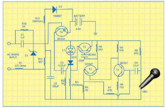
Here we have the Indian magazine AGAIN, producing the most dangerous circuit on
the market.
The neutral lead is connected directly to the microphone.
there will be very little insulation inside the microphone and if the mains
leads are connected around the other way, the microphone will be 340v LIVE. Yes,
the shock will be 340v. And if you are holding the microphone firmly, the shock
will kill you.
This type of circuit has been banned from western magazines for over 10 years.
It's about time the Indians stopped producing any type of capacitor-fed supplies
as we have already covered their dangers.
All the circuit does is turn on a LED. It only needs a few parts to do this. NOT
a circuit connected to the mains.
![]()
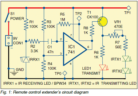
This is one point that has never been mentioned before.
You cannot put 100mA through a mini trim-pot. When the pot is turned fully
clockwise, the resistance is very low and about 100mA will flow to the two IR
LEDs. The contact of the wiper on the track will not reliably pass 100mA.
It will burn a spot on the track and go open-circuit.
This is a point worth remembering.
The solution is to just use the 56R or decide on what level of current you need
and use a fixed resistor.
Most IR controllers work to 10 metres. How far from the TV are
you?
This circuit just needs 2 transistors and few components -
not an op-amp, but that's another story.
![]()
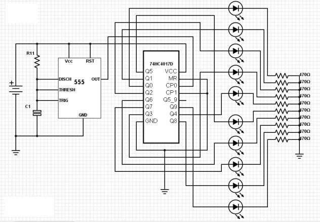
You only need 1 x 470R as only one output is high at a time.
A very poor design. No pin numbers, no component values and no understanding of
how to lay-out a circuit.
A circuit is NOT a diagram to correspond with pin numbering.
It is a diagram with the least number of "jumpers" - to make the circuit as easy
as possible to understand.
People without this understanding should not be presenting circuits on the web.
You should be able to see the output of the 555 connects to the clock-input of
the 4017 and each output of the 4017 goes incrementally to the set of LEDs.
There should be almost NO lines that cross. That's the skill of presenting a
simple circuit. The layout is just a JUMBLE.
![]()
This circuit could be very clever or a complete waste of time. But looking at
the design, the 4017 outputs Q0 when turned ON and thus the 1k current-limit
resistor on the output LEDs has no voltage across it and the voltage divider
into the clock of the chip is 1k:100k and thus the clock-line will not go HIGH
and the 4017 will not clock.
This circuit is just a MESS and you should NEVER draw chips a block but rather
as gates and the 4017 should just have all the outputs on one side to make it
easy to see what is happening.
Also, the circuit is too large to fit on the screen and this makes it very
difficult to see the whole circuit. Here is the circuit. Click on the circuit
for FULL SIZE.
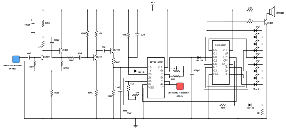
How much volume will you get out of a BUZZER with 33k in series ????
It only needs one or two mistakes and a circuit will NOT work. The author is not locatable to solve these problems so I suggest
the circuit
should be avoided.
It is debatable if 4 transistors are needed on the front-end. The fourth
transistor is just an emitter-follower and this type of stage is needed when the
output needs to drive into a low-impedance load. The input of a chip is very
high impedance this stage can be removed.
There may be a lot of other unnecessary components but until you draw the chip
as a set of gates, it is impossible to work out what is happening.
That's why I say the author of this circuit has absolutely no comprehension of
electronics.
The whole idea of electronics is to make a complex circuit "look simple."
That's how you get others to understands it.
That's the skill of presenting a project.
That's why I don't use any complex terminology. It only steers reader away.
So many text books turn a simple design into a Boolean Expression - it's
no-wonder they lose their readers with frustration.
The same with the circuit above. If it is simplified and drawn to fit the page,
the reader can see what is happening. At the moment, even
QUIZ MASTER
Here's another over-designed circuit from ELECTRONICS FOR YOU July 2014:
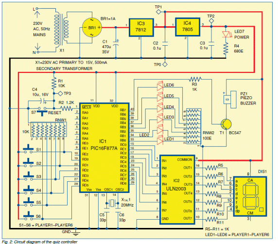
The
output of the microcontroller goes to a row of LEDs and 100R resistors. The
current will be over 32mA for a chip that has a maximum of 25mA per drive-line.
What is the point of including the ULN2003 chip when the current for each
segment is about 10mA? The chip is capable of supplying up to 25mA per
segment.
Why use a crystal? Who needs accurate timing?
The 7812 regulator is not needed.
The transformer should be 0-9v and the power LED with 680R will be very dull.
Just a badly designed circuit form Dr D.K. Kaushik and Ashok Sharma who
know very little about circuit-designing. Dr D.K. Kaushik is principal and Ashok
Sharma is technical assistant at Manohar Memorial (P.G.)
College, Fatehabad (Haryana).
![]()
Here is another FAILURE from ELECTRONICS FOR YOU July 2014:
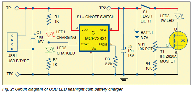
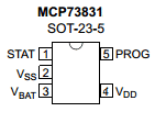
STATUS pin to drive LED1 and LED2.
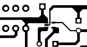
Here is the trackwork
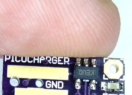
around the BATTERY MANAGEMENT CHIP
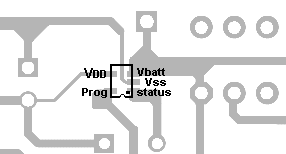
When the board is turned over, the chip
is soldered as shown above.
There is no such MOSFET as IRFZ820A. It is IRF820A. But when you look at
the specifications, it is the wrong MOSFET to use.
The minimum ON resistance between Drain and Source is
The LED will not take its full rated current and the MOSFET is not required.
The MOSFET should be something like IRF20 with an on-resistance of less than 0.1 ohm.
It's just another UNTRIED project from someone who does not know sufficient about electronics to put a project into an electronics magazine.
You can buy the chip for 80 cents at an electronics supplier (plus $10.00 shipping) or up to 20 chips on eBay for $4.00 including shipping !! That's why you cannot beat eBay !!
![]()
Here is another circuit from ELECTRONICS FOR YOU July 2014, with mistakes:
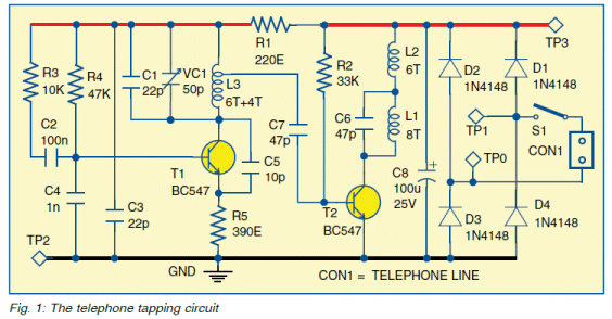
This is a copy of my circuit, which I designed over 20 years ago.
I can see some of the features I designed that are different to any other
circuit.
But the circuit has two major faults. The 22p should be 22n and the inductor L2
has no effect as the main amplitude of the signal appears at the collector of
the output transistor and the inductor is designed to keep the output tank
circuit (L1 and C6) from the power rail to produce a very high output. In the
circuit above, the inductor is simply reducing the output to the line.
Obviously the author has absolutely no idea what he is designing and it's just a
"Copy and Show" project.
The other major fault is connecting the project across (parallel to) the
telephone line.
Although the line is about 8v to 15v when the handset is lifted, this voltage
will be pulled down even further when the circuit is connected in parallel.
The "bug" should be connected in SERIES as the phone line has enough
voltage (50v supply) to allow the phone and bug to be connected in series.
The voltage and current of a phone line is complex, because the 50v supply is
classified as a HIGH IMPEDANCE SOURCE.
In other words it is a 50v supply with a low-current capability.
The 50v supply has a relay at the exchange with a coil resistance of 1k. It is a
special type of relay called a slugged relay. It is activated quickly but
does not release quickly. This allows the line to be "held" when the decadic
pulses are sent down the line. This is the "old type" of dialing with the
"turn-the-dial" or "rotary dialler" that opened the line ten times per second to
dial the phone number.
This relay does two things. It limits the current to 50mA and activates when the
current is more than 10mA.
Another relay (called a step-by-step) detects these pulses and produces a result
of the first two numbers. In other words it selects a line after a choice of one
hundred possibilities.
This is all old technology but the exchange still delivers the same impedance to
your phone and the short-circuit current is up to 50mA and the operating current
is about 20mA - 30mA.
Putting the "bug" in parallel is an absolute disaster.
It " hogs the line" and does not allow the phone to "hang-up."
Unless you have studied the phone line and studied FM circuits, you are making a
FOOL or yourself, when presenting a project.
The author has absolutely no idea about series and parallel connection on a
complex set-up such as a phone line and no idea what he is doing with FM
transmitters.
![]()
Here is another circuit from ELECTRONICS FOR YOU July 2014:
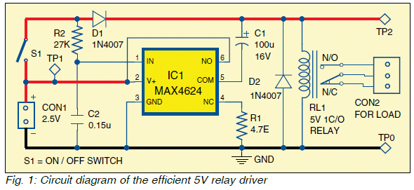
The circuit drives a 5v relay from 2.5v.
Where can you get a 2.5v supply ?????
Instead of messing around with a complex circuit, you can get a 1.2v solid state
relay for $4.00.
The relay requires about 20mA to "turn ON" so you will need a resistor in series
with the input pin to limit the current to 20mA. The two input pins are marked
positive and 0v because they connect DIRECTLY to a LED. The input current
illuminates the LED and activates a light-detecting TRIAC. The characteristic
voltage-drop across the LED is between 1.2v and when the current reaches 50mA,
the voltage-drop is 1.4v. This means you MUST include a current-limiting
resistor to limit the current to between 20mA and 50mA. The relay will turn on
at 8mA, but you should test it before using this low value. This will allow you
to use a supply voltage form 1.2v to 5v or more.
The MAX4624 is a 16-pin surface mount chip.
The max4625 is 8-pin surface mount and costs $4.60 plus postage.
Just another disastrous circuit from EFY.
![]()
To Sani Theo,
Technical Editor,
Electronics For You
Yes, of course I am annoyed.
All the Australian and English magazines publish any corrections and mistakes to
circuits BUT you fail to inform your readers of the DISASTROUS mistakes.
You don't even have the intelligence to pass the mistakes to the authors of
these articles and get a response.
Thank goodness you have stopped Professor Mohan Kumar supplying projects.

His projects were riddled with mistakes and I have finally got him banned from
supplying articles to electronics forums.
You have got to improve your editing of projects and get an EXPERT to analyse
them before publication.
I have monitored the building of the projects in EFY for the past 12 months and
found the construction to be virtually ZERO.
Everyone I contacted found the projects DO NOT WORK.
And it is NO WONDER.
Who do you think you are trying to FOOL ??
No-one in the Western world takes any of the projects seriously and this is
borne out by the fact that so few subscribe to the magazine.
Unless you improve the quality of the simple projects, you will NEVER get any
respect.
I have not even bothered to look at the more-complex projects because they
mostly involve a microcontroller I do not purchase.
But if the simple projects are not constructed, I suspect the more advanced
projects are avoided too.
Your Kit-N-Spares section is also a disaster with projects lacking an overlay
and hand-written scribble on the PC board.
Just take a look at the boards and see what an insult they represent to the
electronics world.
Lastly, look at the postage. You want $50 USD to post a $5.00 kit ?? China posts
things for FREE !!
You (India) say(s) you want to present as an advancing technical
(technological) market and have all the technical expertise to take-on
world-wide challenges and yet the technical contributors to the magazine show
little aptitude to quality designs and no-one has challenged the faulty
circuits.
You are fooling yourself with the technical expertise in the country and failing
to deliver a quality product to the electronics experimenter.
I am trying to protect the uninitiated beginner who looks at your faulty design
s and thinks they are the correct way to design a circuit.
I get hundreds of emails from Indian readers who visit my site and ask for
guidance. They are stagnated by the terrible lack of technical material
emanating from Indian publishing houses.
It is fortunate the internet is correcting this.
I have been sending you emails for the past 12 months on these subjects and you
have not replied. You have not updated the circuit boards, ANY of the
projects (nothing has been added for the past 12 months) and you have not changed
any of the images. Neither have you looked into postage costs for the kits.
What more can I say ???
Colin Mitchell
TALKING ELECTRONICS
![]()
This project has been on the web for 3 years and no-one has realised it DOES NOT WORK:
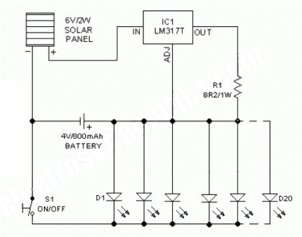
The LEDs are exactly like a 3.6v zener across the battery. They will take a lot
of current if a current-limiting resistor is not included.
Problem number two:
The 6v solar panel needs to develop 5.5v to overcome the back-voltage developed
by the battery when charging. The LM317T needs 1.5v across it and if the
charging current is 100mA, the 8R2 develops 820mV across it. This is a total of
7.8v. The 6v panel will not develop 7.8v.
The LM317 is in constant-current mode and will limit the current to 140mA but at
100mA the solar panel cannot produce enough voltage to provide any charging
current. The whole circuit is a MESS.
![]()
SOLAR CHARGER
This is another complete MESS from
D Mohankumar.
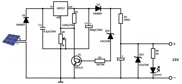
The solar panel is 24v.
The 12v zener will limit the output voltage to 12v + 1.2v =13.2v How can
you charge a 12.6v battery with 13.2v ??
Another untried, untested non-working circuit from PROFESSOR Mohan Kumar.
![]()
Battery Charger
This is one of the worst battery charger circuits I have seen.
To start with, the PNP transistor, 5v6 and string of diodes puts a zener voltage of 0.6 + 5v6 + 3v on the supply rail and if the battery is removed and the supply rises above 9.2v the transistor will be DESTROYED !!
The whole circuit is equal to a current-limiting resistor of unknown value and the circuit will effectively deliver all the current from the solar panel to the battery.
If the solar panel can deliver 20 amps, this current will flow into the battery and BLOW IT UP.
Let's see what the circuit does:
As soon as the supply reaches 9.2v, the PNP transistor turns ON and this turns ON the emitter-follower transistor Q2 and raises the gate voltage on the MOSFET.
The supply only has to rise a few more millivolts and the PNP transistor is fully turned ON and the MOSFET will be fully turned ON. So the difference between the MOSFET being not-turned-ON and fully turned ON is only a few millivolts change in the voltage on the supply rail.
Now let's look at the MOSFET.
When (if) it turns on fully, the battery is connected directly to the solar panel and the supply rail is 4.8v plus the "floating voltage" produced by the battery when it is charging.
This means the battery voltage can be as high at 5.5v.
This is not high enough to get the circuit to turn on, so the MOSFET allows the difference between 5.5v and 9.2v to be dropped across it.
This is purely a VOLTAGE DROP and you can consider the voltage drop to be identical to a zener and the MOSFET will not limit the current.
We do not know the voltage of the solar panel or its current capability and this will be the limiting factor of the circuit.
But as soon as you remove the battery, the transistor will blow up.
The first transistor only starts to come into operation when the supply reaches 5v6 + 5v5 + 0.2 + 0.6v = 12v and it is clear that the supply can NEVER go above 9.2v without blowing up the circuit.
Thus the whole circuit can be replaced with a current limiting resistor and the battery will not be destroyed.

![]()
10 MINUTE TIMER
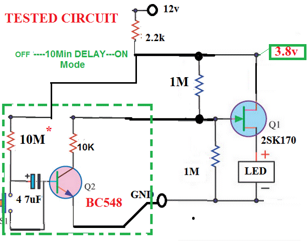
The problem with this circuit is the 10M resistor.
It is only allowing 1 microamp to flow into the base of the transistor and this
is causing two problems.
1 microamp is not enough to maintain the polarisation of the electrolytic and it
will lose its capacity over a period of time.
Because the electrolytic is not maintaining it polarisation, it will become
leaky and the leakage current will cause 1 microamp to flow AT ALL TIMES and the
circuit will never turn off.
In fact the transistor is making the circuit between 100 and 300 times WORSE by
requiring the 47u to be charged via a 10M resistor.
Without the transistor, the electrolytic could be charged via a 470k to 1M and
the timing would be 10 times more reliable.
The circuit has a SCHMITT TRIGGER action.
The uncharged capacitor turns on the transistor and the gate voltage is LOW. The
MOSFET is not turned on.
As the 47u charges, the base current falls and the transistor begins to turn
OFF. The gate voltage rises and and the MOSFET begins to turn ON. This reduces
the effective "turn-ON" voltage on the gate and the transistor continues to all
the gate voltage to rise. The MOSFET now starts to draw current and the voltage
on the top of the MOSFET starts to drop and this reduces the current through the
10M resistor. This turns the transistor off slightly and the voltage on the gate
rises at a faster rate.
This action circulates around the two components and very soon we have a
condition where the transistor is fully turned OFF and the MOSFET is fully
turned ON.
This action has not been due to the electrolytic gradually charging but the
voltage on the top of the 10M reducing from 12v to about 4v.
This action may over-ride the poor design with the 10M and by using a tantalum
or low-leakage electrolytic, the circuit may function.
However, the point still exists, not to use a 10M resistor to charge an
electrolytic.
![]()
Here we have the case of a 3v3 microcontroller turning on a LED that is connected to a 5v rail.
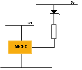
Many responders on a forum said this cannot be done and should not be done.
Others said it will damage the microcontroller and other absurdities.
The fact is this: It is quite acceptable to control the LED as shown. The LED
will have a characteristic voltage of about 1.7v to 3.6v across it before any
current flows and this means the voltage across it when the 5v rail is
delivering 5v and the output of the microcontroller is about 3.2v, will be 1.8v.
A red red will begin to turn ON and so a green or orange LED can be used. A
white LED will be ideal.
The LED will indicate two things at the same time. When it is illuminated, it
will indicate 5v rail is alive and the 3v3 microcontroller is operating.
![]()
ESR TESTER
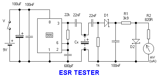
Here is a simple circuit to test if a capacitor has "dried out" or lost some of
its ability to deliver a high current.
ESR means Equivalent Series Resistance and most capacitors appear with a
Equivalent Series Resistance of a
a fraction of an ohm or a few milliohm.
In general, this value is not important and you simply compare the old electro
with a new electro and see if the reading is the same.
The circuit is a very good design and works well.
It was placed on an electronics forum and two moderators/responders,
Chuckey and
Audioguru
(with thousands of postings), gave this reply:
I replied:
Who said the capacitor is seeing a "reverse voltage" across its terminals?
The 555 has a 22n series output capacitor that has an output to the capacitor under test that swings positive THEN NEGATIVE then positive THEN NEGATIVE again over and over.
So the capacitor under test gets reverse polarity half the time unless its value is MUCH higher than 22n.
This is RUBBISH. It is amazing how a person who has been in electronics for over 30 years and replied to more than 34,000 enquiries can make such a false statement.
The problem is he cannot "see" how the circuit works.
The energy supplied to the electrolytic during the charging cycle will be removed during the discharge cycle and thus the positive lead of the electrolytic will simply increase to a small voltage and decrease to ZERO.
Here is an animation of what is happening:
Can you see any "negative" voltage entering the electro????
If you cannot see a circuit working, you have no possibility of testing,
designing and repairing it.
Simply connect the circuit your are investigating to a CRO and reduce the
timing to a low frequency and see what is happening - BEFORE making a stupid
statement on a website.
One of the amazing features of a capacitor is this: It will convert a
low-current high-voltage into a high-current low-voltage. That is exactly what
is happening here.
The result of a low-current high-voltage is called ENERGY and it requires a lot
of current to increase the voltage on the electro for each volt produced on the
leads.
That's why the small capacitor produces a high voltage across it during the
charging cycle.
The two responders are getting mixed up with a circuit consisting of a capacitor
in series with a resistor. Or a capacitor in series with a diode. When the
output of the 555 goes LOW with these two components connected, the voltage on
the lead of the capacitor DOES fall below the 0v rail.
But that's why you have to LEARN ELECTRONICS.
You cannot afford to make a mistake like this and broadcast your ignorance to
everyone else.
This is only one of many mistakes made by the posters and that's why I have
decided to monitor the forums and correct their glaring mistakes.
The most disturbing part is their inability to realise their mistake after
reading my corrections. Hopefully others will learn.
![]()
BATTERY VOLTAGE
Here's another mistake from Audioguru
"A 12V lead-acid battery that measures 12.5V with no load is almost dead."
This is totally FALSE.
A 12v lead acid battery should read 12.6v after it has been charged.
During the charging process it will generate a "floating charge" or "floating voltage" up to 15v due to the resistance of the bubbles of gas and also the type of material used in the plates. This voltage is the reason why they call some batteries "maintenance free" or "sealed" because they do not produce gas bubbles until a high voltage is developed across each cell. If you keep the charging voltage below this voltage, the battery will not produce gas and can be sealed.
You cannot measure the battery voltage immediately after charging due to the "floating voltage" it shows on a voltmeter. You need to wait 10 minutes and then apply a load for a short time to settle the activity within the cells.
![]()
BLINKING LED
Here's an example of how NOT to draw a circuit:
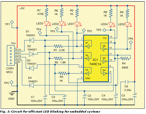
The circuit may work but it is
impossible to see how it is working. Do do not know if the blinking is coming
from the inputs or if it is generated by the components. The gates are SCHMITT
TRIGGERS and this symbol is missing from the diagram.
The basic oscillator is shown in the diagram below.
The whole diagram should show the 6 oscillator circuits so you can see if it is
gates with a low signal or a HIGH signal and see what is happening with ALL the
gates. I have absolutely NO IDEA how some of the gates are connected and a
properly laid out circuit diagram will provide these details.
This is important if you want to modify the circuit or locate a fault when the
circuit does not work.
The diagram above is absolutely USELESS. It is just a JUMBLE. It is partially a
layout diagram showing where the components are placed or how they are connected
to the chip.
That's NOT the purpose of a circuit diagram.
It is entirely designed to show HOW THE CIRCUIT WORKS. ![]()
It's hard enough to work out the operation of a 555 circuit. It's IMPOSSIBLE to
work out a 556 circuit.
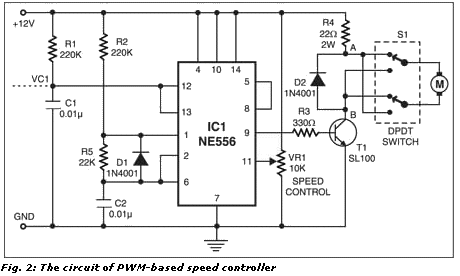
Rather than wasting time learning about the 556 chip, it is much easier to explode the 556 into two 555 circuits:
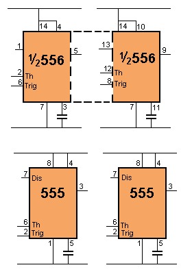
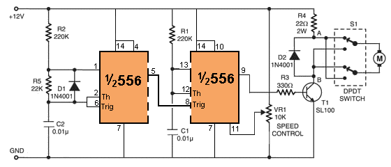
The circuit is now easy to see. All the connections are in the same places as
when using a 555. Do not be confused with pins 2 and 6 on a 556. The lower
pin (on the circuit) detects the LOW voltage and the upper pin detects the HIGH
voltage. The numbers of these pins are swapped when using a 555 / 556 and this
is very confusing.
What is the purpose of complicating things with a dual 555 when a simple 555
will provide the required mark-space ratio. There is NO SKILL in making a
complex circuit, where a simple design has already been produced.
PWM USING A 555
![]()
SPEAKER TO 555
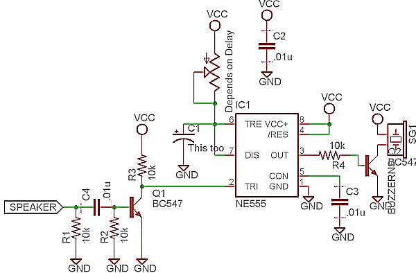
Here is a typical circuit posted on a forum. It simply DOES NOT WORK.
The circuit is supposed to detect the sound from a speaker to trigger a 555.
The output from a speaker is typically 20mV and may rise to 100mV when detecting
a loud sound. The BC547 needs at least 650mV
Resistor R1 is not needed.
The pot will be damaged with turned to zero ohms and pin 7 goes LOW.
It's circuits like these that give the web a BAD NAME.
They are untried, untested and show the designer has absolutely no idea of
electronics.
![]()
COOLING FAN
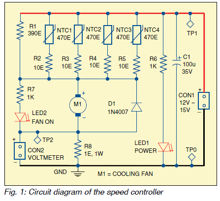
The circuit drives a cooling fan (12v 1.2w) and the negative temperature
resistors are placed on hot items. These reduce in resistance when the items
get hot and the fan increases in speed.
The fan takes 100mA when connected to the 12v supply.
The whole circuit is overdesigned and quite unnecessary, but lets look at the
absurd design.
Firstly, what is the function of R8? The text says the voltage across this
resistor will be up to 1.35v but when 100mA flows, the maximum voltage will be
100mV. !!! Why specify 1watt resistor ???
What is the function of the 10 ohm resistors?
The resistance (or impedance) of the fan is about 120 ohms.
The NTC resistors will drop to 42 ohms when all are detecting 100�C. This makes
the whole resistor network equal to about 10 ohms.
If you remove the 10 ohm resistors, the NTC resistors only have to detect an
additional 10�C to achieve the same overall resistance. Or you can use 330R NTC
resistors.
What is the function of diode D1 ?? What is it protecting ?
What is the function of LED2?? The fan will always be operating.
![]()
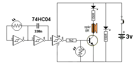
When a door opens, the transmitter sends a 40kHz signal to a receiver.
The circuit is over-designed and takes about 10mA when sitting around doing nothing. This is a waste of current the circuit needs a power supply.
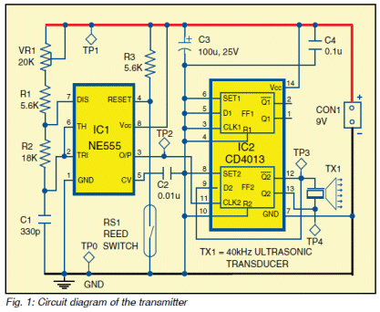
The circuit can be simplified to:
There is NO SKILL in designing a complex circuit when a simple design has
already been provided on the web.
The transistor circuit finds the natural frequency of the transducer because it
contains a crystal that resonates at 40kHz. This saves providing any timing
components and produces the highest amplitude due to resonance and the frequency
is exactly 40kHz. This is
the simplest and best design.
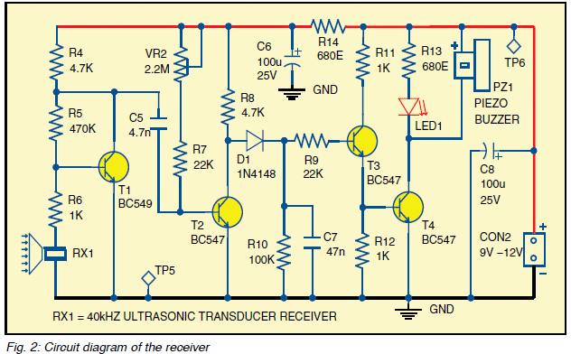
This circuit above is poorly designed and has a number of fundamental faults.
It will be very difficult to turn ON the second transistor to the point where
the collector voltage is below 1.8v, but higher than about 1v, by adjusting the
current into the base.
It needs to sit in this range for the circuit to have the best sensitivity.
If you turn the transistor ON too hard, the circuit will require a lot of energy
from the 4n7 to remove this turn-on current and turn the transistor OFF.
Don't forget, the next two transistors rely on current form the 4k7 to produce
an output. The transistor does not drive the output, the 4k7 delivers the energy
to the diode pump. It is not really a diode pump because it is really pulsed DC
and not AC driving the diode pump section.
The capacitor charges when the second transistor is turned OFF or nearly turned
OFF.
The slightest change in temperature or supply voltage will alter gain of the
second transistor and either turn it ON more to decrease the sensitivity of the
circuit or turn it OFF more and cause the circuit to false-trigger.
The next point to note is the sensitivity of the diode pump has been reduced by
the inclusion of the third transistor. This transistor is an emitter-follower
and does NOT assist in the operation of the circuit. In fact it reduces the sensitivity
of the circuit.
The diode pump is perfectly capable of turning ON the output transistor as it
only requires only a very small current into the base (less than 0.5mA) and the
4k7 will deliver this current.
The 1k on the base of the output transistor is far too low for a transistor
delivering 50mA collector current and should be 10k to 47k.
The 1k on the base of the first transistor has no effect because the 40kHz
transducer is a high impedance device so it will not increase the base to ground
impedance and the signal out of the transducer is so small that 1k will have no
effect.
The 2M2 pot should be 2M as pots are only available in 1M and 2M.
The whole circuit shows a lack of understanding of the principles of
sensitivity.
The circuit needs to be very sensitive to detect the very weak 40kHz signal and
the stages should be AC coupled to allow for variations in temperature and
supply voltage.
The second transistor should be self-biased and AC coupled to the diode pump so
no adjustment is needed.
The third transistor can be eliminated as the circuit only needs voltage gain
because the output current is only about 50mA.
The third transistor is only providing current gain, which the circuit does not
need and if the base resistor of the output transistor is increased to 10k to 47k, we
will ncrease the gain of the circuit by 10 times to 47 times.
If the second transistor is AC coupled, ALL of the signal from the 40kHz
transducer will be passed to the diode pump.
If the signal on this transistor is 1,500mV, the output will respond if the
third transistor is removed.
This requires 30mV into the base.
To get 30mV on the collector of the first transistor the transducer needs to
produce less than 1mV. I don't know how this relates to the required sensitivity
of the circuit but it represents the maximum sensitivity for the circuit and it
is AUTOMATICALLY self-adjusting and AUTOMATICALLY delivering the maximum overall
gain without any need for adjustment.
This is how to work out the requirements of the circuit.
It is a VOLTAGE REQUIRING circuit not a CURRENT REQUIRING circuit.
And secondly, it is very difficult to DC-control 2 stages. This is because each
stage has a gain of about 100 in DC conditions and 100 x 100 = 10,000. The
change in current on the base of the second transistor is being multiplied
10,000 times by the time it reaches the LOAD and picking the correct level of
DC BIAS is very difficult.
The operation of this circuit is much more-complex than you think and you need
to read our comprehensive article on
designing
transistor stages to see how to design stages
correctly.
You NEVER try to control the bias on a stage via the base resistor.
This circuit shows 4 areas of bad design and although the "circuit will work" it
is obviously not designed by a professional and not a design to be presented to
beginners in electronics.
![]()
POWER SUPPLY
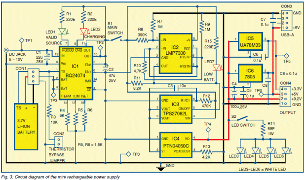
Here is another over-designed project.
Basically it will supply 3v3, 5v and 9v2 from a 3.7v Li-Ion battery.
But let's look at the design in REALISTIC TERMS.
The whole project is just an expensive way to get different voltages from a 3.7v
battery.
It uses a PTN04050C boost converter module that takes the 3.7v and converts it
to any voltage to 15v. This module costs $16.00 !!
We now take the output of this converter (9v2) to a UA78M33 - a 3.3v
linear regulator to deliver 300mA. This process wastes 70% of the energy !!!! We
are converting 3.7v to 9.2 and then reducing it to 3.3v ????
The data sheet for this IC does not tell you know the wattage dissipation for the
device and this is very deceptive as it will probably only dissipate 1 watt. Using
it on a voltage as high as 9.2v @ 300mA will dissipate 1.77 watts.
The 7805 also wastes nearly 50% in delivering its voltage and current. And this
waste ends up as heat.
For both regulators, the designer of the circuit has not provided any
mention of a heatsink and obviously does not know anything about heatsinking a
device.
Lets look at the problem.
To work out the maximum current for a 7805 with 9.2v input, the thermal
resistance is measured in degree C rise per watt. For a TO220 (7805 and uA78M33)
case the max Tj (junction temp) =125 C, and TRjc (thermal
resistance-junction to case with no heatsink) = 50 deg C/watt.
Now we can do some calculations:
The author claims the 7805 will deliver 800mA
9.2 volts input voltage, 0.8 amp load, 25 deg C ambient;
9.2 - 5 = 4.2 volts across regulator. 0.8 amps = 3.36 watts dissipation.
Temp rise, junction to ambient = 3.36 x 50 = 168 deg C.
Add ambient temp, Tjunction = 168 + 25 = 193 deg C!
The specification is 125�C max so you need a heat sink.
For the uA78M33 the wattage dissipated is 9.2 - 3.3 = 5.9 x .3 = 1.77 watts and
it will get to 115�C.
This is very hot and simply a waste of energy.
This project will cost more than $30.00 (plus shipping charges) for a something
that could be achieved with a number of rechargeable cells and two regulators.
You can buy a 18650 rechargeable battery on eBay for $1.50 each (post free) and
a charger for $2.50 (post free) that will charge 2 cells at a time. Buy 6 cells
and you will have 3 cells for the project and 3 cells being charged. These cells
are 4,000mAHr and are much larger than the 1200mAHr cell used in the project
and will last 4 times longer. By using 3 cells you have a project that will last
12 times longer at less than one quarter the cost.
It's simple ECONOMICS.
![]()
VAPORISER
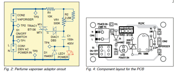
Why go to the effort of producing a PCB layout for the magazine and not provide
the trackwork for the reader?
Why not show a photo of the complete project? Because they NEVER get
the board made and never build the project. It all called "CLOUD"
designing. It's all illusionary.
![]()
 |
I have supplied over 20 major
corrections and faults to the circuits in Electronics For You and
have not received a single reply or comment from the technical editor or
any of the designers. The magazine offers $20.00 for each correction and this entitles me to $400 for my efforts. No payment has been provided to date. But the important point is this. The magazine should be including corrections and improvements in the following issues, just like the Australian magazines. This shows responsible editorship and displays an understanding that EVERYONE MAKES MISTAKES. It is fortunate that some of the "Professors" that I took to task, do not present their rubbish in the magazines any more and have desisted from presenting more of their designs on the web. Their circuits simply DID NOT WORK and one professor said the voltage between base and emitter could be as high as 3v. Obviously he has NEVER built a circuit in his life and when he saw my pages of corrections to his circuits, he pulled the plug on his website. My main aim is to cover the basics of electronics as many designers lack these concepts and when confronted, are amazed there are design-rules and tolerances that make every circuit reliable. It's funny that I don't have any disagreements with circuits designed by those with technical expertise. I am not trying to find fault with circuits that don't have a fault. I am highlighting circuits that are TECHNICALLY INCORRECT and showing how NOT to design a circuit and how NOT to make a fool of yourself. |
![]()
Electronics for You has failed to reply to my emails. The CEO has
failed to reply, the Technical "team" has failed to reply and the "Technical
Editor" has failed to reply.
Electronics for You is a LOST CAUSE.
I didn't expect a reply. They have failed to reply to any of my emails for the
past 4 years. I only expected them to fix up Kits N Spares websites where
they have the same photo for 4 different kits, images of PC boards with
"prototype" scribbled on the edge and boards with no overlay but hand-drawn
numbering.
This is an absolute disgrace and would not be accepted for a prototype shown to
electronics enthusiast. And they still want $50.00 postage for a $3.00 kit.
It is obvious they don't get any overseas enquiries. Who is going to pay $55.00
for junk kit.
They have removed their electronics forum and sale of components. The forum was
so messy and so under-used that you could not follow any of the requests.
If you look-up webtraffic:
http://urlm.co/www.electronicsforu.com you will find their penetration
outside India is 3.9% !!! It speaks for itself. They have been on the web for 17
years and only have a visitor tally that is twice Talking Electronics.
They claim a readership of 100,000 but they are selling their subscription for
half-price and including a soldering kit, so they are effectively making no
money on the subscriptions.
They can only do this to try and maintain readership to produce phony readership
figures for the advertisers.
It's sad they don't have any respect for their hobbyist market. But they simply
do not have any technical personnel to improve the website or provide any
technical information. They can only come up with stupid replies such as: "we
can post your corrections on our website after we publish our circuits."
I offered to review the articles BEFORE publication so the terrible designs
would not be published. They obviously did not understand my offer.
You can tell you are talking to an absolute IDIOT when he says he has found your
email in his SPAM folder.
This is the sort of intelligence you are talking-to at EFY. Why have a
SPAM folder where you can miss important emails ???
There are some people you can help and there are some people you CANNOT help.
After 4 years of sending them corrections to their circuits, they have still
failed to "pull themselves out of the mess."
I contacted their advertisers and distributors and did not get one single
satisfied customer. They are all paying enormous amounts each month for
advertising, with little or
no return. But they are all living in the hope that next month will
improve. WISHFUL THINKING.
![]()
Here is a statement from Electronics for You website:
Nearly 75% of the engineers passing out from various institutes are
unemployable as they are severely deficient in practical hands-on training.
This confirms what I have been saying for years. It is too late to enter
a course to get training.
Training starts at home when you are 8 years old.
Training starts with making projects. Lots of projects. It is the ONLY way
to learn.
Electronics for You provides a Basic Electronics courses at a cost of 8 days
salary for a 2-day course and a PCB design course showing how to make a
single-sided board for a power supply.
A comment from a student: "I
would also like to take up an advanced PCB design course with some training on
2-layer and 4-layer PCBs, which is currently the need in the semiconductor
industry�
What is the purpose of the PCB training course???? Who designs single-sided
boards???
I use 40 year-old CAD package because it is simple to use and does not
"fall-over."
I can also combine boards from 20 years ago when making a panel.
You must use a package that is not frustrating.
On top of this you must use a PCB maker that is CHEAP.
I pay $2.00 per board for 10cm x 10cm and get 10 boards. Some manufacturers
charge $20.00 per board. This is a RIP OFF. Every board is double-sided, PTH and
silk screened. Every board is perfect. Cheap boards are absolutely perfect and
anyone who says differently does not know what they are talking about.
I produced the first magazine in Australia to present projects using tinned
boards with solder mask and legend.
All the other magazines sold bare copper boards with no overlay!!!!!
That's how far things have come.
![]()
Here's the clincher. I sent
Electronics for You 4 articles and the reply was: "most
of them are written for those who are beginners w.r.t. microcontrollers, and the
applications discussed have already been published though through a separate
design."
I don't know where he gets that STUPID comment from. None of my projects have
even been presented before and no-one has explained how the circuits work to the
extent of my description.
When you get IDIOTS like that being in charge of areas that are beyond their
capability, you get a magazine that fails to deliver anything but JUNK.
The 3.9% acceptance by the rest of the world is an indication of how it is
viewed. Even after 17 years of publishing, it cannot get a following that
represents a percentage.
![]()
This is the sort of email I get every day from visitors to the site:
Dear Dr Mitchell,
I am teaching myself electronics and have been using your materials (pdf) on
your website. I am writing to thank you for all that you have done in preparing
these excellent teaching materials as an investment that benefits others.
When I was a kid I used to use the 500 in 1 electronics project kit and found it
useful. I also found that while there are books out there (on Amazon) that teach
electronics they tend to be very focused on the behaviour of each component and
discuss them in depth. Though this is valuable I don't think it helps to teach
how to construct circuits as a whole based on a problem or a requirement. I find
you teaching materials such as 'transistor circuits' useful and like the step by
step approach.
This message is also to encourage you and to show my appreciation.
Sincerely,
Marc Edwards
Marc R EdwardsResearch Officer
Advanced Medical Imaging and Visualization Unit
Bangor University
I am not a Doctor, nor a Professor nor do I profess to know more than 1% of the
electronics scene. But what I know is being delivered to you in a way that EVERYBODY
can understand and showing how to "see" a circuit operating so you can analyse,
test, design and FIX it.
I offered the same explanations to the management at Electronics for You
and they refused to partake in any way.
Imagine the annoyance of the subscribers to the magazine if they knew they were
being denied decent explanations and only being offered RUBBISH circuits that
have been designed by incompetent muddlers and thrown into the magazine by
"technical" staff that don't know a thing about electronics.
That's the only thing that disappoints me.
But it's the same throughout the world with doctors, politicians, banks and the
courts.
They are ALL corrupt and everything they do and say is incorrect.
If you only knew the truth you would be horrified.
I have added a lot of my comment on these subjects in
SPEED READING.
![]()
Page 1
Page 2
Page 3
Page 4
Page 5
Page 6
Page 7
Page 8
Page 9
Page 10
Page 11
Page 12
Page 13
Page 14
Page 15
Page 16
Page 17
Page 18
Page 19
Page 20
Page 22
