|
HOW A CAPACITOR WORKS |
|
|
There are hundreds of
different types of capacitors
THEY ALL WORK THE SAME.
They are ALL similar to a RECHARGEABLE BATTERY.
A capacitor takes time to charge.
A rechargeable battery takes time to charge.
A miniature rechargeable battery stores 10,000 times more energy than
the same-size capacitor, but they are both very similar as they both
store "electricity - energy."
Of course there are lots of differences between a battery and a
capacitor, but this discussion is designed to simplify HOW A
CAPACITOR WORKS as some capacitors are "jumping up and down" in a circuit while
being charged and discharged while others are just "sitting" and being
charged and discharged. It all depends where they are located in a
circuit.
Some capacitors pass a signal from one stage to the next (these are
"jumping up and down" while others
reduce the amplitude of a signal (called smoothing or filtering).
A capacitor takes a period of time to charge (and discharge) and
this time is detected by a circuit to produce an OSCILLATOR. It is the
basis of a circuit called a TIME DELAY and needs a resistor in series
with the capacitor to produce the time delay.
A capacitor can create a waveform OUT OF NO-WHERE when combined with an
inductor (coil) and this amazing capability produces another type of
oscillator - called a sine-wave oscillator.
In fact a capacitor can perform more than 10 different functions and
produce many different effects and that's why you need to read this article so you can
determine what each capacitor is "doing" in a circuit.
You may have a circuit with 10 capacitors and each is
performing a different function. You need to know what
each is doing and if it is "standing still" or "jumping up and
down."
That's one of the first things you need to know when looking at a circuit
to
"see" how it is operating.
When you can "see" a capacitor "rising and falling" you can see how
energy it is passing from one lead of the capacitor to the other by looking at the value
of the surrounding components.
That's why anyone who draws a circuit without component values ON THE
CIRCUIT is not a real electronics engineer. He obviously cannot see a
circuit working and that's why the component values are of no
importance.
The skill of being able to "see" a capacitor "jumping up and down" in a
circuit has never been described before in any text book or covered in
any lecture and that's why so few people really understand how a circuit
works.
This concept is what makes Tesla, Armstrong and other pioneers so
brilliant. They could see the circuit working and they how they
"thought-of" and improved the design.
They didn't have any text books to refer-to, they had to invent the
circuit.
That's why we have included animations. They show how the capacitor
works.
CAPACITOR SAMPLES:
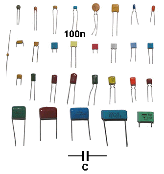
Different types of capacitor and symbol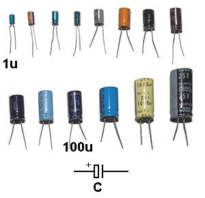
Electrolytics
When a capacitor is combined with a resistor or inductor, other effects
can be produced.
Here are some of the effects:
1. It can charge and discharge slowly via a resistor. This is called a
timing circuit or delay circuit.
2. It can prevent a waveform rising or falling quickly, just like a
"shock absorber" in a car.
This is called a reservoir capacitor or "spike prevention" capacitor.
3. It can pass a waveform from one part of a circuit to another.
This is called a coupling capacitor.
4. It can produce a waveform (called a sinewave) when connected to a
coil (called and inductor).
5. It can store energy and release it when required.
This is called a reservoir capacitor
(electrolytic).
In other words, it can do lots of things and that's what we will study.
CAPACITOR SYMBOL
The symbol for a capacitor is two parallel lines with a space between
the lines. This is exactly what a capacitor is: two plates that do not
touch.
There are slightly different variations on this to show a "normal"
capacitor (generally a capacitor from 1p (1 picrofard) to 1 microfarad -
1u and made by interleaving aluminium foil between paper, plastic or
mica). These are also called non-polarised capacitors because they can
be fitted to a circuit around either way.
A polarised capacitor must be fitted so the positive lead sees a
positive voltage to keep the oxide layer inside the capacitor in good
condition.
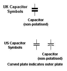
NON-POLARISED CAPACITORS
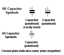
POLARISED and ELECTROLYTIC CAPACITORS
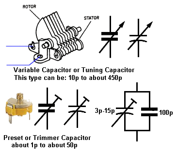
An electrolytic is a capacitor has the aluminium foil etched to increase the surface area by up to 100 times and a liquid (electrolyte) is added to contact this surface to produce the high capacitance.
A capacitor can work on its own as a STORAGE or RESERVOIR
capacitor (as explained in 3 below) or operate with a series
resistor.
When a resistor is in series with a capacitor,
the capacitor will
take a period of time to charge and discharge.
From this you can work out what is happening to the signal at the join
of the two components.
Here is how the slow-charging and slow-discharging works:
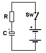
CHARGING A CAPACITOR
A battery and a capacitor are very similar. They both take time to
charge.
In most circuits a capacitor is connected in series with a resistor and
this makes the capacitor charge slowly.
As the capacitor charges, the voltage across it INCREASES but the
increase is not linear. The voltage increases quickly at the beginning but
gets slower and slower.
This looks like an amazing effect but it is really due to the voltage on
the capacitor giving the incoming voltage less "pressure" to charge it.
It is just like a man eating 15 hamburgers. He is quick at the start but
after the 13th hamburger, his full stomach slows down the eating
process.
the voltage of the battery
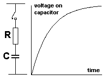
The time scale is the X-axis and if you get a perpendicular ruler and
move it across the graph at a constant speed, you will find the voltage
rises very quickly at the start and slows down as the voltage on the
capacitor increases to almost supply-voltage.
As the voltage on the capacitor rises to almost the
voltage of the battery, the increase gets slower and slower.
There is nothing magic about this.
The voltage on the capacitor is initially zero and the rail voltage will
initially deliver a high current and thus start to rapidly charge the
capacitor, as the voltage on the capacitor increases, the difference
between the rail voltage and the capacitor-voltage gets smaller and
smaller and thus the current entering the capacitor gets less and less
and thus the increase slows down.
You don't have to worry about this.
Just remember a capacitor takes time to charge (and discharge).
1b.
DISCHARGING A CAPACITOR
The discharge time for a capacitor is exactly the same as the
charge-time. If it take 5 seconds for capacitor to charge from 1v to 7v,
it will take 5 seconds to discharge back to 1v.
The discharge curve is shown in the following diagram:
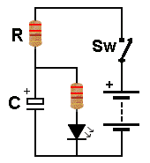
Here is a circuit using a capacitor (electrolytic) to produce a DELAY. The LED illuminates 2 seconds after the power is applied. This is a "speeded-up diagram:
3. THE RESERVOIR CAPACITOR
A capacitor can be used to reduce the oscillations on a
supply rail.
The capacitor takes time to charge and discharge and it also stores
energy when the voltage on the supply rail is HIGH and delivers
energy when the supply rail is LOW.
This produces two results. The frequency of oscillation of the
supply-rail will reduce and the amplitude of the oscillations will
reduce.
This is called STABILIZING the supply rail.
It is also called TIGHTENING UP the supply rail.
It reduces the HUM in audio amplifiers.
It reduces the spikes and glitches in digital circuits.
It is also called the FILTER capacitor.
It is also called a DECOUPLING capacitor as it prevents a spike or
glitch from one section of a circuit reaching another section.
A reservoir capacitor (electrolytic) has a HIGH VALUE so it has the
greatest effect on reducing fluctuations.
4.
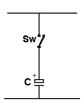
A CAPACITOR SEPARATES TWO STAGES
(in other words: A Capacitor blocks DC - it does not allow energy
to pass from one plate (lead) to the other)
The symbol for a capacitor is two lines with a space between.
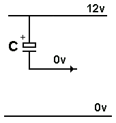
This means one plate is NOT connected to the other.
If you connect 12v to one of the plates, NO VOLTAGE will appear on the
other plate, as shown in the diagram. This diagram is showing that the
capacitor will not deliver any energy from the lead identified with an
arrow. If you connect anything to the lead, the capacitor will charge
and give a "spark" or pulse of energy BUT when it is fully charged, it will not deliver any
more energy from the
lead. This is because the two plates are not touching each other.
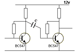
Here is a circuit with a capacitor separating two stages:

The voltage on the collector of the first transistor is
about 6v and the voltage on the base of the second transistor is about
0.6v.
These voltages are produced by the transistors and surrounding
resistors. You cannot connect these two points directly as the voltages
are different. If you connect them directly, the circuit will NOT WORK.
The capacitor connects these points and allows the signal from the first
stage to pass to the second stage, while keeping the 6v separated from
the 0.6v.
In other words: The Capacitor is BLOCKING DC.
How does the capacitor pass a signal?
It works just like a magnet on each side of a door. If you raise the
magnet on one side, the other magnet rises too.
If you raise the left lead, you increase the gap between the two plates
and energy flows into the right lead to fill the gap. The components
connected to the right-lead see this as a voltage almost identical to
what is happening to the left lead.
This is obviously only a simply way to see the circuit working, but this
is how you visualise what is happening.
Here it is:
When an electronics engineer looks at a circuit, he sees the capacitors
(and electrolytics) "jumping up and down" or "charging and discharging."
HOW DOES HE SEE THIS ???
1. If a capacitor has the negative lead connected to the 0v rail, it
will charge and discharge:
It just charges and discharges
2. If a capacitor is NOT connected directly to the 0v rail, it will JUMP UP AND DOWN.
This capacitor jumps up and down
In other words, the positive lead on the capacitor will receive a signal
and the capacitor will start to charge. Because the negative lead is not
connected to the 0v rail, it will also rise and this will make the whole
capacitor "rise" in the circuit.
During this time the voltage across the capacitor will increase and when
the signal on the positive lead reduces, the capacitor will "fall"
The voltage on the negative lead can actually go below the 0v rail and
that will be a surprise to many readers.
Here is a capacitor (electrolytic) "jumping up and down" to increase
the voltage to more than 1.7v to illuminate the LED.
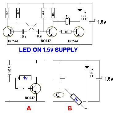
The 1u electrolytic is charged via the 100R and the
collector-emitter of the third BC547 when it is turned ON. When the
multivibrator changes state, the second transistor is turned ON and the
left-lead of the 1u is pulled towards the 0v rail.
This takes the right-lead DOWN and the 1u acts like a battery of about
1v. The right lead goes BELOW the 0v rail by about 1v and the LED see
1.5v on its anode and -1v on its cathode.
This makes a total of 2.5v across the LED. But the LED only allows a
voltage of 1.7v to appear across its leads and thus it turns on to
produce a bright flash.

Here is an oscillator circuit using a capacitor. It is
a metal detector that operates at about 100kHz and when a piece of metal
is placed near the coil, the frequency of the circuit decreases.
There are 4 capacitors. The 330p is moving up and down a very small
amount because the voltage on the base does not alter very much.
The 470p also moves up and down (sideways) by a large amount because it
is across the output of the coil and this is a sinewave with an
amplitude of about 16v. The 100n does not move up and down because one
lead is connected to the 0v rail.
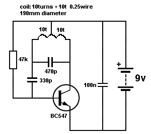
By knowing how much a capacitor jumps-up-and-down, you
can "see" a circuit working.
(in other words: A Capacitor accumulates pulses)
An Integrator is a "collector of pulses."
An INTEGRATION circuit basically takes a high voltage pulse and produces a lower voltage pulse with a wider duration.
It works like this: The energy of a pulse is the area under the pulse as shown in the diagram and this areas is spread out into a wider format with a lower height.
The shape of the resulting waveform depends on the shape of the pulses. Remember the fact that the incoming waveform charges the capacitor according to the curve above and discharges it when the input is low.
If the input consists of s number of pulses, the result can be a small DC voltage this DC may trigger another circuit.
In many cases an INTEGRATOR circuit is designed to produce and output when a number of pulses in rapid succession are detected, and neglect individual stray pulses.
A INTEGRATION circuit accumulates the incoming pulses, but the pulses must be the right shape for this to occur.
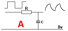
In the case of circuit A, the square wave has a HIGH equal to the LOW and the capacitor charges during the HIGH and discharges during the LOW. The result if integration is not produced.
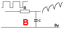
In circuit B, the HIGH has a longer duration than the LOW and the capacitor charges during the HIGH and does not have time to fully discharged during the LOW. This means the capacitor will gradually charge more and more after each pulse.
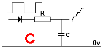
In circuit C, the "steering diode" prevents the capacitor discharging during the LOW and it gradually charges more and more after each pulse, even though the incoming waveform has an equal HIGH and LOW period.
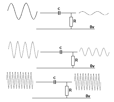
AN INTEGRATOR CIRCUIT IS A LOW PASS FILTER
In other words, the circuit only allows a low frequency to pass. To put it
another way, a high-frequency signal is ATTENUATED or REDUCED.
In the following three diagrams, the incoming frequency is increased and
you can see the output amplitude decreases.
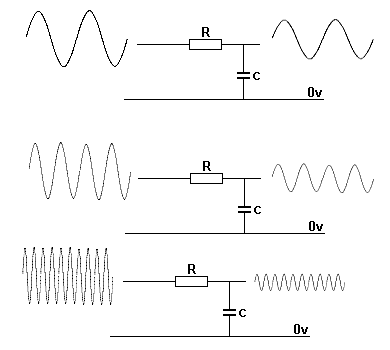
As the frequency INCREASES, the
output amplitude DECREASES
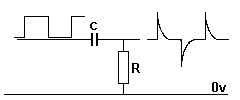
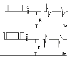
A differentiator only passes HIGH FREQUENCY signals.
The word "passes" doesn't mean the output of the differentiator is the
same as the input. It means the output signal from a high frequency will
have a good amplitude and the signal can be recognised and can be
process further.
A Differentiator only passes high frequency signals because if a
low-frequency signal is delivered to the capacitor, it will charge via
the resistor and the right-hand lead will remain at 0v. A low-frequency
signal is not a square-wave but a sine-wave or an audio wave that rises
and falls very slowly and the frequency of the signal is low for the
value of capacitor and resistor used in the circuit. The circuit is not
acting as a differentiator for sine-waves.
When a square-wave is delivered to the capacitor, the output will peak
for a very short period of time then fall, as the capacitor charges.
When the waveform drops to 0v, the charge on the capacitor creates a
NEGATIVE voltage on the output and it can go BELOW the 0v rail by an
amount almost equal to the amplitude of the square-wave.
What is the purpose of a DIFFERENTIATOR?
Suppose we have a very noisy signal from the electrodes measuring the electrical activity of the heart. This is commonly called an electromyogram signal, as shown in the following charts:
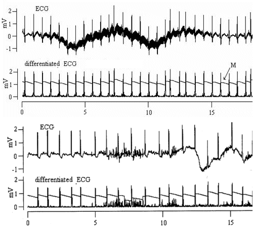
The part of the signal that we want to work-on (and
amplify) is the spikes. After differentiation, these spikes have a
common height and an additional circuit can detect them to produce a
"heart-beat-rate." A lot of the noise has been eliminated.
A DIFFERENTIATOR CIRCUIT IS A HIGH PASS FILTER
In other words it only passes high frequency signals.
As the frequency INCREASES, the
output amplitude INCREASES. With a high frequency, the voltage on the
let-lead of the capacitor is rising quickly and the capacitor does not
have time to charge via the resistor R. This means the voltage on the
left lead is the same as the right lead and thus the output has the same
amplitude as the input.
With a low frequency, the capacitor has time to charge via the resistor
and some of the amplitude of the signal is developed across the
capacitor and this amount (height) of the signal does not appear on the
output. Thus the output has a lower amplitude.
A CAPACITOR PRODUCES A SINEWAVE
If you place a capacitor and resistor in series and apply a voltage at
the connect instant and remove it at the right time, the waveform
produced at the intersection of the two components is very similar to a
sinewave.
This knowledge will help you understand what will appear at the join of
a resistor and capacitor when a pulsing, or square wave is delivered.
The result is a much-smoother version of the waveform.
That's what the capacitor does. It slows-down the rise and fall of the
waveform to produce a smooth output.
A CAPACITOR "JOINS" TWO STAGES
A capacitor can be used to "join" two stages. A STAGE is a transistor
and surrounding components to allow the transistor to operate so it is
not overloaded.
The signal enters the left-side of the stage and emerges on the right.
The stage might amplify the signal or invert it or change the shape.
This state will be connected to a previous stage and a following stage
to amplify the signal more or perform other requirements.
Sometimes one stage can be connected to another. This is called DC
coupling (DIRECT COUPLING) but sometimes the stages CANNOT be directly
coupled because the output voltage on the previous stage will be large
and the input voltage on the stage we are studying must be very small
because the transistor can only handle small voltages on the input.
In other words the AMPLITUDE of the voltages (the SIZE of the voltages)
must be kept separated.
This can be done with a capacitor.
There are two interesting points to note:
The voltage on the left-lead of the capacitor consists of two
components.
The voltage will consists of a DC component. This time the letters DC
refer to the words DIRECT CURRENT and really mean the value of voltage
that a battery would supply.
That's why we use the letters DC. Because we really mean "battery
voltage." That's why you have to learn ELECTRICAL TERMINOLOGY.
The voltage on the left-lead will also consist of a rising and falling
voltage. This is called the AC voltage or waveform.
The letters AC refer to ALTERNATING CURRENT but we just say the
letters "AC" because we really mean "WAVEFORM."
So, the voltage on the left-lead consists of two components (two
different values) AC and DC.
The capacitor will block (NOT allow the DC components to pass from the
left lead to the right lead) the DC component and allow the AC (the
waveform) to pass.
The resistor is this:
The right-lead on sees the WAVEFORM.
The transistor in the stage we are studying can now amplify this
waveform.
That's how an amplifier works.
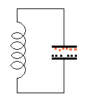
THE TUNED CIRCUIT
(TANK CIRCUIT)
When a capacitor and coil are connected in parallel and given a short
pulse of energy, they send this energy back and forth between the two
components. The capacitor is initially charged and it passes this charge
to the coil to produce magnetic flux. When the capacitor can no-longer
keep increasing the flux from the coil, the magnetic flux start to
collapse and produce a voltage in the opposite direction that charges
the capacitor in the opposite direction. This continues until the flux
can no-longer keep increasing the voltage on the capacitor and then the
the capacitor sends out its voltage to produce magnetic flux in the
opposite direction (meaning the north and south poles are reversed).
When the magnetic flux can no-longer be kept at an increasing level, the
flux starts to collapse and produce a voltage in the opposite direction
that charges the capacitor in the original direction to repeat the
cycle.
Here is how the initial charging occurs:
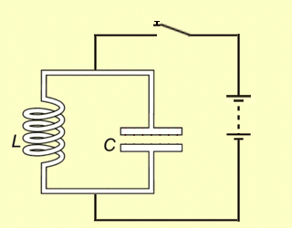
Here is how the charge continues around the circuit:
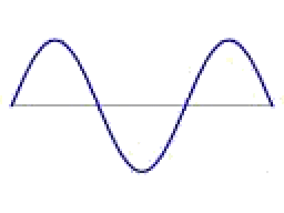
The animation above is about the closest you will get to
understanding how the energy transfers from the capacitor to the coil
and back to the capacitor aging.
The amplitude will get smaller and smaller due to losses and the switch
must be closed for a very short period of time AT THE RIGHT INSTANT for
the circuit to work.
However the result is an amazing sinewave:
THE CAPACITOR IN A CIRCUIT
In the following circuit we see three different capacitors in different situations (different applications - different reasons and different outcomes).
This is a practical application for a capacitor and here is the reason why they are used and how the value is chosen.
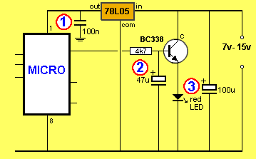
Capacitor 1 is 100n. (0.1u) and is placed near the power rails of the
microcontroller (or any IC) to prevent noise on the supply rail entering
the chip.
The capacitor also prevent any pulse produced by the chip entering the
supply rail and passing to other chips.
These pulses have a very short duration and are classified as high
frequency. A 100n capacitor will have an effect on reducing this type of
pulse.
This capacitor also produces an effect called: "tightening the power
rails" and effectively acts like a miniature battery with very low
impedance supplying current to the chip. This effect (improvement) is
very noticeable in high frequency circuits and 22n to 100n will make an
enormous difference in a circuit operating at 100MHz.
Capacitor 2 is placed on the base of the transistor and when the
transistor is turned ON via the 4k7 resistor, it gradually charge.
This causes the LED to gradually illuminate.
When the output of the micro is LOW, the capacitor gradually discharged
and the LED gradually dims.
Capacitor 3 is placed across the battery to prevent the battery
voltage dipping when the circuit requires pulses of current.
These pulses of current can be 2 to 10 times more than the average
current taken by the circuit and when the battery gets slightly
depleted, it cannot deliver this current without the voltage dropping
noticeable.
This dip in voltage will be sent to all the chips in the project and may
upset some of the waveforms.
This is especially noticeable in audio circuits where "pulses" or
"glitches" passed to the front-end of an amplifier will be amplified and
re-sent back to the front-end in a loop called "feedback."
This feedback is detected as "motor-boating" or "putt-putt-putt"
from the speaker.
HOW A CAPACITOR CHARGES IN A CIRCUIT
Just because a capacitor charges and discharges in a circuit does not mean every capacitor is "acting" the same. Some capacitors are "jumping up and down," others are charging more than another capacitor and others are producing a negative voltage.
Here are three capacitors connected to the same output of a 555 where
the output is changing from LOW to HIGH very quickly and remaining HIGH
for a period of time before returning to LOW. These diagram are not
completely accurate but give an idea of the capacitor charging and
discharging and the animation highlights the different effects when
other components are connected in series with the capacitor.
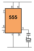
The smaller capacitor charges to a higher voltage than the larger
capacitor and at no time is any lead of a capacitor taken to below the
0v rail. (See the next animations for a negative-effect).
This effect takes a lot to understand and MANY electronics engineers get
it wrong.
The explanation is as follows: A capacitor has the amazing ability to
change a charge consisting of a high voltage with a small current into a
low voltage and high current.
Firstly we will explain what we mean: We can charge a huge electrolytic,
such as 100,000u to a voltage of say 200v over a period of 5 minutes
with a small current such as 200mA.
We can now get a spanner and short the two terminals and get an enormous
spark that welds the spanner to the contacts.
This welding process is due to the enormous current.
But we only charged the electrolytic with 200mA.
The electrolytic has changed the energy it has received from a value of
200v and 200mA into a few volts and 100 amps.
That's what ANY capacitor can do in ANY circuit and it all depends on
the value of the surrounding components.
If we take the animation above, the output of the 555 delivers a voltage
and a current to the two capacitors in series. Since they are in series,
the current through the top capacitor must be the same as the bottom
capacitor.
So, we cannot talk about different current-values.
This is the only way we can explain it: Water is flowing out pin3 of the
555 and half of it flows into the small top capacitor to fill it very
quickly while the other half flows into the large electrolytic and it
rises on very slightly.
When pin3 goes LOW, it is exactly the same as connecting the top
capacitor to the 0v rail.
The charge flows out of the capacitors at the same rate as they were
charged. In other words, both capacitors will discharge smoothly but the
discharge-time may be a lot quicker than the charge-time.
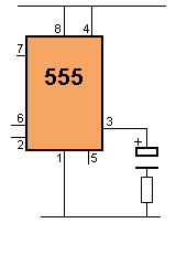
ANIMATION 2:
The following animation shows the electrolytic charging via the output
of the 555. The output actually rises very quickly and this animation
would be correct if the output rises slowly.
The point to note is this: The negative lead of the electro drops below
the 0v rail when the output goes LOW and the electro is discharged via the
resistor.
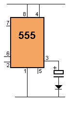
ANIMATION 3:
When a diode is connected in series with the electrolytic, it
gets fully charged on the first cycle and the negative lead goes below
the 0v rail when the output of the 555 goes LOW. The electrolytic
remains charged and does not get discharged by the diode.
|
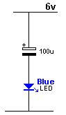
This circuit shows how a capacitor works when the negative
lead (the 0v lead) is not connected to the 0v rail. This has never been covered before and needs to be explained. The circuit consists of a 100u electrolytic and blue LED on 6v supply.
We have all been told the positive electrode of a
capacitor creates a charge and the negative electrode
creates a charge and no current passes through the capacitor
because of the gap between the plates. |
SPLIT RAIL
Here is another circuit
that requires a special way of thinking to "see" how the
electrolytics work.
Some circuits
need a voltage that is identified as 0v voltage at a
particular connection and a positive voltage and a negative
voltage.
The reason for this is the output of the circuit has a
voltage that is half-way between the voltage on the top
rails and the bottom rail and it produces a signal that
rises almost as high at the top rail and almost as low as
the bottom rail.
This means the amplifying circuit, such as an op-amp or
AMPLIFIER, requires a voltage that is equally POSITIVE and
NEGATIVE, with the earth, or chassis or neutral classified
as having zero voltage. In other words it is the reference
point (0v) for all the other voltages.
As far as the
output is concerned, the two 470u electrolytics are
connected in PARALLEL and prevent the bottom lead of the
speaker moving, when a signal is delivered to the top lead.
The do not prevent the bottom lead moving like a fixed
connection but limit the movement or restrict the movement
just like a 2 ohm resistor.
A 100Hz, the two 470u electrolytics have a resistance
(impedance) of slightly less than 2 ohms and at a higher
frequency this value is a lot less. That means most of the
signal will appear across the speaker.
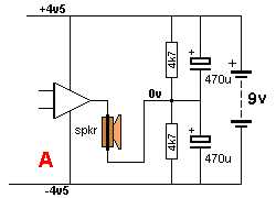
Producing a SPLIT-RAIL SUPPLY
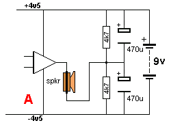
When the signal from the amplifier rises to a HIGH, the speaker
sees nearly all the amplitude. Both the 470u electros try to
hold the bottom lead of the speaker in a fixed position but one
of them charges and the other discharges slightly. This action
is reversed when the signal moves in the opposite direction.
You can see one of the electrolytics is charging and this is easy
to understand. But the other electro discharges at the same rate
and it produces the same effect on the lead of the speaker in
trying to keep it from moving.
An electrolytic is exactly the same as a shock absorber
containing oil and the oil is passed from one cylinder to
another via a very small hole. You can press very slightly on
the shock absorber and it will open or close completely. This is
the action of the 4k7 charging the electro over a long period of
time.
But if you push very hard on the shock absorber, it will only
move very slowly. This is the action of the signal (via the
speaker) on BOTH electros.
It does not matter if you are charging the electro or
discharging it. The same "resistance to movement" or
resistance to charging/discharging, applies.
Because the positive rail are classified as "unmovable" the
positive end of the top electro DOES NOT MOVE and the negative
of the bottom electro DOES NOT MOVE.
Because these ends do not move, the top electro can be taken to
the negative rail and it will have the same effect.
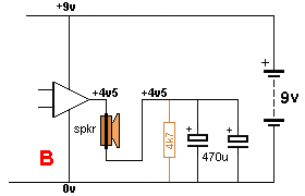
to deliver the same effect as creating a Split-Rail
The end result of the 2 x 470u electrolytics is exactly the
same as placing them in parallel to produce 1,000u. The diagram
above shows the circuit re-arranged with the two electros on the
negative rail.
The amplifier will produce an output swing of +4.5v to -4.5v and charge/discharge the two
electros so they will produce exactly the same result as in the
first circuit.
AN ELECTROLYTIC PROBLEM:
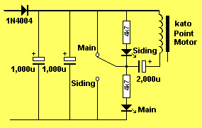
Here is a circuit called a CAPACITOR DISCHARGE UNIT. The switch
dumps the energy from a charged electrolytic into a coil to
change the point on a model railway.
The same effect can be achieved by charging an electrolytic with
the coil in series because the coil produces magnetic flux when
a current flows. It does not matter if the current is
charging a capacitor or discharging it. (the only difference
will be the North and South poles will be reversed) but that does
not concern us in this problem.
However, here's the problem:
When the switch is connected to "Main" all the energy in the
2,000u capacitor is dumped into the coil.
But the coil requires a special type of energy. It
requires a very high peak current at the beginning to produce a
high value of flux to pull the armature into the coil.
At the same time the switch is connected to "Main," the 2,000u
electrolytic gets discharged.
When the switch is connected to the "Siding" position, we have a
situation where the uncharged 2,000u is connected in series with
2 x 1,000u electrolytics and a high current will flow. This
current is much higher than can be supplied via the 1N4004 diode
and we can assume the diode is not connected, as it will not
assist.
This means an uncharged electrolytic (2,000u) is placed across a
charged electrolytic (2 x 1,000u) and these are the same value.
What happens is the uncharged electro starts to get charged and
it produces a voltage across its-self that subtracts from the
voltage across the other 2 electros and thus the flow of current
is much less than when the switch is in the "Main" position.
In addition, the voltage across the two 1,000u electros reduces
(they get discharged) and this further reduces the current. This
all happens very quickly compared to the movement of the
armature in the coil and the result is the activation is much
weaker in one direction.
It is difficult to put a figure on this but the observation is
about 50% effective.
In other words you would need 4 x 1,000u to get 75% effective
and no amount of capacitance will achieve 100%.
oooooooooooooooooooo000000000000000000000000ooooooooooooo
You will find a lot of helpful material on these pages:
Spot Mistakes: P1
P2
P3
P4 . .
P11
P12
P13
P14
P15
P16
P17
P18
P19
P20
Now go to Basic Electronics 1A:
17/4/2021
