The 555 IC is
very popular, with over 150 different circuits designed
around this 8-pin chip - so we are giving it a whole chapter.
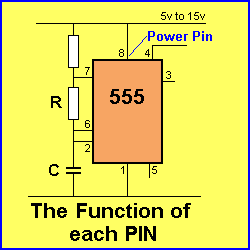
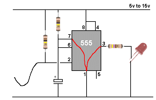
The 555 is an OSCILLATOR CHIP without the TIMING
COMPONENTS.
When you add a resistor and capacitor, you create a TIME DELAY
circuit because the capacitor takes a period of time to charge
via the resistor.
The 555 is connected to the join of these two components
and it monitors the voltage.
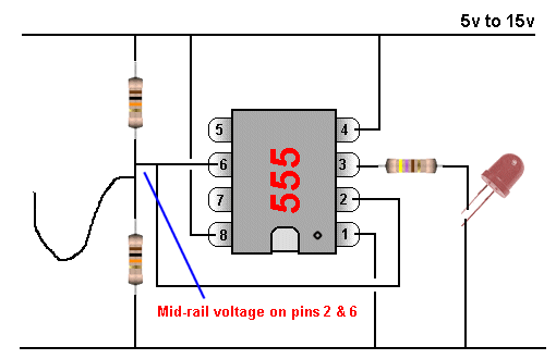
When the voltage is 2/3 of the supply voltage the chip TURNS
OFF and the output goes LOW.
The chip then removes the CHARGING VOLTAGE and connects the
resistor to 0v rail. The capacitor begins to discharge and when
the voltage is 1/3 of supply voltage, the chip TURNS ON.
The output goes HIGH and the charging resistor is
connected to rail voltage to start the cycle again.
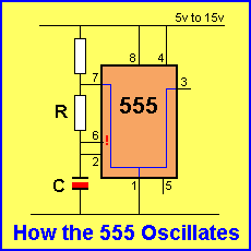
If the value of the capacitor and resistor are small (low
values) the rate at which the 555 turns ON and OFF will be fast
and the circuit is called an OSCILLATOR.
If the value of the resistor is high and the capacitor is above
say 1u, the rate at which the 555 turns ON and OFF will be low
and the circuit is called a TIMER.
The 555 can operate as a timer up to about 10 minutes and as an
oscillator up to about 300kHz.
This gives an enormous range of capabilities and that's why over
150 different projects have been designed around it.
There are a number of different 555 chips, but the cheapest is
called a TTL device due to the components inside it and it
takes about 10mA when in a circuit. There are low-current
versions called CMOS (but the output current is very small) and a 14 pin
TTL version containing two 555 devices.
We will be covering the cheapest and simplest version called:
NE555, or HA555 or, SE555, or CA555 (P package or DIP package).
Look for the price: about 25cents to 35 cents each.
eBay: 10 items for $1.20 with free postage!
NA555D or NA555P or NE555D are surface-mount. Cost: about 45
cents.
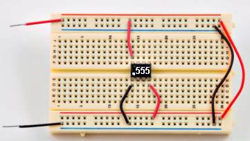
The 555 IC fitted to bread-board with
pin 1 clearly marked
with a dot.
Breadboard from eBay: $2.40 (free postage). You
must get the
breadboard with the positive and negative rails marked with red
and blue lines.
Jumpers:
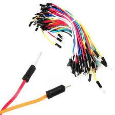 You
can also get a pack of jumpers to connect the components. eBay:
$1.70. You
can also get a pack of jumpers to connect the components. eBay:
$1.70. |