|
HOW A DIODE WORKS |
|
|
|
There is a lot of confusion in text
books and on the web about CURRENT FLOW. WHICH WAY DOES CURRENT FLOW?
Current is a flow of electrons.
These electrons are negatively charged particles and they are
attracted to the POSITIVE of the supply. This means they flow
from NEGATIVE to POSITIVE.
Don't use any text-books that say
current flow is electron-flow as they are omitting
CONVENTIONAL CURRENT FLOW and this will confuse you. |
A diode is a very
simple device and it has a lot of applications.
We will cover some of its uses and explain exactly how it works in very simple
terms.
If you don't understand any of the points in this discussion, you can
contact Colin Mitchell.
A diode is a device that passes current in only one direction. It
is a bit like a water-valve that prevents water back-flowing into the
mains from your property. Or a valve in a pump that prevents the water flowing back down a
well.
There are many types of diodes to handle small currents, large currents,
high frequencies and high voltages. And there are diodes made from
different materials, but they can all be described in a simple
way. And that's what we will do.
A diode has two leads. These are called ANODE and CATHODE.
The cathode end is
identified in a circuit diagram and
on the body of the device.
It may be identified with a line, chamfer or dimple or a symbol. There
must be something on the diode that identifies this lead and you have to
look for it.
A diode does NOT have a positive or negative end. You see this mistake
in so many discussions. A diode will have a positive voltage on the
anode and a slightly lower (positive) voltage on the cathode. It will not have a
positive on the anode and negative on the cathode.
Incorrect marking with "+" and "-"
In the following diagram only the CATHODE is identified with the letter k (for kathode). The other lead is the ANODE. And that's the only way to identify a diode. That's the professional way.
Correct marking with "k"
Here is a pictorial way to understand how a diode works:
OR
THE RESULT IS THE SAME
9v comes out of the battery and when it passes through the diode, 0.7v is LOST (dropped across the diode), resulting in 8.3v available to operate a motor etc. It does not matter if you are driving a motor or a torch globe, the device will see 8.3v But the actual voltage across the device will depend on the current flowing and it will be 8.3v or lower depending on the surface area of the junction of the diode and how much stress you are placing on the diode. If the diode is designed to pass 10 amps and the current flowing is 1 amp, the voltage across it will be 0.7v because it is not being "overloaded." But 1 amp through a 1amp diode is going to stress it enormously and the voltage across the junction can go as high as 1.1v. So, nothing is predictable and you have to build the circuit to find out.
The most common type of diode is made from SILICON. It can also be made from GERMANIUM. You need to look in the datasheet to find the composition of the diode you are using. 99% of the time it will be silicon.
A diode does not start to TURN ON until a small voltage
is present on its ANODE lead.
For a Germanium diode, this voltage is approx 0.3v.
For a Schottkey diode, this voltage is 0.3v
For a Silicon diode, this voltage is 0.7v. When the voltage on the Anode
is 0.8v, you will get 0.1v on the Cathode. And the same principle
applies with all diodes.
You must NEVER put a diode across the leads of a power supply. It will
blow up.
A diode does
not determine the amount of current flowing. The current flowing is
determined by the load (such as a motor) and the voltage of the battery.
This is a simple OHM's LAW
equation and to get an exact answer, just take 0.7v from the supply
voltage and put the values into the equation.
![]()
Question
For a diode, does current flow from anode to cathode, or cathode to
anode?
![]()
Answer
Current flows from anode to cathode. The arrow on
the symbol shows the direction of CONVENTIONAL CURRENT flow. ![]()
WE WILL TAKE THE EXAMPLE OF A
SILICON DIODE
A silicon diode is just like the wall of a dam. As soon as the water
reaches the top of the wall, it overflows. The silicon diode has a
height of 0.7v and as the voltage from the power supply increases,
nothing happens until the voltage reaches 0.7v. At this voltage CURRENT
STARTS TO FLOW and if the voltage is increased, the CURRENT INCREASES. It's just like the water flowing over
the top of the dam.
DIODE VOLTAGE NOT CONSTANT
We have said the voltage across a silicon diode is 0.7v. This voltage
increases slightly as the current increases.
For a 1 amp diode, this voltage will increase to about 1.1v when 1 amp
is flowing.
For a 3 amp diode, this voltage will increase to about 1.1v when 3amp is
flowing.
For a 10 amp diode, this voltage will increase to about 1.1v when 10 amp
is flowing.
The voltage across a diode
increases with current-flow
In the
diagrams above, the current-flow is determined by the voltage of the
Power Supply AND the current required by the load. The diode does
NOT determine the current-flow. By increasing the voltage of the
Power Supply, the current will increase.
The LOAD can be a motor, globe or high-wattage resistor.
In diagram A, the voltage drop (voltage lost) across the diode is
0.7v. This voltage increases to 1.1v in diagram D due to the
increase in current.
Because the current and voltage increases in each diagram, the
wattage (heat generated) by the diode increases at a very fast rate:
In diagram A the wattage generated by the diode is: 0.3 x
0.7 = 0.21watts
In diagram B the wattage generated by the diode is: 0.5 x
0.8 = 0.4watts
In diagram C the wattage generated by the diode is: 0.7 x
0.9 = 0.63watts
In diagram D the wattage generated by the diode is: 1.1 x 1
= 1.1watts
REVERSE VOLTAGE
If you connect a diode around the wrong way, no current will flow. But
if you increase the voltage to 100v, 200v or 300v, the diode will
suddenly break-down and a current will flow.
The voltage at which this occurs is called the REVERSE BREAKDOWN
VOLTAGE.
It could be as low as a few volts or as high as 1,000v.
This voltage is always provided in the data sheet as it is
most-important.
If a diode is used in a mains BRIDGE RECTIFIER (to be discussed later),
it will see a voltage as high as 325v for the 240v mains and the diode
will need to be a 400v device.
A 1N4004 is a 400v diode - This is
its REVERSE VOLTAGE rating
In the circuit above, the diode will not be destroyed when the voltage
reaches 400v (for a 1N4004) because the current-limiting SAFETY RESISTOR has been
included.
Question
For a silicon diode, what is the approximate voltage-drop across its
leads when it is delivering about 10% of its rated current?
![]()
Answer
0.7v This is is the voltage
we use for current up to about 40% of maximum current.
![]()
Question
Which lead of a silicon diode is identified on a circuit
diagram?
![]()
Answer
The cathode lead is identified with the
letter "k" ![]()
Question
In the following diagram, is the diode conducting?
![]()
Answer
Yes![]()
Question
In the following diagram, is the diode conducting?
![]()
Answer
No. The diode is reverse-biased. The
arrow on the diode indicates the direction of
current-flow. ![]()
Question
In the following diagram, is the diode conducting?
![]()
Answer
No. The diode is reverse-biased. The
arrow on the diode indicates the direction of
current-flow. ![]()
Question
In the following diagram, is the diode conducting?
![]()
Answer
Yes ![]()
DIODE PUZZLE
The
supply in the following two circuits is 12v. Identify the
resistors that have current flowing through them:
(answers are a little further down the page)
Here are some applications for a diode (or set of diodes):
THE DIODE AS A PROTECTION DIODE
In the following diagram, the diode does not conduct if the battery
is connected around the wrong way. It is called a PROTECTION DIODE. This
means the circuit will not see a reverse voltage and will
not be damaged.
However the circuit will see a voltage 0.7v less than the voltage of the battery
due to the 0.7v drop (lost) across the diode.
Protection diode
In the following circuit, the diode conducts if the battery is
connected around the wrong way and creates a SHORT-CIRCUIT. This will
burn-out the fuse. The diode is called a PROTECTION DIODE.
Protection diode
The advantage of this circuit is the diode does not drop 0.7v between the supply and the voltage
on the project. The full voltage of the supply is connected directly to
the project. This is a big advantage for projects working on
12v (battery) and require a high current, however the fuse will be damaged if the battery is
connected around the wrong way.
In the following diagram, describe the fault:
| Answer The diode has been drawn around the wrong way. |
| Answers
to Diode Puzzle above A, B C A C D |
THE DIODE CONVERTS AC TO DC
A diode can be used to convert AC to DC:
The diode converts AC (called ALTERNATING CURRENT) to DC (called DIRECT CURRENT).
Let's explain this more accurately. Alternating current is the name given to a voltage that rises in value and falls. The electricity supplied to your house is called AC.
One of the wires will have no voltage on it and the other wire will have a voltage that rises to a high value and then reduces to zero and then drops to a high value in the opposite direction.
This is called an ALTERNATING SUPPLY.
If you connect a diode to this wire, the voltage will rise to a high value but when it drops below zero, the diode prevents the negative voltage appearing. The result is this: You only get the positive portion of the voltage and this will be present for half a cycle and nothing will be detected for the half cycle when the voltage is below zero. The result is pulses of positive voltage with a gap between the pulses. We call the result DC but it is really PULSES OF POSITIVE VOLTAGE.
The original household voltage was 120v DC (direct current). DC is the same type of voltage that comes from a battery. It does not rise and fall but is steady at the specified voltage.
If you apply 120v DC to a 120v globe, it illuminates brightly.
You can also operate motors, toasters, heaters and other simple pieces of equipment from DC. (But you cannot operate a piece of equipment containing a transformer and that's why it has such limited use.)
And you need to locate the generator very close to each household because you cannot use transformers to deliver the supply and there is a voltage drop in the street wiring due to the current flowing in the wiring.
This needed lots of small generating plants and it was a very expensive way to deliver electricity.
The solution was to convert to AC (alternating current) and locate a single generating plant at either a source of coal or water for hydro electricity.
But since AC is rising and falling, the heat produced by 120v AC in a toaster (for example) will not be as much as 120v DC because part of the waveform is less than 120v for a portion of the cycle.
The answer was to make the 120v AC rise higher than 120v for part of the cycle so that it produced the same heat as 120v DC.
This means the 120v AC rises to 170v at its peak.
For 240v AC mains, the voltage rises to 336v.
That's why the 120v or 240v mains is so dangerous. Your body actually detects the 336v and this is what kills you.
Now, let's understand how this 120v/240v is delivered.
The mains actually consists of a single wire. This is called the ACTIVE.
The other wire is the GROUND or EARTH or NEUTRAL.
Sometimes the Neutral is also delivered as a wire, but let's take the case of a single ACTIVE wire.
The voltage in the active wire is rising 336v HIGHER than earth then it falls to 336v LOWER than earth. It is rising and falling like this 50 or 60 times per second.
Once you understand this concept, you will able to see how a diode converts AC to DC.
Placing a diode on the active line of the mains will remove the part of the waveform that falls 336v LOWER than earth.
The result is a set of 50 or 60 pulses per second that rise 336v higher than earth. In actual fact a pulse rises 336v then falls to zero. There is no waveform during the time when the original waveform falls below earth.
The following diagram shows the result of adding a diode to the active line. The result is not DC but PULSATING DC and needs to be smoothed via an electrolytic to get DC.
The following diagram shows the result of adding an electrolytic::
Using a single diode is called HALF-WAVE RECTIFICATION.
Adding an electrolytic is called SMOOTHING. It can
also be called REDUCING THE RIPPLE.
FULL WAVE RECTIFICATION
The negative portions of an AC
waveform can be combined with the positive portions to produce a pulsing DC
waveform.
See:
http://www.electronics-tutorials.ws/diode/diode_6.html
or:
http://www.eecs.tufts.edu/~dsculley/tutorial/diodes/diodes3.html
for an explanation on how the diodes in the bridge "guide" the incoming
waveform to produce pulsing DC:
When an electrolytic is added to the circuit, it charges during the peaks and delivers energy when the waveform drops. The result is called DC with Ripple.
If this circuit is not connected to a LOAD, the ripple will be almost
zero. If the load takes a small current, the ripple will be small. If
the current is large, the ripple will be very large.
DESIGNING A BRIDGE
A bridge consists of 4 identical diodes and if you want to design
a bridge that does not fail, you need to know a few points.
Firstly the HEATSINKING PROBLEM.
Diodes must be soldered close to the PC board to allow the heat produced
by the diode to be dissipated into the trackwork on the board. This is
absolutely critical and a thick track will dissipate a more heat and
keep the diode at a lower temperature.
Surface mount diodes are the best option, They are cheaper, easier to
fit, quicker to solder and
pass the heat to the board more efficiently.
Providing you have good lands around each end of the diode you can use a
higher rating diode than previously and this will reduce the
voltage-drop and the heat produced. (for instance, if you are drawing
1amp and using the old-fashioned leaded 1 amp diodes, you can now use 2
amp surface mount diodes and get a much better power supply).
For example, when you have 5 amp surface-mount diodes in a bridge, and
the current is 5amp, each diode will be passing the current for half the
time and although 5 amps will be flowing through 2 of the diodes at each
half-cycle, and the voltage across the diode will be as high as 1.1v,
the heat generated by the bridge will be spread over 4 diodes and thus a
larger surface-area of the board and the temperature of each diode will
be lower.
Keep the diodes apart to allow for heat dissipation and the board will
not get too hot and the power supply will be reliable. You must be able
to keep your finger on the diode. Schottky diodes have a slightly lower
voltage-drop, but this is hardly detectable.
What happens when a diode goes "OPEN?"
The output consists of
peaks and spaces:
When an electrolytic is added, the output voltage looks something like the following, depending on the value of the electrolytic and the current taken by the load. The audio will have a distinct 50Hz hum or "buzz."
What will actually happen is the positive rail will still remain
positive but it will be very close to the voltage of the neutral input
and the 0v of the supply will be LOWER THAN THE NEUTRAL RAIL.
In other words, the output voltage will "shift down" (relative to the
input waveform) but because the output voltage is considered as a
"floating voltage" you will not be aware of this.
This fault highlights the dangers in producing a power supply without a
transformer.
Normally, the power supply will have the 0v rail connected to components
and maybe the chassis or metal case of the project because the 0v rail
will be very close to the voltage on the NEUTRAL and this will be very
close to "GROUND." But if a diode goes open, the chassis immediately
sees the voltage of the ACTIVE and this can produce an electrical shock.
What happens when a diode goes "SHORT-CIRCUIT?"
When the active line is positive, the full voltage of the mains appears
on the output. But when the mains voltage reverses, the "Neutral" is
positive and the voltage passes through Diode D4, DIRECTLY to the
active line and this creates a SHORT-CIRCUIT. The current through D4
will be very high and it will be damaged.
In the following diagram we see a silicon diode connected to a power supply via a safety resistor:
The power supply is adjusted from 1v to 5v and the voltage across the
diode remains constant at 0.7v.
We can place two or more diodes in series to increase the output
voltage:
In the diagram above you have actually made a 2.8v ZENER DIODE. You can
connect an item across the 4 diodes and the circuit will deliver a
constant 2.8v, even when the load increases and decreases. This will
only occur when the safety resistor has the correct value of resistance
and this is covered in our discussion below.
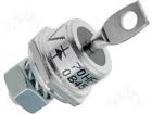
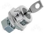
POSITIVE AND NEGATIVE STUD MOUNT DIODES
There is no such thing
as a "Positive or Negative" diode, but in car and truck alternators
there are a number of diodes to convert the alternating voltage produced
by the alternator to pulsing DC to charge the battery and operate the
lighting system.
The battery then becomes a huge storing component to smooth the pulses
to get a very smooth DC and that's why the lights don't flicker.
The alternator is actually a 3-phase generator as this will produce the
maximum output during each revolution.
The three windings are connected to 6 diodes and these diodes are
mounted on two plates that act as heatsinks.
Referring to the circuit below you can see the top 3 diodes are
connected to the purple plate (heatsink) and the 3 lower diodes to the brown plate
(heatsink).
The image above shows 3 diodes connected to a plate.
They can be ALL positive-mount stud diodes or negative-mount.
Here is a diagram to find positive-mount diodes and negative-mount
diodes:
and Negative-mount diodes at the bottom
Negative Mount Diode
Anode Body
Positive Mount Diode
Cathode Body
You will notice that both diodes have the same part number and most stud
diodes come in either "Stud Cathode" or "Stud Anode."
You need to make sure which version you are ordering BEFORE placing an
order.
Some stud diodes have different colour potting (surrounding the lead) as
shown in the following image:
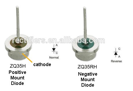
A Positive Mount Stud Diode has the cathode connected to the
STUD or "body" or screw-thread.
This is called a "normal" diode. This is not
"electronic" terminology but only refers to stud diodes for alternators.
A reverse diode sometimes has "R" added to the numbering on the
component.
The two heatsinks are insulated (isolated) from each other because one is connected to the positive of the battery and the other to the negative of the battery.
TESTING A STUD
MOUNT DIODE
THE ZENER DIODE
A zener diode should always be identified in a circuit with its voltage
next to the symbol. You can include the wattage but this can be worked
out by looking at the voltage and current flowing though the zener.
Don't use part-numbers to identify the zener voltage as the reader will
have to look-up a product-list to find the zener voltage. Circuit
diagrams should be instantly readable and instantly understandable.
The following diagram shows a zener diode producing a constant 5v6
output when the power supply ranges from 6v to more than 8v.
If the power supply is adjusted from 0v to 8v, no current flows in the
circuit when the voltage is below 5v6. As soon as the power supply
reaches 5v6, current flows through the safety resistor and the
diode. That's because the zener diode "breaks down" and current flows
through it while at the same time the voltage across the anode and
cathode leads is 5.6v
Notes:
If you want to reduce the voltage of a supply by a fixed amount, you can
use a zener diode.
This is a 6v4 supply and the current you can deliver depends on the
wattage of the zener.
Here is a mistake from a YouTube video from an instructor that does not
understand electronics:
He has put a zener across the LED, saying somehow it will work. Question Question Question Question Question Question from a reader:
5. The circuit being designed
is called a ZENER REGULATOR or ZENER SUPPLY
and the current selected from
the table above will flow AT ALL TIMES through the
resistor Rs (called the Supply Resistor
or safety resistor).
Question from a reader:
A zener question:
If you have no testing equipment, you can test a diode by
connecting a car globe to 2 leads and connecting them to a battery. The
globe will illuminate.
Now connect one of the leads to the battery via the diode. The globe
will illuminate. Reverse the diode. The globe will not illuminate.
If it illuminates in both directions the diode is faulty (shorted). If
the globe never illuminates, the diode is faulty (open).
You can do this will all the diodes on the heatsinks and compare a new
diode with the others to make sure you are fitting the correct type of
diode.
You MUST do this with every diode before you fit it as this is the only
certain way to fit the correct diode. It is so easy to make a mistake.
You can use a multimeter but a globe will not allow a mistake to be
made. You can "see" it working.
THE HEATSINK
The diodes
must be mounted on a heatsink because each diode produces a voltage
across it of about 0.7v to nearly 1v and when 10 to 20 amps is flowing
each diode can produce heat equal to 10 watts. Adding up all the heat
being lost can come to 60 watts and this is why the heatsinks get hot
and why some of the diodes fail.
Each diode must be firmly attached to the heatsink to allow the heat
produced by the diode to be passed to the heatsink.
Diodes cannot be operated "in the air" as they will get very hot and can
fail due to overheating.
The only way to test the output of each diode is with a car globe.
You can use up to 100 watts as this will test each diode under load and
identify a diode that tests ok with test equipment but fails when a high
current flows.
I am making 400v diodes and as with all batch production,
some of the diodes are good and some fail. Some fail at 50v and some at
30v and some at 12v. I don't throw them away, I just put the stripe on
the other end of the diode and call it a 12v zener diode, or a 30v
zener. That's all a 400v diode is. It is a 400v zener diode.
Before we start, a zener regulator, as discussed in the following
section, (made up of a resistor and zener diode) is a very inefficient
form of regulator to obtain a fixed output voltage. It is wasteful
because a lot of energy is lost (wasted) in the resistor and a lot of
current is lost in the zener.
Voltage regulators - called 3-terminal regulators - are much more
efficient and recent advances in the way these work has improved their
efficiency to more than 90%. And their cost is small as well as
the size. They give a more-precise output voltage over a wide
range of current capabilities and they are a more-professional way to
design a "power supply." They can supply 100mA, 1 amp and more
than 5 amps and "beat" the zener regulator "hands down."
However you need to know how a zener works and this discussion is very
comprehensive.
Zener diodes come in
voltages from 3v3 to more than 47v. You can consider them to be ordinary
diodes that have "failed." For instance a 1N4001 diode has a reverse breakdown voltage of
100v. It is a 100v
ZENER DIODE.
A 1N4004 diode has a reverse breakdown voltage of 400v. It is a
400v
ZENER DIODE.
Zener Symbol and voltage
A zener diode drops 0.7v when connected around one way and drops its
ZENER VOLTAGE when connected around the other way. Here is a diagram to
show this:
If the power supply voltage is increased, more current flows
through the safety resistor and this current also flow through the zener diode. The voltage
across the leads of the zener diode remains a constant 5v6. All
the increased voltage appears across the resistor.
If the voltage of the power supply is increased further, the current
through the safety resistor and the zener diode will increase. Both will get hotter and eventually
the zener diode will burn out.
You can produce any zener reference voltage by combining zener diodes
and ordinary diodes:
You can see the two 5v6 zener diodes in the diagram above are connected
around the opposite way to the ordinary diode. 
If the 5v6 zener is 400mW, it can pass up to 70mA. If you take more than
70mA, the zener will get too hot. The output voltage will still stay at
6v4 and nothing will go "out of regulation."
To start with a red LED drops about 1.7v.
A LED and a zener diode are exactly the same thing. They do not pass any
current until a characteristic voltage is reached.
When the voltage is reached the zener passes a lot of current and the
LED starts to glow.
This voltage is very critical and you cannot simply put this value
across the LED or zener From a battery) because it has to be very
accurate. So we add a resistor and the resistor provides the exact
current and the exact voltage.
No zener across any LED will work. The zener diode will do nothing.
Demonstrating this shows no understanding of electronics.
YouTube is filled with false information.
In the following diagram, what is the combined zener voltage?
![]()
Answer
7v A zener voltage
means a fixed and maximum voltage and when a diode is used
for its 0.7v forward voltage (such as an ordinary diode or a
zener around the wrong way), we can classify this as 0.7v
zener voltage![]()
In the following diagram, what is the combined zener voltage?
![]()
Answer
One diode is around the wrong way. The
circuit will not produce a zener reference voltage. The
output voltage will be 9v and the string of diodes will
have not effect on determining the output voltage. ![]()
In the following diagram, If the safety resistor is removed
and the 9v supply is connected directly to the two diodes
and zener, explain what will happen:
![]()
Answer
A very high current will flow through the
diodes and zener because the combined zener of the three
items is 7v. They will be damaged.![]()
Question
In the following diagram, explain what will happen:
![]()
Answer
The zener value of the three components
is 11.9v This voltage is higher than the
supply (9v) and NO CURRENT will flow in the circuit. ![]()
Here's the most absurd explanation of "Voltage Flow" in a zener
diode. Can you see the mistake?
![]()
Answer
Voltage does not "flow."
Voltage is a potential. It "exists" at each point in a
circuit. When the voltage on the cathode is higher than the
anode, the zener diode will break-down and current will flow
from the cathode to anode. When this happens the zener diode
is given a number to represent its voltage (break-down
voltage).
When the voltage on the anode is higher than the cathode,
current flows and the diode acts just like an ordinary diode
(none of the zener properties are used) and the only
property you need to remember is the current capability of
the diode. ![]()
Zener diodes can be connected in series to produce any voltage.
Simply add the zener voltages to provide the resulting output
voltage. What is the output voltage of this combination:
![]()
Answer
15v6![]()
Insert zener diode A or B to produce an output
voltage of 19.4v
![]()
Answer
Zener diode B![]()
What is the maximum supply voltage for a zener diode?
![]()
Answer
Here is the way to work out the Max
voltage for Vin:
1. You MUST include a resistor as shown in the diagram
above. The resistance of this resistor will be worked out
from the following:
2. Select a zener diode for the required output voltage. In
other words the ZENER VOLTAGE.
3. Select a 400mW diode, 1watt diode or higher wattage,
depending on the current you will be needing.
4. Work out the maximum current though the zener diode:
MAXIMUM CURRENT THROUGH ZENER
zener
voltage:
400mW
1 watt
10 watt
3v3
120mA
300mA
3 amp
5v1
75mA
200mA
2 amp
10v
40mA
100mA
1 amp
12v
30mA
80mA
800mA
15v
25mA
65mA
650mA
24v
15mA
40mA
400mA
according to the wattage of the device
This current is fed into two "loads" - the zener and
your load - called RL
When your load is not taking any current - such as
when it is "off" or removed from the circuit, ALL
the current will flow through the zener. When you
are taking the maximum current, the zener will be
taking NO CURRENT. In other words, the two items
CURRENT SHARE. They share the maximum current and
the sharing can be 0% -100% or 100% - 0%. or
any percentage in between.
6. We can now work out the maximum Vin.
7. Vin should be at least 2v higher than the zener
voltage. ANY voltage higher than the zener.
8. This voltage is called the HEAD VOLTAGE and any
voltage higher than 2v more than the zener voltage
is called WASTED VOLTAGE because it will just
produce heat in the LOAD resistor and not improve
the performance of the circuit.
9. The answer to the question:
What is the maximum supply voltage for a zener diode?
is ANY VOLTAGE !
10. We now have to work out the value of the
LOAD resistor for 400mW, 1 watt and 10 watt zener
diodes when the input voltage is 5v, 10v, 12v,
15v, 24v.
Here are the tables:
Vin = 5v
400mW zener
1 watt zener
10 watt zener
3v3 zener
15R 0.25watt
5R6 0.5watt
Vin = 10v
400mW
zener
1 watt zener
10 watt zener
3v3 zener
56R 0.8watt
22R 2watt
2R2 20watt
5v1 zener
68R 0.4watt
22R 1watt
2R2 10watt
Vin = 12v
400mW zener
1 watt zener
10 watt zener
3v3 zener
72R
1watt29R 2.6watt
2.9R 26watt
5v1 zener
92R 0.5watt
34R 1.38watt
3.4R 14watt
10v zener
50R 0.1W
20R 0.2watt
2R
2watt
Vin = 15v
400mW zener
1 watt zener
10 watt zener
3v3 zener
100R 1.4watt
39R 3.5watt
3.9R 35watt
5v1 zener
132R 0.4watt
49R 2watt
4R9 20watt
10v zener
125R 0.2watt
50R 0.5watt
5R
5watt
12v zener
100R 0.1watt
37R 0.25watt
3R7 2.5watt
The wattage
of the resistor is WASTED POWER and
Vin = 24v
400mW zener
1 watt zener
10 watt zener
3v3 zener
172R 2.5watt
69R 6.2watt
too much waste
5v1 zener
252R 1.4watt
94R 3.8watt
too much waste
10v zener
350R 0.56watt
140R 1.4watt
14R 14watt
12v zener
400R 0.36watt
150R 1watt
15R 10watt
15v zener
225R 0.25watt
138R 0.6watt
13R 6watt
some of the designs represent a lot of wasted power.
That's why a zener regulator can be a very wasteful
design.
This is called a SHUNT REGULATOR
![]()
A reader wants to convert 12v to 5v using a resistor or a
zener.
Which circuit is best?
![]()
Answer
Circuit C
Circuit A will produce 5v when say 500mA flows. But if 300mA
flows, the voltage will be higher than 5v. If 700mA flows
the output voltage will be lower than 5v.
Circuit B has the zener around the wrong way. It will
only drop about 0.7v.
Circuit C will deliver 5v if the correct value zener is used
and it has the correct wattage-rating.
![]()
The 12v supply needs to be reduced to 9v for a flashing LED.
Which way around is the zener placed: A or B?
![]()
Answer
Circuit A. The zener will drop about 3v when
the lead marked with a line is connected to the 12v supply.
The flashing LED will see about 9v and it has a microscopic
resistor inside as well as a microcontroller. A
flashing LED will accept a voltage from about 4v to 12v.
If the zener is placed around the wrong way, it will drop
about 0.5v
From a reader
Here is a mistake from an electronics forum:
The zener diode is supposed to turn the transistor off when the supply
is greater than 24v.
I don't know if the transistor is supposed to be turned ON or OFF, but
the circuit will not work.
After reading this article, you will know that a zener is "invisible"
until the voltage reaches the zener-value, but the voltage across the
base-emitter of a transistor will NEVER rise above 0.7v.
The zener will never see 24v.
The following circuit will work:
When the supply is slightly higher then 24v, the transistor will turn ON.
Another email from a reader
He asks: Why does the tiny motor
(load) go faster and slower when the supply increases and decreases?
ANSWER: The zener diode does nothing. The
voltage across the zener is equal to the base-emitter voltage of the
transistor (0.6v) and the voltage across the zener never rises to 5.6v
and thus the feature of the zener never comes into operation. The
transistor gets more current and less current as the supply rises and
fall and the motor revolves faster or slower.
To increase the voltage across the zener, you need to add a "separating
resistor" between the zener and the base of the transistor. This will
allow the zener to see a voltage higher than 5.6v when the supply is 7 -
15v and it will "break-down" and only allow 5.6v to be across it.
There will be a voltage of 5.6v minus 0.6v across the 1k resistor
AT ALL TIMES and thus the same amount of current will flow through it
and the transistor will multiply this current by about 100 times and the
load will receive this current when the load changes from 15v to 7v.
It's not absolutely constant but much better than before.
THE ZENER ANALOGY
A battery and a zener diode
behave in a very similar way and if you understand this, you will see
why it is very difficult to charge a battery from a power supply. And
you understand how a zener diode "eats-up" all the current when the
voltage rises over a certain value.
The battery is being charged from the supply rail. We know it will not
get charged when the supply rail is less than the voltage of the
battery.
As the voltage of the supply rail increases, the battery will take more
current but its voltage will not rise above 13.6v.
That's the way the zener works.
It will not allow any current to flow though it until the supply rail is
equal to the value printed on the diode. This is its breakdown voltage.
If you increase the voltage of the supply rail, the voltage on the top
of the zener diode will not increase, but the extra current that will
flow through the current limiting resistor, will flow through the
diode.
Knowing this helps you charge a battery.
If you connect the battery to a power supply and increase the voltage, a
point will come when the voltage is equal to the maximum of the battery
(13.6v) and if you continue to increase the voltage, a VERY HIGH CURRENT
WILL FLOW and maybe damage your power supply.
The technical answer to this is: There is no current limiting resistor.
THE LED - How it is like a zener diode !
Now we are going to talk about something AMAZING.
It's a LED - LIGHT EMITTING DIODE. It is just like the diodes we
have described above and just like the ZENER DIODES we have talked about
above.
Yes, that's right a LED is just like a diode and functions just like a
diode but it just like a diode with a window so you can see the current
flowing through it.
This is a wonderful advantage. Now you can see when a diode or zener
diode is WORKING !
But a LED has two slight differences. It is not like a 400v diode but
just a 5v diode. A LED can only withstand about 5v to 7v in the reverse
direction before it is damaged. This means you can use a LED on any
circuit up to about 5v.
And the other thing is a LED can only pass about 20mA, whereas a 1N4004
diode will pass about 1,000mA.
And a LED is just like a zener, but instead of a zener voltage of say
12v, a LED had a zener voltage of 1.7v for red and about 3.6v for white.
Now you can use all your knowledge about diodes and zeners and reference
it to a LED in a circuit where less than 20mA is flowing , the voltage
is less than 5v and the zener reference is 1.7v to 3.6v or any multiple
or addition of these voltages.
This concept is NEW. It has never been explained or covered in any text
book in the way we are explaining it.
No-one has thought to show the similarities and that's why you get so
many questions on electronics forums about the operation of a LED and
why you need a current-limiting resistor.
THE TRANSISTOR AS A ZENER DIODE
A transistor exhibits "ZENER CHARACTERISTICS" when placed in
a circuit as shown in the following diagram:
The base-emitter junction is "reverse biased." In other words, it has
voltage across it that is opposite to the normal way the transistor is
used.
The junction cannot withstand a very high voltage in this direction and
it BREAKS-DOWN.
In other words it starts to allow current to flow through the junction
and a voltage is created across this junction. The resistor is provided
to prevent a high current to flow through the junction and to allow the
junction to break down and create the natural value across the two
leads.
This is called ZENER BREAKDOWN.
The voltage will depend on the type of transistor and can be anywhere
from 6v to 8v. For a particular type of transistor it will be quite
stable (fixed) and you can allow say about 10mA to flow through the
junction. The transistor will not be damaged.
THE SHUNT REGULATOR
We will now
combine all the facts we have learnt from above to produce a circuit
called a SHUNT REGULATOR.
A Shunt Regulator takes a high voltage (containing ripple) and
produces a lower FIXED voltage with very little ripple.
We have learnt that:
1. A BRIDGE converts AC to DC (pulsating DC. DC with ripple).
2. An electrolytic smoothes the pulsating DC and reduces the ripple.
A shunt regulator FURTHER REDUCES THE RIPPLE and produces A FIXED
VOLTAGE.
A SHUNT REGULATOR consists of two components: A resistor (called
the current limiting resistor) and a zener diode.
Here's how the SHUNT REGULATOR works.
Firstly, the zener diode and resistor work just like a dam with an
overflow pipe
at the top. If the water level in the dam does not reach the pipe, NO
water overflows. When the water reaches the pipe, it overflows
through the zener pipe. If the water level rises further, more water
flows through the zener.
The height of the water is never above the small overflow pipe.
The small overflow pipe is connected to the globe and the brightness of the
globe is constant because the voltage on the cathode of the zener is
fixed (by the action of the zener diode).
It does not matter how much ripple is present in the incoming waveform,
the value of the resistor is chosen to eliminate ALL THE RIPPLE.
The mathematics to work out the value of the resistor is very complex as
it involves the resistance of the resistor, its wattage and the wattage
of zener.
This is covered in the article: The
Power Supply and also above with a set of tables.
The height of the small overflow pipe can be taken to a LOAD such as GLOBE.
The load can only be a SMALL LOAD. In other words, it can only require a
small current, such as a small torch globe.
If the load takes ALL THE CURRENT (coming from the resistor), the
zener will get NO CURRENT and it will DROP OUT OF REGULATION.
In other words, the voltage on the cathode of the zener will drop.
This is exactly like putting a pump on the small overflow pipe and
sucking all the water from the zener:
Question
Why use a SHUNT REGULATOR?
![]()
Answer
A SHUNT REGULATOR is a
very cheap and simple way to produce a clean output voltage
(with very little ripple) from a higher voltage that has
ripple.
You must design the circuit so that the output voltage is a
few volts below the lowest dip in the voltage being
supplied. The Shunt Regulator circuit is not MAGIC. It
simply deliver the voltage below the ripple that has NO
RIPPLE !!
![]()
We can now add the bridge and smoothing
electrolytic:
Waveform
Waveform B represents the waveform as it emerges from the bridge. (The electrolytic is not connected to detect this waveform.)
Waveform C shows the effect of the electrolytic. It stores energy from the peaks and delivers the energy when the waveform drops. The result is DC with a small amount of ripple.
Waveform D is very smooth DC at a voltage determined by the voltage of the zener.
Question
In the diagram above, describe the shape of the output voltage D if the electrolytic is removed
| Answer The pulsing DC will produce a waveform on the cathode of the zener as shown in the following diagram:  This will not matter if the load is a globe but if the load is an amplifier, the power supply will produce HUM. |
ZENER QUESTION
Here is a circuit from the web and an answer from the
instructor:
The description is incorrect. Can you see the mistakes????
This circuit is called a CURRENT DEFINED CIRCUIT. In other words,
you describe its action when a change in CURRENT occurs.
If the load takes more current, it robs this current from the zener.
When the circuit is working correctly, the ZENER and LOAD are sharing
current and the current through the resistor
You can see how many mistakes are in the answer above:
The current through the resistor DOES NOT CHANGE, the voltage across the resistor DOES NOT CHANGE.
This means the voltage across ALL THE COMPONENTS does not change and it is pointless describing the circuit in terms of voltage.
Now you can see how the electronics engineer that described this circuits does not understand how to describe its operation.
He started with the wrong premise by saying: If the voltage across the load tries to fall.
He should have said: . . .due to an increase in current required by the load.
He would then be able to describe the circuit using only CURRENT changes.
MORE ZENER DISCUSSION
I have never used a zener diode as a regulator because it is
very inefficient and very wasteful and can only deliver about 50mA.
But it can be used as a reference voltage, plus other very clever
applications.
Here’s the reason it is very inefficient as a regulator.
A certain maximum current is set (for the number of milliamps you
require for the load you will be connecting to the circuit).
You can take up to this amount of current, providing you leave 3 to 5mA
through the zener to keep it in “break-down.”
This means the same amount of current will be flowing all the time and
if you are not taking it, the current will flow through the zener and be
wasted.
If the load is removed, the Zener will get very hot and you must make
sure the zener will handle the temperature.
In other words you can “rob” the zener up to a point of about 3mA.
This is always the case and when the zener is used as a reference
voltage, the current through the zener will be very small, because you
don’t need much current to keep the zener in “break-down.” Allow 1-2mA.
What happens if you take all the zener current, and a little bit more?
The accurate voltage you were getting will reduce slightly. This may or
may not be important, and it is called “dropping out of regulation.”
The zener regulator actually reduces and removes ripple. Providing the
zener remains conducting (or passing, or dropping, or wasting) current,
it will also remove ripple.
I have used a zener, resistor and LED in series to allow the LED to
illuminate when the voltage on a capacitor has reached a particular
voltage.
The characteristic voltage across coloured LEDs can be considered a
zener voltage because it has a certain value and it can be treated like
a zener diode with a “glow feature.”
When ever a voltage appears across a zener diode, and a current flows
through it, the zener will get hot. You must solder a zener to big lands
and thick tracks, as these are the only things that will dissipate the
heat and prevent the zener from being damaged.
The 400mW, 1w, 5w etc (wattage rating) only applies when the zener is
soldered in place.
Zeners will get much hotter for the same current as an ordinary diode
because the voltage across it is much larger. For example, a 12v diode
passing 1A will get 20 times hotter than a power diode.
To be on the safe side, you should always be able to hold your finger on
the zener.
THE SERIES
REGULATOR
The SERIES REGULATOR can be identified by the fact that the
zener diode does not pass all the current when the load is
removed.
This type of circuit is much less wasteful than the Shunt
Regulator.
You can also see the current (actually the voltage and the
current) passes through the controlling device (the
transistor) and then the load, just like two components
in SERIES.
In fact, we have a shunt situation with the zener and 1k
resistor as the voltage across the 1k is 8v and this causes
8mA to flow through the 1k and thus the zener has 8mA
flowing through it.
If the transistor has a gain of 50, it will allow up to 8 x 50 = 400mA
to flow through the collector-emitter circuit.
But if you try to take more than 400mA (by connecting a load with a very
low resistance) the whole circuit will DROP OUT OF REGULATION.
This means the output voltage will drop below 15.4v.
Let's see how this happens.
When the load takes 50mA, the collector-emitter leads of the transistor
deliver this current and the base takes 1mA from the zener diode. This
means the zener sees 7mA.
When the load takes 400mA, the base takes 8mA and the zener diode gets
NO current.
Up to this point, the circuit works perfectly.
But if you take 450mA, the base requires 9mA and when 9mA flows through
the 1k resistor, the voltage across the resistor is 9v.
This means the base is 24v - 9v = 15v and this voltage is lower than the
breakdown voltage of the zener.
The zener only has the capability of preventing the voltage rising
above 16v, it does not have any control when the voltage delivered
to it is less than 16v.
The output voltage is now 14.4v and the circuit is said to have DROPPED
OUT OF REGULATION.
Here is an unusual use for a zener diode in the bridge of a power supply:
![]()
This is a very special type of power supply called a TRANSFORMERLESS POWER SUPPLY and it shows the effect of putting a diode in the bridge that has a very low breakdown voltage. Normally the 4 diodes will have a peak reverse voltage (breakdown voltage) of 200v or 400v and this effect will not be noticed. But when two 18v zeners are included to demonstrate the effect of "breakdown voltage" the output of the supply is 18v minus 0.7v across the lower diode.
TAKE NOTE OF THE FOLLOWING
A zener diode will work in the transformerless power supply shown above but now we add it to a 24v power supply from a transformer. What will happen?
The 24v winding is capable of delivering a high current and as the voltage rises it reaches 18v and this is the rating of zener diode. The rating means the voltage across the zener cannot rise higher than 18v as it “breaks down” at this voltage and effectively become like a shock absorber that you try and pull past its expansion. The zener diode will not allow a higher voltage to appear across it and we have a condition just like a short circuit. Instead of the short circuit being at 0v when the the two leads are connected together, (and a high current flows), the ”short” occurs at 18v and when the voltage rises higher, the higher voltage causes a high current to flow and this current gets higher and higher to the maximum produced by the transformer. This current will flow through the zener and it will blow up.
What happens if the zener is placed in the other leg of the bridge?
In this position, the zener does not produce a voltage on its output
until the input voltage is above 18v. This means only 6v from the
supply will appear on the output and a further 0.7v will disappear
across the diode marked "A." You can see the zener diode
has been placed in the circuit, just like the zener in the following
circuit, but it is higher with respect to the voltages.
The diode will get very hot, very quickly and possibly be destroyed.
What happens if the zener is fitted around the other way?
In the circuit above, the zener characteristics are not produced by the
zener. This means the voltage is effectively a REVERSE VOLTAGE as far as
the zener is concerned and it will act like a normal 400v diode that has
failed at the 18v "testing voltage."
The power supply will work perfectly because there is no reverse voltage
(such as with AC rectification).
A ZENER IN A POWER SUPPLY
To make this discussion simple we will assume the output of the supply
is
15v and the zener is 5v1. What is the output voltage?

The zener will not conduct until the voltage is above 5.1 volts.
This means you lose the first 5.1volts.
The output voltage will be 9.9 volts.
However the zener diode may get very hot. If you are drawing one amp
from the 9.9v supply, the wattage lost by the zener will be 5.1 watts
for half a cycle and zero loss for the second half cycle = about
2.5watts per cycle. Normally the wattage lost will be 0.7 x 1 amp
and this is divided by 2 to get the full cycle losses = 0.35 watts, as
the voltage drop across a normal diode is 0.7v to 0.9v.
I want to reduce the "source-to-gate voltage" to 3v3. Which way around do I place a zener diode: A or B ?

Ans: A
As the voltage across the 2k2 increases, it will not rise above 3v3 because at
3v3 the zener diode "breaks down" and the additional voltage you are
supplying comes with additional current and this current flows through the zener
also through the 4k7 resistor and produces and larger voltage across the
resistor and that's why the zener does not see a higher voltage.
You need to have, what we call a "current limiting resistor," in series with the
zener for the concept to work. That's what the 4k7 does. If it is a lower value,
it simply means the zener will be required to pass a higher current and the
current through the resistor will be higher.
A zener diode is just like an ordinary diode with a very small reverse
break-down voltage. A normal diode has a reverse voltage of 100v, 200v,
400v or 1,000v.
A zener diode has a reverse voltage of 3v3 or 5v1 or 12v or 18v.
You can think of a zener diode as a "failed" diode. Instead of being a 100v
diode, it fails at 5v1 or any other design-value.
This is due to the "doping" of the crystalline structure of the junction and the
voltage can be accurately produced.
A zener diode is actually an ordinary diode connected around the opposite way as
we are using the very small "break-down" voltage as the useful characteristic.
When you understand this feature you
can use zeners in many different applications.
A ZENER QUESTION
A 3v3 zener is supplied with a current of 100mA.
A: If your load requires 50mA, what is the voltage across the zener?
B: If your load requires 100mA, what is the voltage across the zener?
C: If your load requires 150mA, what is the voltage across the zener?
Ans A: The voltage across the zener will be 3v3. The zener will get
50mA.
Ans B: The voltage across the zener will be 3v3, but the zener will
get no current.
Ans C: The voltage across the zener will be less than 3v3. The
zener will come out of "regulation" and the output voltage will be determined by
the voltage divider made up of the resistance of the load and the resistance of
the current limiting resistor, supplying current to the zener.
CURRENT SHARING
The current though the zener and the current though the small globe is
called CURRENT SHARING. They share the current coming from the
resistor. The resistor is called a FEED RESISTOR or FEEDER
RESISTOR or CURRENT LIMITING RESISTOR or CURRENT
DETERMINING RESISTOR. It is NOT a LOAD RESISTOR.
It is designed to deliver CURRENT to the zener and globe. The
globe is the LOAD.
A shunt regulator consisting of a zener (and resistor) is designed to
deliver a small current. If a large current is required, a
transistor is added to the circuit, called a PASS TRANSISTOR or a number
of different circuits can be used.
We will now cover CURRENT SHARING:
Diagram A above shows the correct CURRENT SHARING between the
zener and globe. The zener should only be taking a few milliamps as this
current is wasted and the zener is only required to provide a fixed
voltage.
However if the load is removed, all the current taken by the load will
not flow through the zener and that's why the zener must be capable of
dissipating this wattage.
Diagram B shows what will happen if the supply voltage increases.
The CURRENT through the feed resistor
will increase. This is similar to more water flowing though the pipe
containing the feed resistor and the extra water will flow though the
zener.
Here is the reason:
The voltage on the cathode of the zener is fixed (the voltage
delivered to the globe is fixed). This means the current taken by the
globe will remain constant. Thus any extra current can only flow though
the zener.
We will now change the globe for a motor:
If the supply voltage remains constant and the motor takes more current,
it robs the current from the zener. This shown in diagram B
above. If the motor takes even more
current, it will take ALL THE CURRENT from the zener. This shown
in diagram C above.
Up to now the voltage across the motor is constant. But if the motor
wants more current, the SHUNT REGULATOR will drop out of
regulation and the voltage across the motor will DROP.
The motor may or may not get more energy from the supply, but we
will not go into this condition because the SHUNT REGULATOR has ceased
to perform.
The SHUNT REGULATOR is called a SHUNT REGULATOR because the zener
is connected directly across the voltage being delivered to the LOAD and
it "shunts" (takes away) ALL the current being delivered by the resistor
(if the load is removed). When a LOAD is connected, it takes current
from the zener and it can do this until almost all the current is taken.
You must leave a small current through the zener to keep the circuit in
REGULATION.
The SHUNT REGULATOR is a very wasteful design as current is
flowing ALL THE TIME. If the load is not using the current, it is being
wasted through the zener.
Take the case of "power diodes."
Suppose you have a 1-amp power supply and intend to use four 1N4004 diodes in a bridge.
We have already mentioned that this type of diode has a voltage drop of 0.7v when the current is about 500mA but increases to 1.1v when the current is 1 amp.
By using an extra set of four diodes in parallel with the first set, the current through each diode will be shared. The current may not be shared equally, but it will be much less than 1amp (through each diode) and the overall wattage-loss will be less and this will be shared between two diodes. Overall, a very good outcome.
ACTUAL ZENER CIRCUIT
Here is a circuit using a 15v zener diode.
Here's how to look at this circuit:
The input voltage is 20v.
Remove the three "rectangles."
The zener diode will create a rail voltage of 15v and all the current
from the 20v supply will pass through the zener.
This current can be worked out by looking at the 220R resistor. It has 5v
across it and the current flowing will be: V =
I
x R 5 =
I
x 220 = 5/220 = 22mA
The regulator requires a small current to drive the transistors inside
the chip. Say this is 2mA.
The Microcontroller requires a small current to operate. Say this
is 6mA.
The gate driver uses 1mA.
The remaining 13mA flows through the zener.
Suppose the microcontroller turns ON and output line and takes an extra
13mA.
This means NO CURRENT will flow through the zener and it will DROP OUT
OF REGULATION.
The rail voltage will remain at 15v but the zener will have no part in
this circuit (at the moment).
If the micro wants say 2 more milliamp (to drive another output device)
the 15v rail will drop slightly.
The 5v rail will remain at exactly 5v and the 15v rail will drop a small
amount.
This circuit is called CURRENT SHARING.
The 3 devices in the rectangles SHARE the current with the zener. There
is 22mA to share between the 4 items.
You can also say the 3 devices TAKE current from the zener or ROB
(steal) current from the zener and when all the 22mA is STOLEN, the 15v
rail drops in voltage and we have lost what is called ZENER
REGULATION.
Zener Diode Question
In the following diagram, describe a fault:
![]()
Answer
The circuit does not have a safety
resistor
What voltage does the red LED detect?
Answer
The circuit detects a voltage
between 24.9v and 25.1v
Any voltage above this may damage the red LED.
Question
In the following diagram, at what voltage will the red LED start
to turn ON:
![]()
Answer
The LED will start to turn on at about
9.1v + 9.1v + 5.1v +1.7v = 25v
When the LED starts to turn ON, the current will be very small and the
voltage across the 1k resistor will be almost zero.
Question
In the diagram above, if the LED can pass a maximum of 20mA, what is
the maximum voltage of the supply?
Answer
When 20mA flows, the voltage across the 1k resistor will be 0.02 x
1,000 = 20v.
This means the voltage can rise to 25v + 20v = 45v.
Question
In the following diagram, what is the zener voltage across the
combination:
![]()
Answer
One of the top 9v1 is around the wrong way and it will drop 0.7v.
The bottom 5v1 and 9v1 are in parallel and the lowest voltage zener will
determine the voltage across the pair. The answer is 0.7v + 9v1 +
5v1 = 14.9v
Question
If the supply is very weak and can only supply 20mA, will the LED be
damaged with 30v?
Answer
The voltage across the circuit above will never rise higher than 25.0v
and the 30v supply will be pulled down to 25v. Approx 20mA will flow.
Question
What will happen in the circuit above if one of the 9v1 zeners is
reversed?
Answer
The 9v1 zener will become a 0.7v normal
diode.
The LED will start to come on when
5v1 + 9v1 + 0.7v + 1.7v is applied
Question
What will happen in the circuit above if the 5v1 is replaced with
a 1k resistor.
Answer
The LED will start to come ON when the voltage reaches
9v1 + 9v1 + 1.7v. And the 1k resistor will start to limit the current
and the voltage can rise to 19.9v and up to about 30v without damage as the
1k will drop the extra voltage across it and the current will rise in
the circuit. The current can be allowed to rise to about 20mA.
Every ONE VOLT across the resistor will allow 1mA to flow in the
circuit.
Question
What will happen if the LED is reversed?
Answer
It will not illuminate
Question
What will happen if all the parts are fitted the right way around
but in the wrong locations on a Printed Circuit Board?
Answer
The circuit will work perfectly.
Question
What will happen if all the parts are fitted the right way around but in
the wrong locations on a Printed Circuit Board?
Answer
The zeners will each drop 0.7v and the LED will see more than 20v for a
25v supply and this voltage will be in the wrong direction. A LED will
be damaged if the reverse voltage is above about 7v.
Question
For the circuit above, what will happen if the two 9v1 zeners are placed
in parallel and not series?
Answer
The circuit will drop 5v1 + 9v1 and the two 9v1 zeners will each share
the current equally. If each 9v1 zener is 400mW, the combination will
become a 9v1 800mw zener.
Question
If 50mA is flowing through the following three zeners in series: 5v1 +
9v1. + 12v, which zener will get the hottest?
Answer
12v
Wattage is the voltage (in volts) multiplied by the current in amps.
(Milliwatts is the voltage in millivolts multiplied by the current in
milliamps. )
The 12v zener will dissipate 12 x .05 = 0.6Watts = 600milliwatts
You will need a 1watt zener. Or you can put two 12v zeners in parallel.
Question
If you put two 12v zeners in parallel but the second zener is around the
wrong way, what will happen?
Answer
The voltage drop will be 0.7v, no matter which way you connect the
supply.
Question
What will happen if you connect 12v across the combination?
Answer
One of them will burst into flames and the other will get very hot.
You cannot put 12v across a 12v zener because as soon as the voltage
rises above 12v it allows a very high current to flow.
Any voltage applied to a zener must include a SAFETY RESISTOR to limit
the current.
You do not know how much current is going to flow at any stage of your
experiment and a safety resistor of 1k will get hot and let you know
what is happening.
If you put 12v across a 12v zener, nothing will happen. If you put 12.1v
across the zener, a small current will flow and 12.1v will appear across
the zener.
If you put 12.2v across the zener, 12.2v will appear across the zener
and a large current will flow. If you put 12.3v across the zener, it
will get very hot and be destroyed.
GATING - how a diode can
be used as a GATEE
The technical way to describe a diode is:
A diode only allows current to pass in one direction.
This also means a diode only allows voltage to appear on the cathode
when the voltage on the anode is above 0.7v.
We can use this feature to INHIBIT (stop) an oscillator and also produce
circuits where two or more inputs determine the output of a circuit.
This is called GATING.
We will cover two features, Gating An Oscillator and creating
Diode Gates
GATING AN
OSCILLATOR
We are not
interested in how the oscillator works. We want to STOP or INHIBIT the
oscillator via an input signal.
The simplest type of circuit to "control" or "gate" is a DIGITAL
OSCILLATOR. This is an oscillator made up of a BUILDING BLOCK contained
in an INTEGRATED CIRCUIT.
The Building Block is also called a GATE and we have two terms called
"GATE" in this discussion.
The Building Block may be an AND gate, OR gate,
Inverter or Schmitt Trigger.
The other "gate" in this discussion is the action of turning ON or
turning-OFF the oscillator.
The "gate" is the diode on the CONTROL LINE and it is taken HIGH
or LOW to control the oscillator.
In the following circuit, the INTEGRATED CIRCUIT (IC) contains 6 Schmitt
Triggers and each Schmitt Trigger is called a BUILDING BLOCK or
Schmitt Gate. It oscillates due to the resistor R and
capacitor C.
The voltage on the capacitor "C" rises to 2/3 rail voltage (via resistor
"R") and this is detected by the IC to make the output LOW. The
capacitor now discharges to 1/3 rail voltage via resistor R and the IC detects
a LOW to
make the output HIGH. An animation of the circuit is available from
Talking Electronics on the CD of the whole site.
Subscribe to the CD for $10.00.
A gating diode can be placed on the "control line" to control (inhibit)
the oscillator:
When the gating diode is taken HIGH, the oscillator is "jammed" (inhibited - frozen):

The oscillator is INHIBITED
In the diagram above, the voltage through the gating diode will keep the capacitor charged and prevent the IC changing state. The oscillator is INHIBITED.
In the diagram above, the gating diode does NOT inhibit the oscillator.
The oscillator produces a square-wave output.
If the gating diode is reversed, a HIGH on the cathode will NOT inhibit the
oscillator:
A gating diode connected to 0v, as shown below, will inhibit the oscillator:
The gating diode will only allow a voltage of 0.7v to appear across its leads. This voltage is too low for the input of the IC and thus the circuit will not change state. The oscillator is INHIBITED.
The gating diode is normally connected to the output of a controlling circuit, as shown below:
The first oscillator controls the second oscillator via the gating
diode.
The operation of the Schmitt Trigger oscillators is fully covered in the
Interactive section of Talking Electronics website and on the CD of the
whole site.
Subscribe to the CD for $10.00.
We are only covering the operation of a diode in this discussion.
It is important to understand the effect of a gating diode on the operation of an oscillator (as shown in the diagrams above).
Question
Is the oscillator inhibited (stopped - halted - frozen) when the anode of the gating diode is HIGH?

| Answer Yes. The voltage via the diode will keep the capacitor charged and the oscillator will be frozen with the output low. |
Question
Is the oscillator inhibited when the cathode of the gating
diode is HIGH?
![]()
Answer
No. The voltage on the cathode will not
pass through the diode and the operation of the oscillator
will not be affected. ![]()
Question
Is the oscillator inhibited when the cathode of the gating
diode is LOW?
![]()
Answer
Yes. The 0v
on the cathode will put a maximum of 0.6v on the anode and
this will keep the capacitor discharged and the oscillator
will be frozen with the output high. ![]()
Question
Is the oscillator inhibited when the anode of the gating
diode is LOW?
![]()
Answer
No. 0v on
the anode will not pass through the diode. The diode will
allow a voltage of at least 100v to appear on the cathode
and thus the operation of the oscillator will not be
affected. ![]()
DIODE GATES
Diodes can be connected so that two or more CONTROL LINES determine the
state of an output.
This is called GATING and more-specifically DIODE GATING.
The two diode gates are: AND GATE OR GATE.
An AND GATE is HIGH when both inputs are HIGH.
An OR GATE is HIGH when either input is HIGH.
Notes:
1. For a Diode Gate, we are not concerned with the 0.6v to 0.7v drop
across the diode.
2. A Diode Gate is classified as DIGITAL GATE. In other
words, the output is either HIGH or LOW.
3. When it is HIGH, the output is as close to the rail voltage of
the system as possible. This voltage is normally 5v, but it can be 3v3
for a 3v3 system or 12v of other systems.
4. When it is LOW, the output is as close to 0v as possible.
THE DIODE
The voltage and current is passed to the output by the incoming signal and a pull-up resistor is not needed. A pull-down resistor will prevent the output "floating."
The output will go HIGH when line A OR line B is HIGH (and also when BOTH inputs are HIGH).
A voltage-drop of 0.6v is lost across the diode but this will not affect any circuit using this gate.
For the diode AND gate, BOTH input A AND input B must be HIGH for the output to be HIGH.
The diode AND gate works in a slightly different way to the diode OR gate.
The pull-up resistor delivers the output voltage and current.
The input lines ALLOW the output voltage to rise when BOTH inputs are HIGH. The output current of the AND gate is determined by the value of resistor R. When the output is low, this current is termed BLEED CURRENT and flows through the diode(s) to the 0v rail. This current is "waste" current and must be kept to a minimum for good design.
NAND and NOR gates cannot be produced with diodes and resistors as these gates involve INVERSION and a diode cannot provide inversion. A transistor or IC is needed to provide inversion.
The OR and AND gates above are called DIGITAL GATES because the output is HIGH or LOW. This condition is created because the input lines are DIGITAL LINES - they are either HIGH or LOW.
Question
Is the following circuit an AND gate or OR
gate:
![]()
Answer
The two diodes are connected around the
wrong way. The circuit is not and AND gate or OR
gate. ![]()
Question
Is the following circuit an AND gate or OR
gate:
![]()
Answer
The gate is an
OR gate. ![]()
THE TRANSISTOR
A transistor can be considered to have a diode
between between the base and emitter leads because these two
leads behave just like a diode. We have shown an NPN transistor
in the diagram below, but the same applies to a PNP transistor.
This fact is important to know when analysing circuits such as this one:
The circuit will not start to turn ON until the voltage on
the base of the NPN transistor is 0.6v.
This voltage is provided by your finger on the Touch Pads and
the top 100k resistor.
At the beginning of this article we mentioned the fact that the
voltage across a diode can be increased from 0v to 0.55v and
nothing flows through the diode.
This is exactly the same effect with the base of a transistor.
The transistor does not conduct until the voltage on the base
reaches 0.6v and if the voltage is increased, above 0.55v,
current will start to flow "through the diode" - "through the
base lead to the emitter."
Although a diode and base-emitter junction of a transistor are
NOT the same thing - we can use this simple explanation to
understand how the two components work.
In the case of a diode, as the voltage is increased over 0.6v,
more current flows through the diode. In the case of the base of
a transistor, as the voltage is increased over 0.6v, the
transistor turns ON more and more current flows through the
collector-emitter terminals.
(The voltage 0.6v can range from 0.6v to 0.9v, depending on the
type of diode and the current flowing.)
The whole point to understand is this: NO current flows until
the voltage across the diode is 0.55v and as the voltage is
increased, more current will flow (in the case of a
transistor).
In the case of a diode, you can add this interpretation:
As the circuit requires more current, the additional current
will flow though the diode and create a higher voltage-drop
across it.
BREAKDOWN
No semiconductor device can withstand a very high voltage and we will look at what happens.
This is a very important topic because we use this breakdown feature in some circuits and other times we need to know how to prevent breakdown.
If a transistors sees a high voltage such as a spike (and the voltage has a reasonable amount of current) the transistor will be instantly damaged.
If the current is low, the transistor can be repeatedly operated with the feature.
Here's what will happen to a diode, zener diode and transistor:
The voltage across a signal diode or power diode or zener diode
will be equal to rail voltage when the voltage is below the
breakdown or Avalanche voltage of the diode. In other words, no
current will flow through the safety resistor and no voltage
will be dropped across this resistor.
However, when the voltage reaches the Peak Inverse Voltage for a
Diode, or the avalanche voltage for a zener, the device will
breakdown and cause current to flow through the device so that
the voltage on the cathode will not rise any further. As you
increase the voltage, the current through the device will
increase but the voltage across it will not change. The device
will get hotter and hotter until it fails with overheating.
The same will occur with a transistor. When the voltage on the collector
reaches the maximum for the transistor, it will breakdown and
the voltage across the collector-emitter will remain at this
voltage.
Fig
D
shows how a diode (or zener diode) can be used to pass voltages
that are higher than the breakdown voltage of the device.
Nothing flows though the device until the breakdown voltage is
reached and then the exact-same-waveform flows though the
device.
Note: When the three devices are connected in the reverse
direction the diode and zener will drop (breakdown) at 0.6v and
the transistor will breakdown at a very low voltage.
WHY DOES A DIODE FAIL?
The PIV on the diode is 31v
Here we have a
simple circuit for charging a battery. The diode is 4 amp with
a PIV rating of 30v. The PIV rating is the voltage the diode is
capable of withstanding in the opposite direction. This is just
an example of what will happen.
When the output of the transformer is positive on the top, the
voltage across the diode is about 0.6v (or as high as 1v when 4
amps flows) and the wattage dissipated by the diode is about 4
watts.
When the voltage reverses direction, the top output of the
transformer becomes NEGATIVE and it just like the winding
"flips-over" to produce the second circuit.
The diode sees a negative voltage on one end and a positive
voltage on the other lead.
This means a total of 15 and 16 = 31 volts is across the diode.
When the voltage reaches 30v, this is the PIV voltage for the
diode (this can also be called the zener voltage) and it BREAKS
DOWN at 30v so that any voltage higher than 30v allows current
to flow through the diode FROM THE BATTERY to the TRANSFORMER.
This current will be very large because the battery is capable
of delivering a high current and the transformer winding will be
a thick wire and if it is capable of delivering 4 amps when
charging the battery, it will accept a higher current in this
"break-down" condition.
The current will be as high as 5 to 10 amps or more.
Suppose 5 amps flows.
The wattage dissipated by the diode will be 5 x 30 = 150 watts.
Obviously the diode will be destroyed very quickly.
That's why a diode in a 12v battery-charger needs to have a PIV
rating higher than 30v.
HEATSINKING
You might not think a power diode needs to be HEATSINKED because
there are no heat-fins on a diode. But the leads and pads on the
PC board form a very important part of getting rid of the heat
generated.
The author has seen examples of one pad being smaller than the
other and the lead heated up the solder to produce a dry joint.
In another case, the small pads resulted in the diode
overheating and "shorting;" and other diode "going open."
So, the quality of the heatsink is VERY IMPORTANT.
If you cannot hold your finger on a diode for 10 seconds, it is
TOO HOT.
Adding extra-wide pads and tracks on the underside of the board
is a very good idea.
Power diodes are very robust, however it is good engineering to
add extra track-work to prevent over-heating.
PROBLEM FROM A READER:
I am working on an automotive air-conditioner system that
keeps blowing fuses.
I disconnected the compressor and the fuse still blows. I figure
I have either a short to ground on the wire from the relay to
compressor....or maybe there is something going on with the
diode.
Here is the circuit:
Circuits with lots of plugs and
numbers and figures are very hard to follow.
Here is a simplified circuit to show the diode is connected
between the positive line into the compressor clutch and ground:
If the diode is "shorted" it
will put a low resistance on the line into the clutch and "blow
the fuse." This is the first component to replace, as a
short-circuit in the wiring is a rare problem.
Remove the diode and check the resistance in both directions
with a multimeter set to LOW OHMs. Alternatively, connect the
diode to the positive lead of a 12v globe and then a 12v battery. Now turn
the diode around the other way. The globe should NOT illuminate.
A diode can fail due to vibration, heat, stress on the leads, or
voltage spikes. Although these faults are rare, you must
remember these are all possibilities as well as the diode going
intermittent and failing when a high current is passing through
it.
You must remember also, a diode is made of materials that
break-apart very easily. The only thing that keeps them together
is the body of the diode. If the body of the diode expands, the
junction separates.
DIODE DROP
There are a few areas in a circuit where the
voltage is very critical.
One of the areas is the voltage across a diode. It is called a
DIODE DROP and it is referred to a CHARACTERISTIC VOLTAGE
or CHARACTERISTIC VOLTAGE DROP.
You have no control over it and you cannot change it.
But it does change very slightly according to the current.
The voltage across a diode might be 0.3v, 0.65v, 0.7v, 1.7v,
2.3v or 3.2v.
It depends if the “diode” Is a Schottky Diode, an “ordinary
diode,” a power diode, the base-emitter junction of a transistor
or a red, green, orange, blue or white LED.
You cannot change or control this characteristic and you cannot
deliver the exact voltage.
Too much voltage and the diode will be destroyed.
And all these conditions depend on where the diode is used.
However there is one component you can add to deliver the exact
voltage and it is a RESISTOR.
The resistor is called a CURRENT LIMITING RESISTOR and it
allows you to deliver the exact voltage without damaging the
diode.
However you have to know what to do.
In the following, the voltage from the supply can be any voltage
above 0.3v and the voltage across the diode will remain constant
up to a supply voltage of 12v or more. All that will happen is
the current through the diode will increase.
That's because the voltage across the resistor increases and
thus the current through the resistor increases. This current
also flows through the diode.
But the circuit is not trying the increase the voltage across
the diode. A diode does not like, and does now allow the voltage
across it to be increased. If you try to do this, a huge current
will flow through the diode and it will "blow up."
You must have a resistor to protect it.
All diodes are rated with a maximum CURRENT. It might be 50mA,
100mA, 500mA,1amp, 2amp or more.
You can increase the supply voltage until this current is
reached. The resistor will protect the diode.

The circuit above shows how the diode is protected.
In place of a power diode, you can use a LED. A LED is a diode
that produces light.

The resistor prevents the LED being destroyed. As you increase
the supply voltage, the LED increases in brightness. You have to
know when to stop.
This is how you conduct the experiment:
Start with a supply of 6v to 12v.
Start with 1k resistor.
Reduce the resistance to 470R and this will be the maximum
brightness you will get for a long, LED life and economical
current.
Every diode has a limit to the amount of current it will “pass.”
It depends on the size of the junction and how hot it gets.
LEDs are very economical and modern LEDs will glow brightly on
1mA to 20mA.
They are called "bright" and "super-bright."
And they have become much more efficient.
THE ZENER DIODE
Here is an interesting demonstration to help you understand the
ZENER DIODE.
A LED is a zener diode. It is a diode and also a zener diode that
shows how much current is flowing. The current can only range
from 1mA to 30mA. Above this, the LED will "burn-out."
Here is the circuit:

This is a TEST CIRCUIT. It has no safety resistor because it
will only be supplying 1mA to 30mA to a LOAD. And you must keep
the current to this value.
The LED will indicate how much current is flowing and you will
lose 1.7v if you use a red LED. Other colours will drop a
different voltage.

If you connect two LEDs, the total voltage drop will be 3.4v

You can replace the two LEDs with a single 3.4v (or 3v3) zener
diode.

Now you know what a zener diode does.
Technically speaking, it is simply a FAILED POWER DIODE.
Power diodes are available with voltage ratings of 100v, 400v
and 1,000v at 1amp.
You can also get them with 50v rating. This is actually a 50v
Zener diode.
This means a 50v power diode is only good for an AC circuit with a
voltage below 50v as a 100v circuit will have a voltage that is
positive 100v and then negative 100v.
The 50v diode will only allow the circuit to reverse by 50v as
it only “stops” a voltage up to 50v in the reverse direction.
It will work perfectly in any circuit up to about 40v.
The voltage rating of a normal diode is called the reverse voltage
rating. The voltage it will
withstand in the reverse direction.
It is known as PIV - Peak Inverse Voltage or Peak Reverse
Voltage.
Depending on how the junction material is made, you can get
diodes with a PIV rating as low as 3v, 6v, 9v, 12v and they are
called Zener diodes.
It is actually a failed power diode and you are using it in the reverse
direction.
If you turn the 3v3 zener diode around the other way (in the
circuit above), it will become a normal power diode.
Here are 3 zener diodes. All in a row.

You can use an any of these three to “drop a voltage” (reduce a
voltage) by as little as 0.7v, or any other voltage, for a
device you want to operate. It might be a motor or globe.
Each item is a diode and it has a fixed voltage across it. We
can say this fixed voltage is a “zener voltage” and each diode
will allow a current to flow according to the way it is
manufactured.
You can connect two power diodes in series to get 1.4v drop or a
zener diode and an ordinary diode to get an exact value.
You can connect a zener diode, a LED and a current limiting
resistor so the LED only illuminates when the voltage has
reached a certain value, as shown in the following diagram:.

The LED will start to illuminate when the supply reaches about
13.5v
SUMMARY
I have mentioned before, it is very important to produce a circuit diagram that is correctly laid out. So it shows the components connected to the rails and you can see how the voltage starts at a high value at the positive rail and finishes at zero voltage on the bottom rail.
A circuit diagram must give an instantaneous picture of what is happening.
Every University that creates a jumbled diagram shows they have no idea how to deliver electronics.
jumbled cct here
And that’s why the students come out with no understanding.
Although the zener diode and LED appear to be drawn around
different ways, they both have the same effect in their
operation.
As the supply voltage increases, NO VOLTAGE will appear on the
other lead until 3.3 v is reached (in our case).
Pretend the devices are a shock-absorber. You have extended the
shock absorber to its full length. When you extend it further,
the other end follows. That’s because it has reached its full
extension.
SHOCKABSORBER PIC
The same with the zener and LED. When you increase the supply,
even by a few millivolts, the other end will increase the same
amount.
They have become a RIGID DEVICE.
You can raise and lower the supply and the output will follow.
But the output will be exactly 3.3v or 3.4v LOWER.
cccxxxxxxxxxxx
A LED will show you how much current is flowing and the zener
diode will get hot.
If the output of this circuit is connected to a resistor,
increasing the supply voltage will increase the current.
This is one of the most important concepts to understand.
The fact that a power diode, zener diode and a LED become a
RIGID COMPONENT with a fixed, rigid, characteristic voltage
across it, is what you have to understand. We call this a VOLTAGE DROP.
You have to understand this so you know which way to connect the
component.
Now go to:
DIODE
TEST
see also:
How a Capacitor Works
You will find a lot of helpful material on "electronics in
general" on these pages:
Spot Mistakes: P1
P2
P3
P4 . .
P11
P12
P13
P14
P15
P16
P17
P18
P19
P20
and now up to page 33
Now go to Basic Electronics 1A:
5/7/2025
