SPOT
Page 1
Page 2
Page 3
Page 4
Page 5
Page 6
Page 7
Page 8
Page 9
You can download all the old electronics magazines from around the world
when you go to
The internet is growing at a phenomenal rate.
THE MISTAKES!
Page 28
Page 10
Page 11
Page 12
Page 13
Page 14
Page 15
Page 16
Page 17
Page 18
Page 19
Page 20
Page 21
Page 22
Page 23
Page 24
Page 25
Page 26
Page 27
Page 29
Page 30
Page 31
![]()
TONE GENERATOR
Try this tinnitus checker to listen to a 32.7 Hz pure note.
http://www.szynalski.com/tone-generator/
![]()
http://www.americanradiohistory.com/
They have over 5 million pages of amazing material.
You will be able to see how electronics developed over the past 80 years
and even see Baird's mechanical TV.
It was the invention and development of the Cathode Ray Tube that
surpassed the mechanical TV by 1,000% that led to TV as we know it.
Then there's the transistor (at a cost of one hour's wage per device)
that miniaturised things to the point where they can fit a million
transistors into a 50 cent device.
And there are thousands of other interesting things to see and download.
This site will keep you busy for hours. ![]()
And it is the basis of our changing world.
The fact that anyone can have an equal presence on the web, has taken the
power away from large corporations and delivered it to EVERYONE.
What has happened is this:
Large distributors of all type of products have now been challenged by
small, enterprising, individuals who initially sold surplus or over-run
stock or defect stock from markets and websites.
These individuals were brought together by eBay and Alibaba and through
PayPal's money-back guarantee, the rubbish was gradually eliminated and
the quality was improved.
Not only were these "entrepreneurs" satisfied with a lower profit
margin, but they "scooped the pool" by offering free shipment.
We now have the opportunity to buy just about everything one-at-a-time
with no "handling charge" no "bank fee" and no postage charge.
Prices have plummeted and eBay has made purchasing so simple that two
clicks of the mouse will buy almost anything.
The end result is the demise of the store-front, shop, warehouse and
large distributor.
Even large super-markets have a shop-at-home service and when this
becomes cheaper than doing your own shopping, you will see the
super-market shrink in size.
Commercial rent is enormous and the only way to compete is to have a
distribution centre with robot pickers making individual orders for
customers and delivering them via a fleet of trucks.
The costly shopping-centre floor-space has been eliminated.
Where does this come in for you?
This is just one example of what will happen in the future and you have
to see where other areas of change will occur and step-in with a
solution.
You have to be ahead of the rest and use your skills in electrical,
mechanical and electronics to create and solve a problem and even
generate a whole new system to compete or take over whatever is
presently in place.
It may be something as simple as a long hamburger in place of the round
hamburger as it will be much easier to eat.
The simplest of ideas can take off in a matter of days.
When you have a cat video with 18 million views in 2 weeks, you have the
potential of a world-wide market in less than a month for some new,
brilliant, idea.
Hopefully you can incorporate some electronics into the product.
![]()
On
22nd June 2017 I donated all the Talking Electronics Computer prototypes
to an Australian Computer Museum run by
Alan Laughton
and another
email from
a reader of this section of the website: Dear Sir,
I get lots of
requests for areas of electronics that I do not cover.
Every time you go to the super-market, do you end up in the slow
check-out???
You only need one regulator IC and some zener diodes
Here is another "mess-up" from Professor Mohan
Kumar, from India:
It is a 1-watt LED to be connected to the USB of a
computer:
A 1-watt LED has a characteristic voltage that will
develop across it of between 3.3v and 3.6v. This voltage will
be in the range of 3.3v to 3.6v, no matter what current is flowing.
The actual voltage will depend on the characteristic of the crystal
and will not alter.
I just want to concentrate on the two zener diodes.
MOTOR REVERSER
Here's an interesting circuit from an electronics
forum.
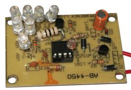
There is no
current limiting resistor on any of the LEDs.
The circuit above takes nearly 1mA when sitting around.
The solution was a simpler circuit that took no current when sitting
around.
The current in the wire loop cannot be reduced to zero, but by adding an
extra transistor, the current can be reduced and the battery will last
100 times longer.
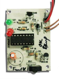
The first transistor is not providing any amplification. It is simply
turned ON by the 470k and the emitter current is the same as the
collector current. When the photodiode detects more heat from a flame,
it passes more current and this turns on the Buzzer.
This is an example of not checking each component to see if it is
needed.
A LED will be damaged if it sees a reverse voltage above about 5v. In
the circuit above the red LED sees more than 310v in the reverse
direction and a current of about 5mA.
This advertisement has one major mistake. The CAPACITY of the
battery is 2400mAhr.
A reader asked me to check his PCB.
It is not my job to check your layouts. I have lots of other things to
do.
The tracks needs to be 100 thou to carry a current of 4 amps.
This is another bad design from Professor Mohan Kumar. The circuit
detects a mobile phone.
More details on this circuit can be found
HERE.
WHAT A JOKE!!
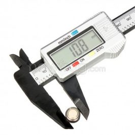
From Alibaba, you can get a DIGITAL CALIPER:
PIEZO DRIVER
You are lucky this circuits works at all.
NO KITS
+12v
The position of the GND. This is the 0v rail and is the
rail where all voltages are measured.
All voltages must be referenced from the 0v rail (called CHASSIS or
earth) as this is where you will place the black probe of the
voltmeter.
KITS N SPARES
Kit cost: $5.00 USD Look at this
mess!!!
Look at the the PC board !!!!!!
240v LAMP
Apart from the fact that all capacitor-fed power supplies are very
dangerous, this power supply will not work because the Neutral is
effectively connected to the earth lead inside the "power point" and
they both rise and fall at the rate of 50 times a second.
Here's more rubbish from TK Hareendran:
For a start, a sealed lead-acid battery with 2 cells has a terminal
voltage of 4.2v and needs to be charged at a minimum of 4.6v. The 1N4007
has a characteristic voltage drop across it of 0.7v. This adds up
to 5.3v.
There is no current limiting resistor on the LED in the circuit above.
D Mohan Kumar has included a current limiting resistor in this circuit.
This diagram shows why a current limiting resistor is needed. The output
is connected directly to the collector of a transistor.
Here's another Indian project:
I don't see any keypad or buttons to change the parameters. What a
useless design !!
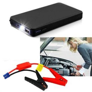
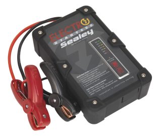
An email arrived today from a manufacturer of BATTERY-LESS JUMP
START POWER PACKS.
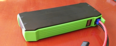
Here is a photo of the supercaps inside the jump starter and the
device itself:
If each supercap is about 6,000 F the final value will be 1,000 F. Each
cell is capable of withstanding about 2.7v to 3.3v.
In this product the cells will experience a voltage of 2v or
slightly more than 2v.
A 40 A-Hr battery has just 40 x 12 = 480watt-Hrs
A 18650 Li-Ion Cell has up to 6A-Hr capacity and a voltage of 3.7v.
The cell
stores up to 80KJ of energy.
No reply from the manufacturer who wanted me to buy 100 units at
$75.00 USD per unit !!
You can see the capacitor discharges to a lower voltage when only a
small amount of energy is delivered. This means the actual amount of
energy that can be taken from a set of supercap cells is VERY SMALL.
A LED requires a voltage that is slightly
more than the characteristic voltage for the LED. Each colour has a
different characteristic voltage that develops across the junction when
the illumination is produced.
This circuit is claimed to be very sensitive
and will pick up very faint audio.
GAMBLING
The internet is full of tricks and "Get-Rich-Quick" schemes that DO
NOT WORK.
The circuit above produces 1.5v for a wall clock.
When the connections in CON2 go open, the 100u starts to charge via
the 470k resistor.
Here is a simpler circuit that takes half the current when "sitting
around" and uses about 40% of the capacitance of the 100u. The 9v buzzer
takes between 25mA and 50mA.
Page 11
Page 2
Page 3
Page 4
Page 5
Page 6
Page 7
Page 8
Page 9
He says: I'm from the MSPP (www.microbee-mspp.org.au)
where we are trying to preserve not only Microbee software & docs but
also all other Australian Made & Designed vintage computers. A number
of our members have talked about the TEC-1 but we don't have info on it
other than what's seen in the
early Talking Electronics magazines.
This computer was ahead of its time for the hobbyist and taught the
basics of Z-80 processors.
You entered the program in Machine Language and it appeared on 7-segment
displays or as sound via the speaker.
There were lots of other
computers coming on the market that did much more and we could not keep
up with progress.
But sales died to a point where we no longer added new projects and now
all the remaining components have been donated.
It's good that everything from the past has been kept by dedicated
people as there is always one in ten thousand people who want to know
how things developed. It doesn't matter if it is the magnetic mine or the
Enigma machine or even the step-by-step relay for the telephone, looking
at one persons inventive qualities can inspire you to do more yourself.
How do you think I became so competent? I looked at other's
achievements.
I became a teacher, printer, TV serviceman, writer, electronics
designer, builder, electrician, plumber, share trader and dog walker.
Look at the latest spaceman. 180 days in orbit. Never finished school.
Don't let education get in the way of your goals and don't let your
goals get in the way of education.
It's wonderful to have both. But passion, perseverance and determination
is the only thing you need.
In one word it is called GRIT.
It's the art of seeing something and sticking to it.
![]()
I get a
number of emails each day from grateful readers and I include them on
the website because everyone wants to know what other's are experiencing
and how they have benefited.
Don't forget, I only get a reply from about one in 10,000 visitors and
the same with orders.
The response from magazine orders, some 30 years ago, was greater than
600 per month from a sales of 12,000 magazines.
But hobby electronics is now a much smaller field and fewer beginners are
taking an interest.
I can understand this as the potential for employment in this area is
considerably less than previously.
However it's a bit like a singing or music career. Not everything is
done with the intention of a monetary reward, and if you have a "bent"
for mechanical, electrical, chemical, musical or geological
investigation, you should take it up, continue and be fully absorbed as
the only way to keep yourself alert is to meet challenges all the time.
Here's an email from Shane:
Hey Colin,,
Shane
Sales Engineer![]()
Your Spot the Mistakes pages are the most wonderful items I ever
came across on the Internet. I read them daily and hold unto them
like a rare talisman. The mistakes pointed out were so glaring and
unnerving that it becomes obvious most professors need to discard
armchair design and/or analysis of electronics. It shows an
incurably defective reasoning, daft mentality and myopic viewpoint
on accepting correction. How do they teach others if they are
unwilling to learn?
But if you observe Nigerian professors you may develop regularly
recurring heartache due to complete non-availability of basic
teaching methods, not to talk of actual knowledge. The most tragic
part of it is most of the textbooks we use here are written by
Indians with no reviews by any electronic or even electric engineer
in the whole country. I know it! Not all Indian engineers are
incompetent but the dimension is severely worrying. This is just the
tip of our iceberg.
Keep on the good work and the Spot the Mistakes section.
Sadiq Shehu Dokaji
Kano University of Science and Technology
Kano State, Nigeria![]()
Firstly, I don't know everything about electronics and secondly I
don't talk about anything that I have not actually experienced
myself.
No matter what you want, it is covered on the web.
It is the greatest learning tool since the text-book and it it
faster, cheaper and more expansive than any book or course.
It is something you have to investigate before thinking a $3,000
course will provide you with the answers. Just because the web is
FREE, does not mean it not informative.
The best things in life are FREE. And the internet certainly holds
this to be true.
But you cannot live by bread alone. You MUST build, build, build.
My wall is filled with boxes of prototypes.
No kit is released without firstly building a prototype and then
putting a kit together.
A kit must be able to be put together without any external
assistance. The legend on the top of the board must identify
everything for it to be successful.
You will see many projects in this section (from other people) with blank PC boards or
parts crammed in a corner or leads all over the board.
This sort of design is quite unsatisfactory.
These boards need a re-design and may be done with a double-sided
board. But none of your half-finished work should appear in a
magazine. The quality of the board shows the capability of the
designer. And some designers have NO capability.![]()
It happens EVERY time.
This time it has happened with the PIC chip and Arduino.
Arduino projects use the AVR family of chips from Atmel and PIC released
their first chips in 1976 while the AVR chips were first released
in 1996 so the developers had 20 years to look at what had been
developed in the microcontroller field.
I am not saying the concept was copied but the similarities of the two
designs are almost identical.
MERE CO-INCIDENCE !!!
However the annoying part is the take-up of the Atmel chips by a group
of individuals who shared their ideas and projects and programs as an
open-source venture.
This had enormous impact on the development of projects for this range
of microcontrollers and very soon the focus was taken away from PIC and
concentrated on the ATmega range of micros.
I can understand the pointlessness of having two streams of designs to
cater for each range of chips but it would be a simple matter to produce
a conversion program to allow a program to be sent to either range.
This would have prevented PIC chips from falling by the way-side and
becoming almost no-existent in any of the hobbyist robotics areas.
Microchip (PIC) has done nothing to enthuse the hobbyist and encourage
the use of PIC chips and even the programmer is inordinately expensive.
There is nothing from Microchip to get you started.
They don't even produce a socket so the 8 or 16 pins chips can be
programmed. Neither do they have the instruction-set printed in
easy-to-understand format or a library of routines to help you produce a
program.
Everything comes in the form of APPLICATION NOTES and you have to be a
professional programmer to understand what they are saying.
That's why do you do not see any simple projects using a PIC chip.
Even a simple project comes from someone who really understands
programming.
My idea is to produce a programming book with a free PIC programmer on
the cover. Clones are already available on the web for $12.00 posted and
mass-production would reduce this to $6.00 for Microchip.
I wonder if Microchip will ever wake up to the enormous potential they
missed out on. ![]()

![]()
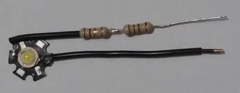
Two 1 ohm resistors in series!!
The resistance should be 4.6 to 5.6 ohms - NOT 2 ohms !!!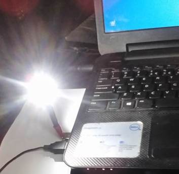
To find out the actual voltage for the LED you are using,
connect a 10 ohm resistor in series and connect to the USB port.
This will allow less than 100 mA to flow and you can quickly read
the voltage across the LED.
The current through the LED MUST NOT be more than 300mA because we
are not heatsinking the LED and it will get very hot.
If you connect two 1-ohm resistors to the LED, the current will be
5v - 3.3v = 1.7v / 2 = 850mA !!!
If the characteristic voltage is 3.6v, the current will be 1.4 / 2 =
700mA !!!
The correct resistor-value is:
5v - 3.3v = 1.7v / 0.3 = 5.6 ohm
If the characteristic voltage is 3.6v, the resistance will be 5v -
3.6v = 1.4v / 0.3 = 4.6 ohm
The value of resistance is very critical.
You will also find the resistors get hot as about 400mW will be
dissipated.
![]()
LED TUBE
More bad advice from Professor Mohan Kumar: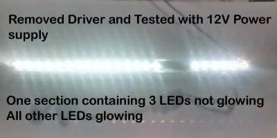
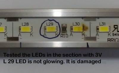
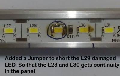

This is NOT how to repair a LED TUBE or any LED device contain a
number of LEDs in series.
Most of these LED items drive the LEDs at maximum brightness and
thus they deliver the maximum current through each of the LEDs.
This current is controlled (limited) by a "dropper resistor" and the
value of the resistor has been worked out by knowing the voltage of
the supply and the natural characteristic voltage drop across each
of the LEDs in the string.
The current should be 17mA for very long life, 20mA for good
brightness and 25mA maximum to get the maximum brightness.
If the supply is 12v, the characteristic voltage drop across each
LED will be 3.2v to 3.6v and using 3.4v as the average, the total
LED voltage will be 3.4v x 3 = 10.2v.
This will leave 1.8v for the voltage across the dropper resistor.
If 25mA flows, the resistance of the dropper resistor will be 72
ohms.
If we remove one of the LEDs, the characteristic voltage-drop across
two LEDs will be 6.8v.
This means 12v - 6.8v = 5.2v will now appear across the 72 ohm
resistor.
The current flowing through the resistor will be 72mA.
The two LEDs will not appear to be any brighter because they were
originally producing maximum brightness, but the current is now far
greater than the LEDs will tolerate and they will very quickly BURN
OUT.
This is simply another ignorant design by Professor Mohan Kumar, who
consistently delivers bad information on the web.
That's why you have to be careful when searching the net, to avoid
disastrous comments like this.
![]()
Input pins 2 and 6 are very high resistance inputs.
This means it is exactly the same as connecting a zener to
"nothing."
In other words the cathode goes to the 10mF and the anode is
"floating."
The zener diode consists of a crystalline structure and it has a
very high resistance.
Because the anode is not connected to anything, it will rise to
exactly the same voltage as the cathode.
This is how you look at the circuit.
Now you can see why it will not work.
![]()
No-one on the forum found the mistake.
The motor never reverses. What is the problem?
HINT: The first relay "pulls-in" but does not release.
When the first transistor is turned OFF, the second transistor turns
ON and the second relay is energised.
The base current for the second transistor passes through the first
relay and the 1k resistor on the base will allow about 10mA to flow
through the relay.
This will keep the "clapper" energised and it will "stick" to the
pole of the relay and prevent the motor reversing.
The solution is to increase the 1k to 47k and the current through
the relay will be so small that it will "de-energise."
![]()
MOBILE PHONE EMERGENCY CHARGER
All mobile phone emergency chargers are really a waste of
time.
But in this article we will explain how to relate the capacity of
the emergency battery to the phone battery.
There are two types of emergency chargers.
The complex type uses a switch-mode circuit to convert the energy in
the emergency battery to charge the mobile phone.
If the emergency battery is 1.5v alkaline cell and has a capacity of 2,400mAhr,
and the phone battery is 3.7v @ 1,800mHr, the battery 1.5 x 2,400 mWHr
= 3,600mWHr will half-charge the phone battery (6,600mWHr).
If the battery is 9v and a simple regulator is used to charge the
phone battery, you will only pass half the energy of the 9v battery
because when the battery voltage drops below about 5v, no charging
current will flow.
A 9v carbon-zinc battery is rated at about 200mAHr when delivering
15mA and has a lower capacitor at say 100mA.
However if we used this type of battery only about 100mAHr to
150mAHr of energy will pass into the phone battery. This is only
about 5% to 8% charge and is hardly worth-while. A 9v battery costs
about $1.00 and it is an expensive way to charge a phone.
![]()
When will Electronics For You get a technical editor ??
Here is a circuit from August 2016 magazine:
This is a very important component and MUST be included.
The output FETs on the microcontroller are very small and are
designed to deliver about 20mA maximum.
When they are turned ON, the voltage across them is less than 0.5v
and thus 10mW is being dissipated.
When a resistor is NOT included, the FET can only "pull down" by an
amount equal to the characteristic voltage of the LED in the
display.
For a red LED, this voltage is 1.7v and for a white LED it is 3.4v.
The voltage across the collector-emitter terminals of the transistor
will be less than 0.5v and this means the voltage across the FET
will be between 2.3v and 0.6v
BUT because the FET is sinking in this type of circuit, the current
will not be limited to 20mA but will increase to about 40mA because
the LED is acting like a zener diode and it is just like putting a
2.3v supply-rail on the pin of the micro and asking the micro to
pull the 2.3v lower.
The dissipation of the FET is now 80mW and this is 8 times greater
than before.
It is lucky the micro is very tolerant, but if you were to do this
in a high-current situation, the result would be premature failure. ![]()
LOOP ALARM
Here's another bad design from Professor Mohan Kumar:
If you use a 9v battery, it will last about 200 hours. That's
about 10 days !!
This type of fault was one of the reasons for the introduction of this
series; SPOT THE MISTAKE. On page 2 you will find a KEY HOLE LIGHT
that took only a fraction of a milliamp when sitting around but the
battery went dead in 3 months and the project was a failure.
Here's the circuit:
This circuit has now been turned into a project:
KEY HOLE LIGHT
Here is the circuit:
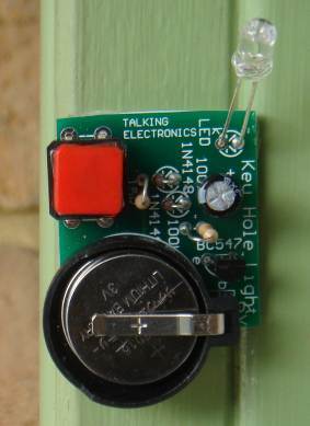
Key Hole Light kit can be bought from Talking Electronics
![]()
IR ALARM
Here's another bad design from Professor Mohan Kumar:
But the first transistor can be removed and the circuit will work
exactly as before. It is not needed:
![]()
LED will BLOW UP !!!!
Another bad design from Professor Mohan Kumar.
He does not test ANYTHING !!!!!
![]()
3.6V 2.4A
Lithium Thionyl Chloride Battery
ER14505
* Lithium Thionyl Chloride Battery
* Size: AA
* Volts: 3.6V
* Current: 2400mA
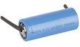
The recommended discharge current is 100mA.
It is NON-RECHARGEABLE.
Always check specifications of a product before buying ANYTHING.
Check out the details on other websites.
![]()
He said the positive track had brunt out.
All the tracks (called traces) are far too thin (narrow) for a
high-current project. The tracks to the output transistors and the power
supply will be taking between 1 and 5 amps.
Normal Printed Circuit Board has 1 ounce of copper per square foot and
this corresponds to 1.4 thousands of an inch thickness.
80gsm paper is 4 thousands of an inch thick, so you can see how thin the
tracks are.
The thinnest (called narrow) tracks on a normal PC board are 10
thousands of an inch (called 10 mils) and this will carry 1 amp. (I
would never take the risk. Use 20 thou or 25 thou). 
The tracks on the board above are 25 thou (wide) and need to be 4 times
thicker (WIDER) to carry the current.
You can either use printed circuit board having 2oz copper, increase the
track width or solder 0.5mm tinned copper wire along the high-current
tracks. ![]()
DETECTING A MOBILE PHONE 
I do not know if it is successful or not.
1.
Mobile phones operate at 2-3GHz and a 1N60 diode will not function
at this frequency.
2.
What is the purpose of the 0.22 on the antenna????
He says: "To
capture the RF energy from the Mobile phone, a Diode � Capacitor
combination is used along with the Antenna. Diodes 1N60 capture the
RF energy from the active phone and capacitor C1 stores this energy."
How
can a capacitor store energy and deliver it to the circuit when only
one lead is connected to the circuit ???
Here is a circuit using a very high-speed diode. This circuit
works:
![]()
A major electronics supplier is selling a venier caliper:
(What is a venier caliper ???)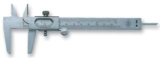
![]()
The piezo speaker is actually a 22n capacitor. When the transistors
turn ON, the capacitor charges. When the transistors turn off, what discharges
the capacitor ??? Nothing.
When the transistors turn on again, the capacitor is already
charged. That's why the output from the piezo will be very small.
It would be better to drive the piezo directly from the output of
the microcontroller. At least the output will be push-pull and this
will charge and discharge the 22n capacitor to produce a loud
output.
Why use 2 transistors ?
You lose about 1v across the Darlington pair.
Just a bad design from a person who has not studied electronics.
![]()
I downloaded Sept 2016 issue of ELECTRONICS FOR YOU and linked to 3
suppliers of kits.
The 3 websites had no images of any kits. No kit details and no
prices. Why spend money on a magazine advertisement and not back-up
the "fancy ad" with availability of kits. Where are the Robot
kits? Where are the 400 Educational kits?
The magazine is full of HYPE. They simply regurgitate electronic
developments from around the world and fill the pages with "wishful
thinking."
Instead of presenting MADE IN INDIA, they say: MAKE IN INDIA.
Who would bother to make anything in India when there is no
infrastructure.
None of the projects are available from the magazine and none of them have been photographed with the PC board. Only matrix-board
prototypes are shown.
No-where in the magazine does anyone offer a PC board or request a
PC board. It's all just a dream.
![]()
The following circuit is classified as a DUAL RAIL SUPPLY.
The main points to note are:
Note the minus 30 rail. This the only rail we are interested
in.
.gif)
The voltages on the 7805 will be minus 18.6v and minus 25v.
Neither of the voltages will be stable as the minus 30v rail (line)
is not stable.
The 7805 voltage regulator will have no effect on stabilising the
voltage. ![]()
This is the sort of rubbish from the kit section of ELECTRONICS FOR
YOU:

Postage costs: $334.00 !!!!
Look at the electrolytic !!!
No IC markings. No IR receiver markings.
All my staff produce better boards than this. These boards are
absolutely ghastly.
How can a magazine allow rubbish like this to be sold to
experimenters ?????
Electronics For You is giving away their magazine each month.
If you subscribe for 12 issues, they give you a discount. Then
they send you a multimeter and finally you have to only pay $1.75
for 12 issues.
The postage alone would cost them more than $2.00 !!!!
It reminds me of POPTRONICS with a $19.00 subscription. They paid
the subscription-house $6.00 and got $1.00 per issue. The
postage would have been more than $1.00 per issue. Finally
they went bankrupt. ![]()
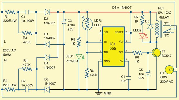
Look at the circuit diagram.
The Neutral and the earth are both connected to the circuit.
This means there is a "piece of wire" connected between "N" and the
"GND" on the circuit.
This means the lower 220R resistor, 1u 470k and D3 can all be
removed and replaced with a piece of wire, because none of the leads
rise higher than 0v.
Now we have D4 not doing anything so it can be removed.
Now we have the "L" wire (the live or LINE) rising to 340v and then
falling to minus 340v while the "N" wire remains at 0v AT ALL TIMES.
When the "L" wire is rising, it is delivering an average of 70mA and
when it is falling, the capacitor is being discharged through D1.
This means
There is no zener diode in the circuit to control the voltage
produced by the capacitor, however the components produce a load and
this will reduce the voltage to some unknown value.
The first LED will take about 5 to 10mA and the 555 will take 10mA.
This leaves 20mA. When the output turns ON, the second LED
will take 5 to 10mA.
Where is the current for the relay ???
Just another junk circuit from Mohan Kumar.
![]()

It is an untried, untested, un-workable, idiotic design. 
USB ports deliver EXACTLY 5v. How is this going to charge the
battery ??????
A Piranha white LED requires up to 180mA.
The 4066 IC will deliver 10mA from each output at 5v. How is this going
to illuminate a LED?
Why not use a simple transistor circuit ???
How can ELECTRONICS FOR YOU (October 2016) publish such a JUNK
CIRCUIT ?
Simply because they have no technical engineers.
All the gloss and hype in the magazine means absolutely NOTHING.
It is all commandeered from other sources and cobbled together to make
it look like India has an electronics industry.
It's all: "copy this" and "steal that."
Instead of MADE IN INDIA, they promote: MAKE IN INDIA.
India wants $120.00 USD for a PCB panel I get made in China for
$25.00. (postd)
India has copied a number of IC's and transistors, but NON-ONE SELLS
THEM !!!!
India has no infrastructure.
There are 6 advertisements for kits in Electronics For You
October 2016, but when you go to the websites, nothing is available.
Two of the biggest kit manufacturers have disappeared !!!
Another 4 suppliers do not send kits overseas and 3 more want $25.00 to
post a $5.00 kit !!!
China hast post-free options.
China has Alibaba.
China has infrastructure.
China actually DELIVERS.
India is living in a dream-world. I have tried for 2 years to get a
reply from India. NOTHING !!!!
Not one thing has been sent to me from India.
![]()
Here's another disaster:
![]()
A GREENHOUSE ENVIRONMENT CONTROL PROJECT: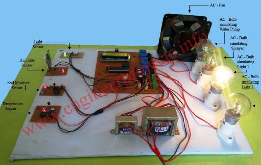
![]()
This is Jenny from
Powerstarter. We'd
like to introduce our
World's First
battery-less car jump starters.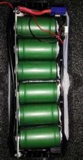
This email caught my attention and I replied with some
questions.
It took quite a while to get them to admit the product was a
supercap storage and there are a number of products like on the
market. So, there are not the World's First !!
I asked how much energy the device will store.
Their reply was: Now each 12V
product can store 6627 KJ energy
I converted this to watt-hrs and replied as follows::
6627 KJ = 1840 watt-Hrs
A nearly flat 40A-Hr battery will have less than 200watt-Hrs
You only need 12 x 200amps x 10 seconds = 7watt-Hr to help start a car.
Why employ supercaps with 1840 watt-Hrs storage?
It will take more than 90 minutes to fully charge the supercaps at 100
amps and this will be an impossible task.
Their reply:
Our 12V Car jump starter can store 13.5KJ each, as 3.75Whr.
Finally, they admitted their mistake. 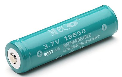
The supercap Jump Starter stores less than 25% of the energy of a 18650
cell !!
The size of each supercap is not known however from the storage of
3.75W-Hr for a 12v system, we can work out the effective capacitance is
1,130F at 12v.
If there are 6 supercaps in series, each supercap must be 1,130 x 6 =
6,780F
Let's see how a jump starter works.
When you take energy out of a car battery, the voltage decreases.
The voltage of a fully charged car battery remains at 12.6v for at least
the first 25% discharge. After that, the voltage drops at a gradual
rate.
Some starter motors need 200 to 350 amps and even 450 amps on a cold
day.
Some of the newer starter motors have a gear reduction and they revolve
at a fairly high RPM with the gears increasing the torque. These
types of starter motors only require about 120 amps to 160 amps.
But when a car battery is not fully charged, the terminal voltage drops
from 12.6v to as low as 8v depending on its age, the temperature, and
state of charge.
This reduced voltage will deliver lower current to the starter motor
and that's why the car will not "start."
The battery is capable of delivering a higher current but because the
voltage is low, the result is a lower current to the starter motor. If
you simply put another battery across the car battery, its voltage will
rise due to it getting slightly charged by the jumper battery and it
will now deliver a higher current. We haven't charged the car battery,
we have simply put a higher voltage across the battery and this raises
the voltage of the car battery very quickly. It's called a FLOATING
CHARGE VOLTAGE.
Now let's look at the starter motor requirements:
For a 350 amp starter motor on 12v, the wattage will be 11v x 350 = 3850
watts.
The resistance of the starter motor = 12/350 = 0.034 ohms
When the voltage drops to 8v, the current will be 8/0.034 = 235 amps
The wattage will be 8 x 235 = 1880 watts
The starter motor will have slightly less than half the output power.
This applies to both types of starter motor but the high-current starter
motor will be the biggest problem.
The problem is the drop in terminal voltage of the battery.
If the terminal voltage can be increased, a higher current will flow and
the starter motor will "crank the engine."
Along comes a JUMP START.
A jump start is the art of connecting another (fully charged) battery
across the car battery.
This Jump-Start battery does two things.
It increases the terminal voltage of the system (the voltage seen by the
starter motor) and it will supply some of the current.
When the jump-start battery is connected, it immediately starts to
charge the car battery and it produces a terminal voltage of 12.6v
within a few seconds.
The charging current will only be a few amps and does not come into the
discussion.
However the terminal voltage is now 12.6v and when the starter motor is
connected, a high current will flow.
The actual value of the current and the proportion from each battery is
unknown but the end-result is quite impressive and the car starts
immediately.
The supercap starter works on a slightly different principle.
Firstly, the capacitors are uncharged because supercaps have a high
leakage and they would be flat after a few months.
So you cannot store the "jump-starter" product in a charged condition.
Secondly, the capacitors present a short-circuit when the jumper clips
are initially connected to the car battery and a very high current will
flow. And sparks will fly !!
The supercap will charge in a few seconds (up to about 15 seconds) and
although this current is high at the beginning, it rapidly drops to a
few amps.
Don't forget we are only storing 25% of the equivalent energy of a 18650
cell.
I don't know whether the product has a circuit to increase the voltage
of the supercaps above the voltage of the battery, but let's say it
does.
The supercaps get charged to 13v.
But a supercap jump starter works differently to a li-ion jump starter.
When you discharge a Li-ion battery, the terminal voltage remains fairly
high over the short time-span of starting the car.
But the voltage across a super-capacitor drops proportionally
(immediately) as the energy is
released.
This means the 12.6v is only available for a fraction of a second.
This means the actual energy in a supercap system is much smaller than
any of the figures provided by the manufacturer:
Normally it will take 3 to 4 seconds to start a car,
12V x 200A x 3s = 2WHr
12V x 200A x 4s = 2.67WHr
12V x 200A x 5s = 3.3WHr
These figures may be correct, but the useful energy from the product is
not 3.75W-Hrs but less than 1W-Hr because the peak voltage drops off
very quickly. .
The product is working on the extreme end of its capability and it would
be much better to invest $30.00 in a power pack containing a 12v li-ion
battery.
All of the Jump Start devices are working on the extreme end of their
capability by delivering 100 amps or more during starting.
Fortunately the action takes place over a few seconds as the battery
heats up considerably during this operation.
However the 12v Li-ion pack will allow you to start the car about 10 times before
it requires a re-charge and will certainly deliver more than 4W-Hrs per
use as the battery holds more than 250KJ of energy.
There is no comparison between the two concepts.
From an electronics standpoint, a supercap product is not suited to this
type of application. The voltage on a capacitor drops as soon as energy
is taken from it whereas a battery has a much lower rate of drop.
I know manufacturers are desperate to find an application for a
supercap, but this is not a realistic application.

 |
|
It is equal to 0.27AHr 12v battery !!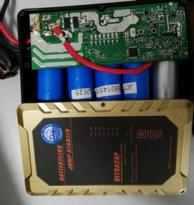
Note the enormous amount of electronics.
And there is no same product on the
market now as the design is fully new.
NO. It is NOT !!!
And there are many similar USELESS products on eBay !!
Buy a 4.5A-Hr battery and keep it in the boot of the car. It will
cost less than $20.00
WHY A SUPERCAP JUMP STARTER IS SUCH A SILLY IDEA
The following two graphs show how a capacitor discharges and how a
battery discharges.
A jumper battery will deliver a lot more energy before the
voltage drops to a level that is not accepted by the starter motor.
Using a super-cap jump starter is just a complete waste of time
and money. All the trick in the book will not get past the fact that is
just a waste of time to consider buying one.
![]()
John Darke here in SW Florida with a quick question.
Just got into LEDs with setting up a solar panel with a 12 volt
system. We purchased a bunch of RGB colour changing LEDs that were
pre-wired (560 ohm resistor wired in series).
We place about 25 of these in series around our pool cage and 6 of them
IN PARALLEL inside of a tiffany lamp which also has two 10 watt halogen
lamps with a separate on/off switch.
I would love to learn the theory on all of this and your web site looks
terrific and I started to read through the LED portion when I came
across you section about wiring LEDs in parallel.
Our problem is that 1.) when the halogen lights are turned on, all the
colour changing LEDs revert to red and stay red. When the halogen lights
are turned off the 25 in series begin changing normally but the six in
the Tiffany lamp stay on red and don't change.
Would appreciate your comments as we are having guests fly in a week and
hoping to get this thing figured out.
By the way, when I put the Tiffany lamp on an independent battery, the
LEDs work properly whether the halogen lamps
are on or off.
This problem is mainly due to the voltage required by a LED.
A LED is not a globe.
It is very difficult to deliver this EXACT voltage so we add a resistor
and supply the combination with a slightly higher voltage and the LED
produces the exact voltage it requires and the extra voltage is dropped
across the resistor.
If you increase the supply voltage, the extra voltage will appear across
the resistor and this will cause more current to flow and this current
will also flow through the LED and increase the brightness.
For 3mm and 5mm LEDs, this current should be between 17mA and 25mA,
however it can be as low as 1mA for super-bright LEDs.
In the problem above, we do not know the exact voltage provided by the
12v solar panel and we do not know the current it will deliver.
When a solar panel is in bright light, it can produce up to 50% more
than the rated voltage, it just depends on how many solar cells have
been included in the panel.
Each solar cell produces about 0.5v to 0.6v and some manufacturers
include extra cells so the output will drop to the voltage specified on
the label.
In all cases, the output voltage will drop when you take more and ore
current.
A solar panel is not a fixed-voltage device. It rises and falls with the
intensity of the sun and the load.
However a 12v "string of LEDs" is a fixed voltage device.
The 560 resistor is not 560 ohms but 56 ohms because 560 is
printed on the surface-mount resistors and this is read as 56 with no
zeros.
When the string is supplied with 12v, the LEDs in the string have
individual characteristic voltages.
If the resistor is 56 ohms and we want about 25mA max current, the
voltage across the resistor will be 1.4v
This means the total characteristic voltages of the LEDs must add up to
10.6v.
As the supply voltage is reduced from 12v, it drops to a point of 10.6v
This means no voltage will be dropped across the resistor and thus no
current will flow.
However, as the voltage drops and the current reduces, the
characteristic voltage of each reduces a small amount and the LEDs get
dimmer and dimmer. Some LEDs stop working and it appears the red LEDs
still give a small amount of illumination.
![]()
SENSITIVE AUDIO
DETECTOR
This may be true but you have to remember the transformer is reducing
the amplitude of the audio to 5% of the original amplitude.
The maximum audio into the transformer will be 700mV (due to the diodes) and thus the output
will be 35mV max.
This arrangement is NOT the way to make a sensitive audio detector.
It needs an active device such as a transistor or op-amp to get a really
loud output.
But the circuit introduces a very interesting discussion.
Why include the diodes? They simply reduce the output for no reason.
Removing the diodes will increase the output in most cases.
The 1k resistor is intended to reduce the load on the signal but it
simply reduces the signal appearing on the input of the transformer by a
larger factor than if the transformer was connected directly to the
signal.
SOME BACKGROUND THEORY
Whenever you use a piece of test gear, it puts a load on the circuit you
are measuring.
The result is the amplitude of the signal is reduced. It may be reduced
by 1% or as much as 90% and in most cases you are not aware of the
amount of reduction.
All signals have a certain amount of "strength."
This basically means they are capable of delivering a certain amount of
current, along with the amplitude of the signal.
We refer to these signals as "strong" or "weak" (or delicate), according
the the current they are able to deliver and we can explain this further
by saying a 3v peak-to-peak signal developed across a 1k resistor will
be "strong" compared to the same signal developed across a 100k
resistor.
The reason is this: It will take a flow of 3mA to produce 3v
across a 1k resistor, but 0.03mA will produce 3v across a 100k resistor.
This means there will be a flow of 3mA in "circuit A" and if your piece
of test gear takes 0.1mA when taking a reading, there will be 2.9mA
remaining the circuit being tested.
But if we try to take 0.1mA from a circuit that has 0.03mA flowing, we
will reduce the amplitude of the waveform considerably because the
signal will not be able to delver the 0.1mA current. We cannot give any
absolute values in this discussion but just an idea of what will happen.
Now we take the transformer in the circuit above.
We have already said the diodes are really pointless and now we come to
the 1k resistor.
The resistance of the primary winding will be about 50 ohms to 100 ohms
but when it is connected to an audio signal the primary will appear to
be about 1,000 ohms to more than 4,000 ohms depending on the quality of
the transformer.
This is the IMPEDANCE or the VALUE OF IMPEDANCE or the IMPEDANCE VALUE.
If you remove the 1k and the diodes, the input impedance of the
transformer will be just about the same as the circuit above (as the 1k
makes very little difference to the overall input impedance of the
project) and now you
will get more of the signal appearing across the primary.
This will improve the audio in the headphones.
By removing the diodes, the audio in the headphones will increase by a
factor of up to 10 times and now you have something that will work to
detect faint signals.
If you put the headphones directly across the "signal source" you will
"kill" the signal.
In most cases the signal will be reduced considerably because the
headphones need something like 20mA to 50mA to move the diaphragm.
What the transformer does is this: It converts a high voltage that has
very little current-capability to a lower voltage and increased current.
In simple terms, the voltage will be decreased by a factor of 20 and the
current will be increased by a factor of 20.
But, although the transformer will be capable of delivering a high
current to the headphones, it is the voltage that will determine the
actual current that will flow to the headphones.
If the input voltage is 5v, the voltage to the headphones will be 250mV.
If the impedance of the headphones is 16 ohms, the current into the
headphones will be 16mA. The output of the transformer may be capable of
delivering more than 16mA, but the headphones will not "accept" more
than 16mA.
This all comes to the important question.
Does the transformer increase the audio? In other words, does it produce
a louder result than if the headphones were connected directly to the
circuit.
With the 1k and diodes removed, the transformer will put a small load on
the signal (compared to connecting the headphones directly to the
circuit) and this will allow the amplitude of the signal to be
maintained.
It will be reduced a small amount and the actual attenuation will depend
on the "strength" of the signal.
But, as we have already shown, a 5v signal will only produce 250mV and
only 16mA will flow through the headphones. You will have to try the
circuit and see if it produces good results. You can compare it with a single transistor in a common-emitter stage in
place of the transformer and work out which arrangement is best.
REMEMBER THIS:
Whenever you use a piece of test equipment, you will not be seeing the
absolutely correct and accurate shape of the signal.
This is due to the probe having a value of resistance or impedance that
will modify the signal.
That's why you try to use a probe with the highest value of resistance
or impedance.
But these pieces of test equipment are expensive.
For instance, a Cathode Ray Oscilloscope (CRO) rated a 10MHz will
attenuate the signal and reduce it to 50% when the signal is 10MHz. You
only see half the amplitude.
A 30k/ohm analogue multimeter will have a resistance of 300k on the 10v
scale and if you are measuring across a 1M resistor, the voltage will be
reduced considerably, depending on how the reading is measured.
When you connect a piece of test equipment, the circuit becomes two
parallel components. Depending on the shape of the signal and the
frequency, the signal can be altered to a point where the circuit stops
working.
This can be the case with 100MHz oscillator such as an FM transmitter.
Probing the oscillator with a multimeter will turn the lads into an
antenna and draw away so much of the signal that the feedback section
will not work and the oscillator will freeze.
If the test gear has a capacitor in the probe, this capacitance may
upset the shape of the signal.
When ever you are dealing with weak signals or high-frequency signals,
you must remember that probing different parts of the circuit can change
its operation considerably.
![]() It actually takes a lot of understanding to "see" what is happening when
the circuit above is connected to a project.
It actually takes a lot of understanding to "see" what is happening when
the circuit above is connected to a project.
That's because it uses a transformer and the windings have two
completely different values. Each winding has a resistance, measured in
ohms and this can be determined with a multimeter set to Ohm's.
But when an AC signal is connected to the input, the rising and falling
voltage produces a back voltage that comes from the magnetism produced
in the metal core of the transformer. This voltage can be as much as 99%
of the incoming voltage and it prevents current flowing into the
transformer. It makes it appear that the "resistance" of the transformer
is very high because if we replace the transformer with a high
resistance, the incoming voltage would rise and very little current
would flow into the resistor.
But we also have a secondary winding and this is connected to a set of
headphones. To make it easy we will say the output impedance of the
transformer is 16 ohms and this connects directly to 16 ohm headphones.
Now we have a 16 ohm load but we will call it just a LOAD.
When the rising voltage enters the transformer, it produces magnetic
flux and this flux cuts the turns of the secondary and produces a
voltage and current.
This means some of the magnetic flux is converted to drive the
headphones and thus it is not available to oppose the incoming voltage.
This means the opposing voltage will not be as high and thus more
current will flow into the transformer.
The amount of current will depend ion the number of turns on the primary
winding and the number of turns on the secondary as well as the
efficiency of the transformer.
And all this will change as the frequency increases.
So, it is a very complex situation and all you need to know at the
moment is the fact that the headphones are a load on the circuit and
they take away some of the magnetic flux, however some of the magnetic
flux remains and this opposes the incoming voltage to make the
transformer appear to have a much higher resistance - and we call this
IMPEDANCE. ![]()

However the latest craze is to make money on the stock market via buying
and selling shares on the short-tem basis.
It is called "leveraged buying" and you put down 10% of the value of the
shares and reap the rewards of the TOTAL profit.
It works like this: Suppose a share is $50.00 and you buy 1,000 shares.
It costs you 1,000 x $5.00 = $5,000.
Suppose the share goes to $52.00 the next day. You get your $5,000 plus
$2,000 PROFIT.
The costs of buying the shares will be about $100 and the cost of the
"bank" supporting 90% of the costs of the shares will be about $45,000 x
10% interest x 1/365 for 1 day = $13.00
But suppose the shares fall to $48.00. Your $5,000 becomes
$2,887.00 You lose $2113.00 in just one day.
Now you don't have enough money to buy 1,000 shares and you can only buy
577 shares. If the shares rise, you will not get back to your $5,000.
Of course the stock market is rising and it need lots of "mugs" to keep
investing to keep it rising.
Even if you have a "seat on the floor" and watch the market go down, you
will see the sale of your 1,000 shares depress the market even further
and you have no control over the outcome.
If the market drops $5.00, the stock broker will sell the shares for you
and you will have to pay the buying and selling costs as well as the
"bank interest." You will have LESS THAN NOTHING in a few days.
In most cases your shares will be sold at minus $4.50 and you will be
out of the market.
None of this is explained clearly to MUG PUNTERS.
You are not "buying shares" you are GAMBLING.
Before you invest ONE PENNY. Look up the share market, select 10
companies and invest $10,000 in each company with MONOPOLY MONEY. Record
your profit and loss EACH DAY and come to a conclusion at the end of 2
weeks.
You must trade EACH DAY because a loss can wipe out a company in one
day.
Your $100,000 will be worth less than $80,000 and you will wonder:
"WHERE DID I GO WRONG!"
On 50:50 toss of a coin, humans can only get it right 47 times out of
50.
That's why casinos and horse-racing thrive and stock markets make money for the stock
brokers.
We can never get passed "47 out of 50" DECISION MAKING.
Try a simple "coin toss" yourself or the "roll of a dice" and if you get
55% or more, you can trade shares.
![]()
Some things are not worth "electrifying."
A 1.5v cell operates for 12 months and it is not worth the effort to
convert it to operate from the mains.
But the hidden danger is the circuit is connected DIRECTLY to the mains
and anyone taking the clock from the wall can get a shock if they touch
any of the electrical wiring.
The 2 ohm resistor does NOTHING to limit the current and the circuit is
VERY DANGEROUS.
![]()
SUITCASE ALARM
Here's another terrible design from ELECTRONICS FOR YOU, November 2016,
by Pradeep G:
But the 470k, diode, 100k pot and base-emitter junction of the
transistor form a voltage divider circuit.
Remove the diode and base-emitter junction, and the 100u can only charge
to 100k/470k = 21% of rail voltage ! This is 1.9v and the transistor
will not work below 0.6v. This give 1.3v range for the delay period.
A very poor design.
In addition, the 1k on the base of the BC546 allows 8mA to flow through the
base. You only need 2mA.
As I have said before, there are NO electronics staff at ELECTRONICS FOR
YOU to look at simple designs like this and see how poorly they are
designed.
It's just a JUNK MAGAZINE.
The article states: Normally, vibration sensor terminals are shorted internally. When the suitcase is lifted, sensor terminals momentarily open.
There are many different types of vibration sensors and tilt sensors.
Make sure you fit the correct type.
![]()
![]()
Page 10
Page 11
Page 12
Page 13
Page 14
Page 15
Page 16
Page 17
Page 18
Page 19
Page 20
Page 21
Page 22
Page 23
Page 24
Page 25
Page 26
Page 27
Page 29
Page 30
Page 31