See our article on the
INDUCTOR
INDUCTANCE
is what an INDUCTOR has. It has
INDUCTANCE. It has the ability to store energy in the form of
magnetic flux and this energy can be stored in the CORE (the
MAGNETIC CORE). Inductance is measured in Henry (H) , milli-Henry (mH) and
micro-Henry (uH). An INDUCTOR is a coil of wire and it
may be wound on a plastic former called a BOBBIN and the centre
of the bobbin can be filled with a magnetic material called a
CORE or MAGNETIC CIRCUIT. Inductance is a unit of storage,
just like a battery has a storage of amp-hours.
INDUCTANCE
We are talking about how much energy
can be stored by a coil of wire, called an INDUCTOR.
It has the units of: Henry (H) , milli-Henry (mH) and
micro-Henry (uH).
But our
discussion starts with a length of wire.
An amazing thing that happens when it is
connected to a battery.
When a current flows through a piece of wire it produces magnetic flux.
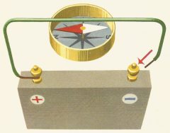
You can see this effect by placing a wire over a
compass - the needle
moves slightly.
To increase the movement of the needle, lots of turns
of wire are wound on a cardboard
tube (called a former).
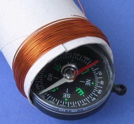
By increasing the number of turns, the needle will rotate more.
Don't worry about which way it rotates or how much it rotates,
the needle shows magnetic flux is being produced by the
coil.
This is how we draw the magnetic
lines produced by the
current in the coil. The lines emerge from one end of the
rod, pass around the outside and enter the other end.
These lines make it easy to describe what is occurring.
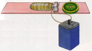
By winding the coil on a nail, screw or bolt, the magnetic flux
from each turn is added together (called concentrated) and comes out
the end of the bolt.
These experiments were demonstrated over 100 years ago and
everyone thought they were amazing.
It was the first time electricity had an effect on moving an
object.
Now we come to something that is more amazing.
When the switch is closed (called a knife switch), the compass
needle moves slightly clockwise and then returns to "North."
When the switch is opened, the needle moves anti-clockwise and
returns to "North." The "up-down" position of the
needle is simply to set it so it can move clockwise and
anticlockwise.
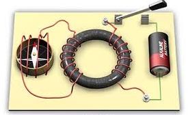
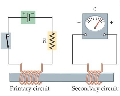
When this was demonstrated over 100 years ago,
there was no other test equipment and the demonstrator Michael
Faraday concluded that voltage was induced in the compass coil -
in one direction - when the switch was closed and induced in the
other direction when the switch was opened. The two coils did
not touch each other and the only thing connecting them was
magnetic flux through the ring. (the ring is called a ferrite
ring or fine powered iron ring.)
This is also shown in the following two diagrams:

Here's the next amazing feature.
When you turn off a circuit containing a coil, a very high
voltage appears across the ends of the coil.
You can feel this by connecting 12v to a relay and hold the
wires in your two hands. When you remove the wires, you will
feel a zap.
You can also connect the relay as shown in the diagram below so is buzzes when the voltage is applied. Feel the terminals
by pressing firmly with your fingers and you will get a zap.
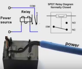
This means the 12v is converted to at least 80v
to give you a zap.
How does this happen???
The relay contains a coil of thousands of
turns.
When you connect the supply, the coil produces magnetic flux
(commonly called magnetism).
When you remove the supply, the magnetic flux collapses and cuts
all the turns of the coil and produces a very high voltage IN
THE OPPOSITE DIRECTION.
This means a coil has 2 uses. It can deflect a compass needle or
pick up nails or scrap metal to load into a ship etc or it can
be used for its ability to produce a high voltage.
The first is called its DC use - as an electromagnet and the
second is its AC use as an INDUCTOR.
We will be discussing its AC use (its use in AC circuits). AC circuits are
circuits with a signal - a frequency.
We are not going to produce a high voltage but we are interested
in the fact that a voltage is generated IN THE OPPOSITE
DIRECTION to the supply voltage.
This "zap" voltage is only generated (produced) when the supply
is turned OFF or if the voltage reduces quickly.
If the voltage reduces quickly, this voltage is very high.
The voltage has a name: It is called BACK EMF. (It can
also be called FLYBACK VOLTAGE).
Let us go even further.
When an increasing voltage is delivered to the coil, the
magnetic flux produced by each of the turns, cuts each of the
other turns and produces a voltage in the opposite direction.
That's right. You can imagine the complexity.
Each turn is producing magnetic flux and this flux passes each
of the other turns and produces a very small voltage in each
turn that is opposite to the supply.
This is the end result: The supply might be 12v and the back
voltage can be as high as 11.9v
This means the effective forward voltage is only 0.1v and
by using Ohm's Law, the current flowing through the coil will be
very small.
This effect only occurs when the voltage is rising and falling.
When the current is steady, the coil is simply an electromagnet,
such as a magnet to pick up pins or nails and we are not
concerned about this state.
When the voltage is rising, the current is increasing and the
flux is increasing. This is called EXPANDING FLUX.
When the voltage is decreasing, the current is decreasing and
the flux is called COLLAPSING FLUX.
This means there is a voltage and current opposing a voltage
being delivered to a coil and this reduces the current flowing
into the coil.
Thus a coil behaves completely differently when a rising and
falling voltage is delivered to it.
And that is what we are going to cover.
When an AC voltage is applied to a coil, the turns produce a
back voltage that reduces the current entering the coil. This
effect is like "pushing against" the current trying to enter the
coil and technically we say the current is IMPEDED - PREVENTED -
REDUCED.
In other words, the coil has IMPEDANCE.
Impedance has the units of OHMS but it is not obtained via an
Ohmmeter.
Impedance is a calculated value and we will give a simple
example:
Suppose a coil takes 3 amps when connected to a 12v supply. This
is the case of the coil being an electromagnet and the
resistance is 4 ohms.
But when an AC signal is applied, the average current is just 1
amp. (This is because the coil is creating a back voltage and
because the resulting forward voltage is very small, only a
small current flows).
by using Ohm's Law, the answer is 12. We cannot say the
resistance is 12 ohms because we have already said it is 4 ohms.
Thus we have to give another name to the number "12."
And we say the impedance is 12 ohms.
If we increase the frequency, the current may reduce to 0.5
amps.
In this case the impedance is worked out to be 24 ohms.
Thus the impedance will change according to the frequency of the
voltage being applied to the coil.
Now we come to the word INDUCTANCE.
Inductance is given the units HENRIES. (H) and the sub-multiples
milli-Henries (mH) and micro-Henries (uH)
The value of Henries does not change with frequency or current
or voltage. It is a fixed value.
To measure the inductance of a coil is VERY COMPLEX and beyond
our discussion.
You will never need to determine the inductance of a coil from
"first principles" (complex mathematics and complex test
equipment) but a simple way is to place it in a circuit that is
oscillating with a known inductor, then replace it with an
unknown inductor, then use known values until you get the two
frequencies to be the same.
Don't get names and values confused.
We talk about CAPACITIVE REACTANCE and INDUCTIVE
IMPEDANCE.
Not: CAPACITIVE
IMPEDANCE or INDUCTIVE REACTANCE.
Although REACTANCE and IMPEDANCE are very similar features,
try to keep the word REACTANCE for a capacitor and IMPEDANCE for
an inductor.
Reactance is mathematically symbolized by the letter “X” and is
measured in the unit of ohms (Ω). And is used for
capacitors.
Impedance is mathematically symbolized by the letter “Z” and is
measured in the unit of ohms (Ω), in complex form. And is
used for Inductors.
Any further discussion along these lines involves
(complex) mathematics.
Here are 3 inductors. They are
all 50 turns on 6mm x 40mm ferrite rod. A ferrite rod is simply
an iron rod made with very fine particles of iron, pressed into
a rod.
The winding is bunched-up on the top inductor, slightly spread
on the middle and one layer on the lower inductor.
BUT the inductance is much less for the single winding.
That's why it is very difficult to determine the value of
inductance for a winding without taking a measurement. The
length of the rod (20mm) reduces the middle inductance to
0.14mH.
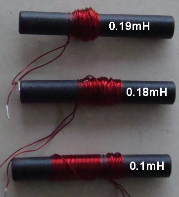
50 turns on 6mm x 40mm
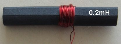
50 turns on 10mm x 40mm
Comparing the 0.19mH rod above with
the 0.2mH rod, you
can see the diameter of the rod made very little difference to
the value of inductance. The properties (quality) of the
magnetic material in the rod may have influenced the result.
An inductor has over 20 different uses. We are going to look at
some circuits using an
inductor.
The "Pi" FILTER
A Pi Filter consists of a
capacitor, an inductor (or a resistor) and finally another
capacitor.
Each of
the three components in this circuit reduces the ripple.
The amount of reduction depends on the value of each component.
A Pi Filter consists of: capacitor -
inductor - capacitor
It can also use:
capacitor - resistor- capacitor but a
larger voltage-drop will appear across the resistor.
The two capacitors (electrolytics): To understand how a capacitor works, you will have to look on
the internet "WALKING ON CUSTARD."
If you have a swimming pool filled with custard, you can run
over the surface and not fall in because the custard resists
being "hammered" by your feet. But if you slow down, you will
fall in.
That's how a capacitor works. When a voltage is
connected to a capacitor, it charges. If the voltage rises and
falls a small amount, the capacitor charges and discharges and
it takes time to charge and discharge. This slows down the time
the voltage can rise to its original value and it only gets to
charge a small amount before the voltage starts to fall again.
That's why the voltage rises and falls LESS than before. This
covers both capacitors.
Now we come to the inductor.
We know an inductor allows a steady voltage to pass through
without any change.
The voltage being filtered by this circuit consists of a steady
voltage with an AC component.
Ripple before Pi Filter
Ripple after Pi Filter
The diagram (graph) shows a voltage with a
ripple. The height of the "squiggle" is the amplitude of the
ripple. The arrows show the amplitude of the ripple. This ripple
is shown on the graph at a height from the "time" line. The time
line is also the 0v line and the distance between this line and
the ripple is the approximate DC component of the voltage.
The ripple after the Pi Filter will be very small as shown in
the second graph.
The steady voltage is called the DC component and this is not
altered by any of the three components in this filter.
It is the ripple (the AC component) that produces the expanding and
collapsing magnetic flux and when this ripple enters the
inductor it produces magnetic flux and this flux cuts all the
other turns to produce a voltage in the opposite direction.
This magnetic flux absorbs some of the energy contained in the
voltage and this reduces the height of the peak.
This reduces the peak portion of the ripple.
When the ripple drops to a lower value, a point is reached where
it cannot produce any flux and the flux stored in the core of
the inductor starts to collapse and produces a voltage in the
turns that increases the voltage flowing through the inductor
and thus the emerging voltage is slightly higher than the
original lowest value.
This increases the trough portion of the ripple.
In other words it "smoothes out" the peaks (highest
points) and troughs (lowest
points) by taking some of the voltage from the peak and adding
it to the lowest value via the energy in the magnetic flux.
This type of filter is very effective in reducing ripple, but it
is large compared to other forms of filters and the inductors
are expensive.
The INDUCTOR AS A SEPARATOR

Finally we have the inductor as a
SEPARATOR.
When an inductor is used in a circuit as shown above, it is
commonly called a CHOKE. This is really to emphasize the fact
that the signal does not pass through the inductor - in this
circuit.
It allows DC to pass (called the current in the circuit) but prevents AC
(called the signal in the circuit).
The inductor has a very small resistance and it allows current
to flow through it so the transistor stage works very
successfully.
The transistor is amplifying a signal and the signal emerges
from the collector in the first circuit and the emitter in the
second circuit.
If the inductor was a resistor of very small resistance, the
transistor would have to be turned on via large amount of base
current to achieve the bottom part of the waveform.
If the resistor is a large value, the transistor will not get
sufficient base current to produce a waveform. This is because
the collector voltage will drop very quickly and rob the base
from getting a voltage and current - the transistor will not get
turned ON and only the top of the waveform will be produced.
However the inductor has a very small resistance and it allows current
to flow through it so the transistor stage works very
successfully.
Here's how it works:
Normally, when the transistor turns ON, and the load is a
resistor, the resistance across the collector-emitter terminals
decreases and the current increases.
The increasing current through the load resistor produces a high
voltage-drop and this is how the lower part of the waveform is
generated.
When the load-resistor is replaced by an inductor, the
transistor turns on more and a higher current flows through the
inductor.
This produces more magnetic flux and a higher voltage is
produced by the inductor and this voltage lowers the voltage on
the collector.
In other words, a voltage is produced across the inductor, just
like a voltage is produced across a load resistor.
In both cases VOLTAGES are produced due to the current flowing, but the
inductor produces the voltage due to magnetic flux and the
resistor produces voltage due to Ohms Law.
What is the advantage of the inductor?
It takes less "effort" for the transistor to turn ON fully.
The inductor finds it very easy to produce a voltage that
"pushes" the collector away from the positive rail and this is
how the waveform is produced. It may even be responsible for
producing a larger waveform - depending on the circuit.
The inductor also has a "smoothness" about how it delivers the
voltage and this helps to produce a clean waveform.
In some circuits it improves the performance enormously.
Here is an animation of an inductor and transistor.
The transistor is turned ON more and more via the base.
This makes more current flow through the collector-emitter
terminals and we have shown this by the transistor getting
smaller and smaller.
This causes more current to flow through the inductor and the
increased current makes more flux.
The additional flux cuts all the turns of the coil and creates a
voltage in each turn that is opposite to the applied voltage and
a negative voltage appears on the lower lead of the inductor.
This puts a lower voltage on the collector and it is easier for
the transistor to turn ON harder.
Increasing the current into the base does not turn the
transistor ON an equal amount because the gain of the transistor
reduces as it gets turned ON more and more.
This causes the inductor to produce a varying output voltage and
the result is a waveform that is curved, similar to a sinewave.
The main point to understand is this:
The inductor makes it easier for the transistor to produce a
waveform and it improves the shape of the waveform.
2 CIRCUITS
Here are 2 circuits using the features of an inductor
we have mentioned above.
Here's the feature:
When an alternating signal is presented to one of the terminals
of an inductor, it produces a voltage equal to the
incoming voltage.
The signal we are talking about comes from the collector and
into the emitter via the 4p.
The inductor allows the signal from the
collector to pass to the top of the inductor via the 4p
capacitor and then into the emitter of the transistor.
The inductor allows the signal to rise and fall very easily and
this makes the voltage on the emitter rise and fall.
It is not easy making the emitter rise and fall and that is
another topic for discussion.
The base is firmly fixed via the 1u and when the emitter rises
and falls, the collector-emitter current rises and falls and
this produces the waveform in the 2.5 turn coil.
The bottom of the inductor is held firm via the 2n2 and the 560R
is a current-limiting resistor to only allow a small current to
flow in the circuit. If too much current flows, the transistor
gets swamped and overheats.
The inductor does two things. It allows the signal to pass from
the 4p to the emitter and it has a very low resistance so that
only a very small DC voltage appears across it. We have already
created a large voltage across the 560R and we don't have any
more voltage available, otherwise the voltage for the transistor
will be so small that the output waveform from the transistor
will be very small. The inclusion of the inductor and the 2n2
allows the transistor to produce a large output. It is really
only a few millivolts but it is amplifying the microvolts from
the air.
The inductor can be replaced with a resistor and two things will
happen.
Some of the signal from the 4p will be lost in the resistor and
a voltage will appear across the resistor and this will reduce
the output amplitude of the stage.
The value of the inductor is quite critical and it consists of
about 70 turns.
It improves the sensitivity of the circuit about 25%. A 60 turn
or 80 turn coil will give very poor results - it must be 70
turns for this particular circuit. The actual number of turns
depends on the frequency and can only really be determined by
experimentation.
.gif)
This circuit uses an inductor at the front-end to improve the
sensitivity.
It looks like the coil is a short-circuit to the signal, but it
forms a very simple parallel circuit with the 470p that collects
all the signals and uses the energy to produce some signals with
a higher amplitude.
This makes the circuit much more sensitive.
MANY TYPES OF INDUCTORS
There are thousands of different inductors on the market and
many more that have been made especially for a particular
application.
You cannot look at an inductor and work out its features.
Here's why:
An inductor has a value called its inductance and this is
usually marked via colour bands or written on the component. You
can measure this value in an INDUCTANCE METER. The meter sends a
pulse through the coil and measures result. But this is not a
"real circuit" evaluation. The inductor may react differently in
an actual circuit.
And there is another "hidden" value and this is its ability to
work at high frequencies. This feature depends on the type of
material used in the core. Air cores work to the highest
frequency.
The "Quality Factor of air is "1." Some materials have a "Quality
Factor of 100 or more and this means the coil is one hundred times
better than and air cored inductor.
Basically the Quality Factor means the inductor will produce a
back voltage 100 times greater than the supply voltage during a
particular test.
As the frequency of testing increases, the back voltage
decreases and at some point the voltage is the same as the input
voltage. This becomes the FT
of the material and it is no better than an air inductor.
The Quality Factor is often shortened to "Q."
Another factor that you have to be aware of is CURRENT
CAPABILITY.
One inductor can be wound with fine wire and have a high
resistance. Another inductor can be wound with thicker wire and
have the same inductance.
But the second inductor will not work in the same circuit
because the circuit is sensitive to the value of resistance.
In addition, inductors can have different "Q" values. Some
inductors are called "High-Q" inductors and these are suitable
for connecting across a capacitor to make a circuit called a
RESONANT CIRCUIT that produces a high voltage at a particular
frequency. It can also be called a TANK CIRCUIT when used in
Radio Frequency circuits.
HOW THE INDUCTOR WORKS
Here is a very simple way of explaining how the
INDUCTOR works. An INDUCTOR is simply a coil of wire on a
cardboard tube or wound on a metal core.
It is an electrical component but suppose we explain it as a
mechanical item.
Suppose we connect one end to a wall and turn it into a lever.
If we lift the lever, the lever reacts by lifting itself at the
same time. This makes it very easy to lift the lever.
This is how an inductor reacts to a rising voltage. If one end
of the inductor is tied to the wall, the voltage on the other
end rises at the same rate as the voltage you are applying. This
makes it very easy for the incoming voltage to rise.
If we replace the inductor with a resistor, it is like using a
lever made out of a thick piece of rubber. To raise the lever we
need to stretch the rubber and this is hard to do. The rubber
does not assist the incoming voltage and tends to work against
it.
Basically, a waveform trying to enter an inductor will have a
higher amplitude than the same waveform trying to enter a
resistor. The inductor will be producing a back-voltage that
will help the waveform because it will not allow as much current
to enter the inductor and this will not reduce the amplitude as
much as the resistor shown in the second diagram.
27MHz receiver
Now that we have explained how an inductor works, we can explain
the 33uH in the circuit above.
The circuit operates at 27MHz and the first transistor is
actually oscillating all the time, even though the circuit is a
receiver.
This is the clever part of how this type of circuit works.
The fist transistor is oscillating at a very low level and it is
sending out a signal on the receiving antenna.
When it picks up a signal with exactly the same frequency, the
two signals interfere with each other and the transistor takes
more current and less current at a much lower frequency called
the audio frequency.
This clever idea has been introduced because it is much easier
to control an oscillator that is already oscillating that try to
start up an oscillator circuit.
Now we come to the purpose of the 33uH.
The first thing to remember is this: A capacitor has a very big
effect on blocking or passing a frequency that is a HIGH
FREQUENCY. It will either block or pass the frequency, depending
on where the capacitor is located in the circuit.
And the same thing applies to an INDUCTOR. Its effectiveness
will be very high when the frequency s very HIGH.
That's why the value of a capacitor or inductor can be quite
small. Even a low value will have a noticeable effect.
In the circuit above, the 4n7 will have an effective resistance
of less than 2 ohms at 27MHz, so the bottom lead of the 33uH
will be effectively connected to the 0v rail, as far as the
transistor is concerned.
Now we come to the transistor. There are two ways to turn ON a
transistor. One is to keep the emitter fixed and increase the
voltage on the base and the other is to keep the base fixed and
reduce the voltage on the emitter.
We have kept the base fixed. The 33n on the base prevents the
base moving.
This means, to turn ON the transistor, we must reduce the
voltage on the emitter.
As mentioned above, the transistor is oscillating all the time
at 27MHz. This frequency is determined by the top 12 turn coil
and the 18p capacitor. These two components form a parallel
tuned circuit and the transistor is initially turned on by the
biasing components and the 390k on the base.
The tuned circuit creates a sinewave and during the production
of the complete cycle of the sinewave the transistor is turned
on and off.
The tuned circuit does this by delivering a pulse to the base
via the 33p capacitor and when a negative pulse is delivered to
the emitter via the capacitor, the transistor is turned ON more.
When a positive pulse is delivered, the transistor is turned OFF
more.
But what we want to emphasize in this discussion is the action
of the 33uH inductor. When the pulse is delivered by the
33p, the inductor "meets" this pulse (amplitude) and produces a
voltage of equal amplitude and this has the effect of not
reducing the amplitude. This means the full amplitude can be
applied to the emitter where it has the greatest effect on
either increasing or reducing the voltage.
If the inductor is replaced with a resistor, some of the energy
from the pulse will be absorbed by the resistor and the
sensitivity of the circuit will be reduced.
In fact, the impedance of the inductor is so critical that a few
turns more or less will reduce the performance by 10% or more.
THE RESONANT CIRCUIT - also called the TANK CIRCUIT
The Capacitor is classified as a PASSIVE COMPONENT because it
does not amplify.
The Inductor is classified as a PASSIVE COMPONENT because it
does not amplify.
But when these two components are connected across each other,
an amazing thing happens.
This amazing thing was detected in the early days when
scientists were demonstrating coils and capacitors and creating
sparks with batteries and wires.
When the coil and capacitor were placed in parallel, the sparks
increased in size and after further experimenting the scientist
found the circuit worked best at a particular frequency.
This was years before radio and the scientists though the
circuit stored energy and released it at a particular frequency.
When radio transmission came along, this circuit was used to
increase the output on a particular frequency and the name TANK
CIRCUIT was given to the combination.
The diagram above shows a TANK CIRCUIT - A RESONANT CIRCUIT
that oscillates at a particular frequency, determined by the
value of C and L (spoken as L and C).
Not only does it oscillate and produce a beautiful sinewave
output, but the wave is TWICE the voltage of the supply.
To see how it works, we very briefly connect a voltage.
The capacitor charges to full rail voltage and the inductor sees
this voltage and produces a back voltage that opposes the
voltage and it produces very little magnetic flux.
The supply is now removed.
The capacitor now delivers its energy to the inductor and the
inductor produces a back voltage. If the energy tries to be
delivered too fast, the back voltage increases and slows down
the process.
This is how the shape of the waveform is produced.
A point is reached where the energy from the capacitor is not
enough to maintain the flux in the inductor and it starts to
collapse and produce a voltage in the opposite direction.
This charges the capacitor IN THE OPPOSITE DIRECTION and that's
how the waveform below the bottom rail is generated.
This action will occur a few more times, but each time the
amplitude of the sinewave gets smaller.
When these two components are connected to a circuit, they send
out a signal so they are injected with a small amount of energy
to maintain the exact same frequency of operation.
That's why this circuit is called a TUNED CIRCUIT, because it is
TUNED or SET or ADJUSTED to operate at a particular frequency.
It is these two components that set the frequency. The
transistor driving the two components simply injects a small
amount of energy at the appropriate time to keep them
OSCILLATING.
The end result is the waveform is TWICE the voltage of the
supply. In other words, the circuit has amplified the voltage of
the supply.
This is what they have done:
They have turned pulses of energy from a transistor into a very
smooth sinewave.
They have "controlled" the transistor and set the frequency of
operation.
They have produced a sinewave that is double the voltage of the
supply.
HOW THE TANK CIRCUIT WORKS
We start with a fully charged capacitor and this voltage is
passed to the inductor.
This voltage allows a current to flow though the coils of the
inductor and each turn produces magnetic flux that cuts all the
other turns of the coil. Each turn is producing "magnetism" and
it is seeing magnetic lines of force from all the other turns at
the same time as it is producing magnetic flux and these
(outgoing lines) lines are cutting the other turns and producing
a microscopic voltage in each turn that has an opposite polarity
to the voltage being applied to the coil. Magnetic flux that
enters a turn produces a voltage that is opposite to the applied
voltage.
So we have a "back-voltage" produced by each turn.
The end result is this: The applied voltage may be 10v but the
BACK-VOLTAGE can be as high as 99% and thus only 0.1v is
effectively entering the coil and this is producing very little
magnetic lines. However we keep applying the voltage and
gradually the small effective forward voltage will increase the magnetic
field of the coil and at the same time the voltage
from the capacitor is gradually decreasing.
It comes to a point where the voltage from the capacitor cannot
produce expanding magnetism (called EXPANDING FLUX) that is INCREASING and it has totally run out
of energy. The inductor will have lots of flux but this flux is
called stationary flux and stationary flux does not produce a
back voltage in the turns. Up to this point all the energy from
the capacitor has been converted to magnetic flux.
Everything now stops and the magnetism produced by the inductor
starts to "fall back into the inductor" to produce a voltage in
the turns that has an opposite polarity.
This voltage emerges from the inductor to charge the
capacitor in the opposite direction. There is a small loss in this cycle but the capacitor
will charge to almost its original voltage (but opposite
polarity) when all the magnetic flux has collapsed (disappeared
- converted to a voltage in the capacitor).
One of the requirements of an LC oscillator is the fact that the
energy in the capacitor must match the energy required by the
inductor. If the energy in the capacitor is more than the
inductor will absorb, the extra energy will simply be converted
to magnetic flux that will not be returned to the circuit in the
next half-cycle. This does not really matter if you are
injecting energy into the circuit on each cycle but it is simply
wasted energy.
Another point to note is this: If you are driving the circuit
with say a 3v supply, you may be able to produce 2v across the LC
circuit and then turn off the supply at the correct part of the
cycle. It will then produce a 2v waveform and complete a
second 2v waveform that is in the opposite direction, making the
combined output equal o 4v.
The third point to note is this: The circuit is given a pulse of
energy for about half a cycle to charge the capacitor and then it
is REMOVED from the circuit and the two components perform the
remaining half cycle.
Generally there is a "pick-off point" where the
amplitude of the
circuit (the energy of the circuit) is passed via a capacitor to another stage that detects
the frequency. This removes quite a bit of the energy but it
must not change the timing of the circuit, otherwise the
frequency of operation will reduced.
The way a capacitor charges and the way an inductor accepts
energy (when they are in combination) produces a very nice sine
wave. This is only true if the circuit is not loaded and not
injected with too much energy.
Here is one more amazing fact about an inductor. The
energy from a collapsing field of an inductor is simply called
ENERGY. It will be released as a very high voltage with a very
small current or as a very low voltage with high current.
The inductor does not decide. It is the load applied to the
inductor that decides the voltage and through Ohm's Law, the
current is delivered.
MORE ON: HOW THE TANK CIRCUIT WORKS
An "in-depth" description of how the Tank Circuit
delivers the energy from the capacitor to the coil (inductor)
and then back to the capacitor.
The "secret" of its operation has never been described before
and all discussions have glossed-over "how and when and why" the
capacitor gets fully discharged before the cycle starts again.
Suppose the capacitor is charged and is placed across the
inductor. Current will flow into the inductor and produce
magnetic lines of force in the core that will cut all the other
turns and produce a voltage in these turns that is opposite to
the incoming voltage. This means the incoming voltage will see a
voltage produced by the inductor that will be as high as 99% of
the incoming voltage. This means the incoming voltage will
appear as a very small voltage and it will increase the flux
lines very slowly.
The capacitor will keep supplying current but since the voltage
across it is reducing, the current will be reducing and thus the
flux will be expanding at a reduced rate. The back voltage
produced by the expanding flux depends on the rate of expansion
and since this expansion is getting less, the back voltage is
reducing.
The amazing thing is this: as the voltage of the capacitor
decreases, the back voltage decreases and the current increases.
I can explain it this way.
Suppose you put a 9v battery across the coil, after a short time
the flux will be a maximum but it will not be expanding flux and
inductor will produce the maximum flux and take the maximum
current.
When the capacitor is almost fully discharged, the current will
be a maximum and because the flux is not expanding, there will
be no back voltage.
So a point comes when the capacitor has no voltage across it and
the inductor produces no voltage.
This is the secret to how the oscillator works.
Because the inductor has a very small resistance, it only takes
a very small voltage to deliver a very high current and produce
a very large amount of magnetic flux. But eventually this small
voltage cannot maintain the flux and all the voltage and
current-capability is taken from the capacitor.
At this point in the cycle, the flux cannot be maintained and it
starts to collapse. As it collapses, it can only produce a
certain amount of current and this current charges the
capacitor. In other words the capacitor controls the rate of
collapse of the inductor and the voltage across the capacitor
gradually increases.
In actual fact, the inductor "can and will" produce a very large
voltage during a collapse if nothing is connected to it and this
is called a fly-back voltage.
But since a capacitor is connected, the voltage can only rise as
the inductor controls this part of the cycle.
The capacitor want all the energy as fast as possible but as the
inductor generates a voltage, a current is also produced during
the charging process and this current produces a back-voltage in
the turns that reduces the voltage to the capacitor. This is
what makes the charging of the capacitor SO SLOW.
It rises until the flux has almost fully collapsed and even
at this point the collapsing flux is able to produce a voltage
much higher than the voltage across the capacitor and that's why
it can keep charging the capacitor right up to the point when
the flux has almost completely collapsed.
That's why the capacitor gets charged to almost the original
voltage.
Even the tiniest amount of flux will produce a charging voltage.
But eventually the flux is zero and the voltage across the
capacitor sees the inductor as a very small resistance and it
starts to deliver a current. This current produces magnetic flux
in all the turns of the winding and each turn produces a back
voltage so that the actual magnetizing voltage is very small and
thus only a very small current flows to create the second cycle.
THE SECRET
Here's the reason why the capacitor is able to deliver all
its energy to the coil:
As the voltage across the capacitor decreases, the coil can only
produce a back voltage that is slightly less than the capacitor
voltage. That's why the energy keeps flowing from the capacitor
to the inductor. It is only when the capacitor cannot deliver
any more current, that the circuit starts to change direction.
Just before this occurs, the voltage of the capacitor can be
very small because the resistance of the inductor comes into
play since the back-voltage is very small and it is the
back-voltage that turns the resistance of the coil into an
inductance. Now we have a very small capacitance voltage being
able to deliver a high current into a small resistance to
maintain the magnetic field.
Only when this voltage finally reduces to almost zero, does the
circuit start to change direction.
Now, going back in the other direction, why is the inductor able
to keep charging the capacitor when it is nearly out of magnetic
flux?
The reason is this. If the capacitor was not connected,
the inductor would be able to produce a very high voltage when
the magnetic field is collapsing because the size of the
back-voltage depends on the speed of the collapsing field and
the current in the winding, producing an opposing voltage. With
no load, this back voltage is not present and the output voltage
is enormous.. Even
when the inductor is almost out of flux, it can produce a very
high voltage when nothing is connected to it. That is: when no
capacitor is connected, it will collapse very fast and produce a
very high voltage.
So, it is the capacitor that is controlling this voltage, BUT it
is always slightly higher than the voltage across the capacitor
so the charging keeps occurring until the inductor is finally
out of flux.
Don't forget, when the magnetic field of the inductor is
collapsing, the voltage it is producing is in the opposite
direction to the original voltage.
This means the capacitor gets charged in the opposite direction.
In the diagram above, the top rail is the supply rail and the
bottom rail is connected to a transistor.
If we connect a multimeter or digital CRO to the transistor, we
will see the voltage reduces lower than rail voltage during half
the cycle and then becomes higher than rail voltage during the
second half of the cycle.
This means the effective voltage at this point is TWICE RAIL
VOLTAGE. The Tank Circuit can double the supply voltage !!
oooooooooooooooooooo00000000000000000000oooooooooooo
8R
SPEAKER Vs 50R SPEAKER
A speaker is an inductor.
Most of the speakers used in
transistor radios have an impedance (resistance) of 8R
for the VOICE COIL. This has been chosen because it is
very easy and cheap to produce. The wire in the coil is
also quite thick and robust.
But it is interesting to note that speakers with a high
resistance voice coil will produce an equal volume and
require less driving current. This applies to 33R
speakers as well as 50R speakers.
The reason is this:
Moving the cone requires a certain amount of flux and
this can be produced by a small number of turns and a
high current or a large number of turns and a low
current.
The flux is a product of turns x current and this is
called AMP-TURNS. In other words, AMPS x TURNS (number
of turns in the coil of wire).
A speaker is a LINEAR ACTUATOR and the principle of
AMP-TURNS can be applied when designing one of these
devices.
Other, closely related devices include the ELECTROMAGNET
- for picking up scrap steel, DOOR RELEASE - for
unlocking a door, LINEAR MOTOR - for high speed trains
and levitation, and the electric motor - such as the 3-pole
motor (or 5 pole etc).
And there are dozens of other devices that use a coil of
wire that has INDUCTANCE, for an application that uses
(makes use of)
the magnetic flux produced.
Sometimes the inductance comes into the calculation
because it limits the frequency at which the device will
operate.
This topic can become very complicated.
The simplest of all electrical devices - a coil of wire
- has the largest number of applications in electrical
circuits and electronic circuits - and
requires some of the most complex theory to understand.
HIGH-VOLTAGE - FLYBACK
All the circuits
above are "controlled." By this we mean the waveform is
rising and falling at a known rate.
In these conditions, the output from the inductor will
be slightly less than than the incoming voltage.
If the voltage was the same, there would be no resulting
input voltage and no current would flow and no flux
would be produced.
But
if
the incoming voltage is turned off instantly, the
magnetic flux collapses very quickly and the voltage
produced by the inductor can be 10 times to 1,000 times
greater than the supply.
This is called a FLYBACK VOLTAGE and there is a whole
range of circuits using this feature.
That's why you have to "see" a circuit working to be
able to work out what is happening.
RECAPPING
A coil of wire on a former is called a SOLENOID or
ELECTROMAGNET or INDUCTOR. It can also be called a
CHOKE.
When there are two separate windings it is called a
TRANSFORMER. (or the two winding can be joined in
the middle and it is still called a transformer - an
AUTO TRANSFORMER).
A FORMER is a cardboard or plastic tube and it can be
AIR CORED - nothing in the middle.
A metal rod in the middle is called a CORE. It can be a
nail, brass screw, iron rod, ferrite rod, ferrite core, steel, or thin
sheets called LAMINATIONS.
All these materials have a different effect and different
result on the inductance of the coil and some of the
results will surprise you.
When a voltage is applied to an inductor, current starts
to flow and this produces magnetic flux that cuts all
the turns of the coil to produce a BACK VOLTAGE called
BACK EMF.
This "pushes against" the incoming voltage and the
result is only a small incoming voltage is available.
This small voltage only allows a small current to flow
and that's why it takes a long time (microseconds) to
get the full current to flow.
When the full current flows, the back voltage is not
produced but the inductor is producing the maximum
magnet flux.
When the supply is turned OFF, this magnetic flux
collapses and cuts all the turns of the coil and because
there is nothing opposing this voltage, and the
resulting voltage is ENORMOUS.
It can be 10 times to 1,000 times larger than the supply
and this is the "zap" you get when you hold the ends of
the coil in your fingers.
This voltage has a polarity that is OPPOSITE to the voltage
of the supply.
The INDUCTANCE of a coil is measured in Henries, milli-Henries
or micro-Henries.
The colour bands on an inductor are in microHenries.
The numbers on a surface mount inductor are micro-Henries.
The numbers on other inductors are micro-Henries. It is
always microHenries.
Such as 104 = 100,000 micro-henries = 10 milli-Henries.
See
our other article on the INDUCTOR.
Here is a colour code calculator from the web:
http://www.electronics2000.co.uk/calc/inductor-code-calculator.php
Here is a colour code calculator for Resistors,
Inductors and other things:
If you found this calculator useful why not download Electronics
Assistant?

-
All the online calculators and more in a stand-alone application
-
Converts Resistor & Inductor colour codes, calculates LED series
resistors, capacitance units, series / parallel resistors &
capacitors, frequency, reactance & more
-
Calculation of nearest preferred resistor values with a choice of 5
series from E12 to E192
-
Print & save calculation results
MAKING YOUR OWN INDUCTOR
Making an inductor is very complex and using a formula will only
cause frustration.
Here is the only way to design your own inductor:
Go to eBay (and also try electronic parts suppliers) and buy a
whole range of inductors and test them in the circuit you are
designing.
The material of the core as well as the current capability of
the inductor is
also important - so the size of the wire may be one of the
things you have to consider.
If it works perfectly, use it. Make sure it does not get hot.
If you want to change the inductance slightly, you can remove
the heatshrink and remove some of the turns.
If you want to know the value of inductance, buy an inductance
tester from eBay for $15.00.
It tests resistors, capacitors, inductors and electrolytics.
You can increase the inductance by adding turns, but it is much
easier to remove turns from a larger inductance.
Only remove a few turns at a time.
When you have finished you can count the turns but you must get
the same core to achieve the same inductance.
SELF INDUCTANCE AND MUTUAL INDUCTANCE
These two terns
sound complex but they simply mean:
SELF INDUCTANCE refers to the inductance of a single coil with a
single winding. It can have one turn or a million turns. It just
has to be a winding with a single wire at the start and a single
wire at the end.
MUTUAL INDUCTANCE refers to an inductor with 2 windings (or 3 or
more) where one winding is being supplied with a waveform and
the magnetic flux is passing to the other winding and producing
a waveform. An example is a transformer. |