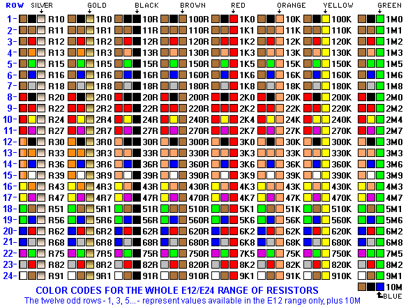
USING A
MULTIMETER
Analogue and digital
multimeters have either a rotary selector switch or push buttons
to select the appropriate function and range. Some Digital
Multimeters (DMMs) are auto ranging; they automatically select
the correct range of voltage, resistance, or current when doing
a test. However you need to select the function.
Before making any measurement you need to know what you are
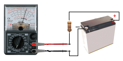
checking. If you are measuring voltage, select the AC range
(10v, 50v, 250v, or 1000v) or DC range (0.5v, 2.5v, 10v, 50v,
250v, or 1000v). If you are measuring resistance, select the
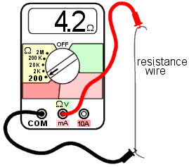
Ohms range (x1, x10, x100, x1k, x10k). If you are measuring
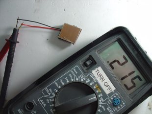
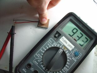
current, select the appropriate current range DCmA 0.5mA, 50mA,
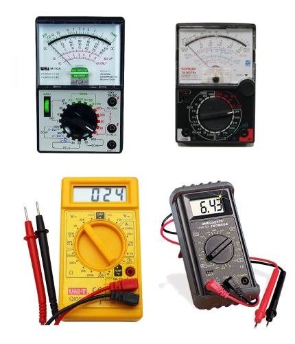
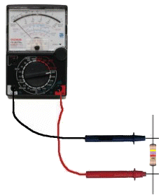
500mA, 10A. Every multimeter is different however the photo below
shows a low cost Analogue multimeter with the basic ranges.
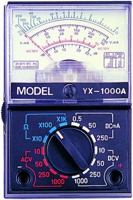
An ANALOGUE MULTIMETER
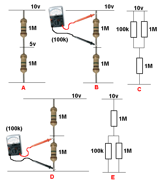
The most important
point to remember is this:
You must select a voltage or current range that is bigger or
HIGHER than the maximum expected value, so the needle does not
swing across the scale and hit the "end stop."
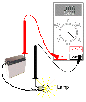
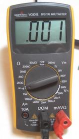
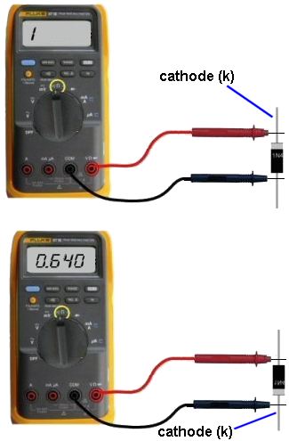
If you are using a DMM (Digital Multi Meter), the meter will
indicate if the voltage or current is higher than the selected
scale, by showing "OL" - this means "Overload." If you are
measuring resistance such as 1M on the x10 range the "OL" means
"Open Loop" and you will need to change the range. Some meters
show "1' on the display when the measurement is higher than the
display will indicate and some flash a set of digits to show
over-voltage or over-current. A "-1" indicates the leads should
be reversed for a "positive reading."
If it is an AUTO RANGING meter, it will automatically produce a
reading, otherwise the selector switch must be changed to
another range.
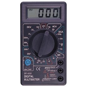
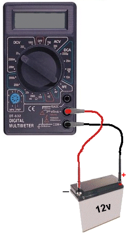
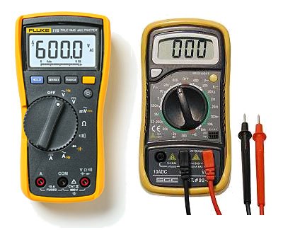
A typical DIGITAL Multimeter
The
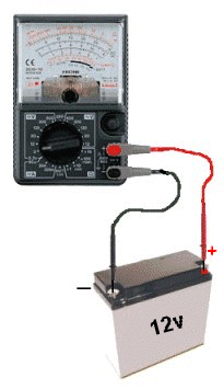
Common (negative) lead ALWAYS fits into
the "COM"
socket. The red lead fits into the
red socket for Voltage and Resistance.
Place the red lead (red banana plug)
into "A" (for HIGH CURRENT "Amps")
or mA,uA for LOW CURRENT.
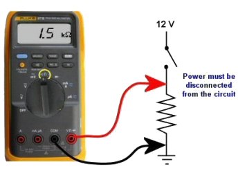
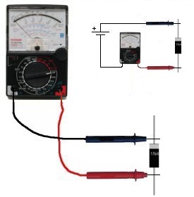
The black "test
lead" plugs into the socket marked "-" "Common", or "Com," and
the red "test lead" plugs into the meter socket marked "+" or "V-W-mA."
The third banana socket measures HIGH CURRENT and the positive
(red lead) plugs into this. You DO NOT move the negative "-"
lead at any time.
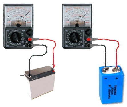
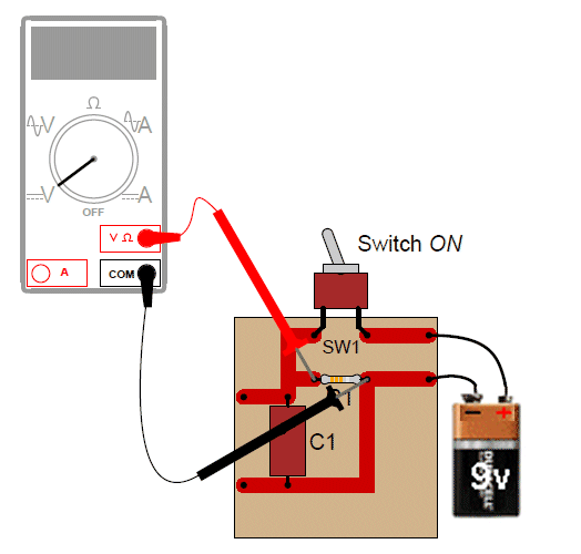
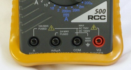
The following two photos show the test leads fitted to a digital
meter. The probes and plugs have "guards" surrounding the probe
tips and also the plugs so you can measure high voltages without
getting near the voltage-source.
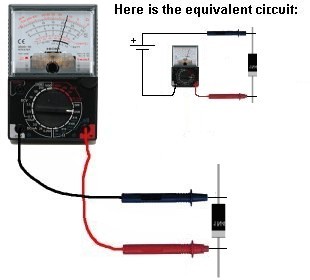
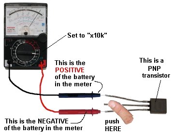
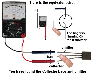
Analogue meters
have an "Ohms Adjustment" to allow for the change in voltage of
the battery inside the meter (as it gets old).
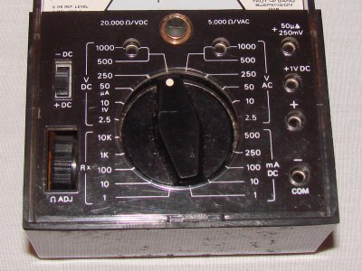
"Ohms Adjust" is
also called "ZERO SET"
The sensitivity of this meter is
20,000ohms/volt
on the DC ranges and 5k/v on the AC ranges
Before taking a
resistance reading (each time, for any of the Ohms scales) you
need to "ZERO SET" the scale, by touching the two probes
together and adjust the pot until the needle reads "0" (swings
FULL SCALE). If the pointer does not reach full scale, the
batteries need replacing. Digital multimeters do not need "zero
adjustment." |