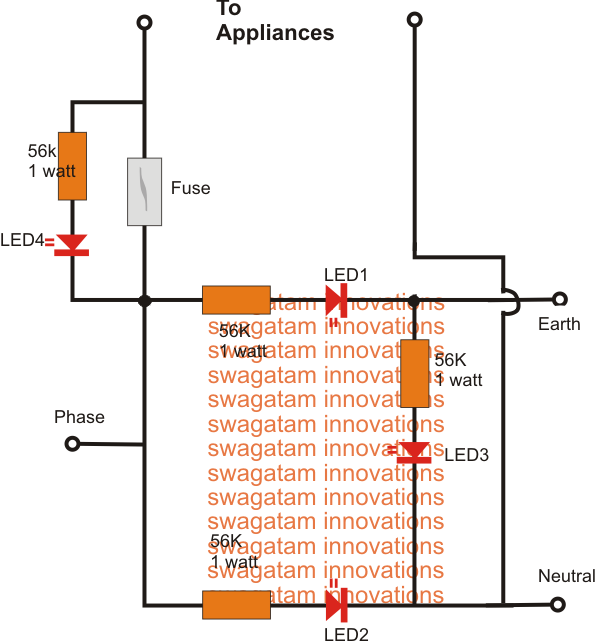
How can I connect a led to two outputs and it only illuminated when both outputs are HIGH?
SPOT
Page 1
Page 2
Page 3
Page 4
Page 5
Page 6
Page 7
Page 8
Page 9
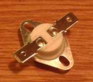
At the beginning, some readers thought it was a transistor; one thought it had a
positive or negative temperature co-efficient, a ceramic disc thermostat, a
resistive temperature thermostat, and many other obscure answers.
I’m an engineering student. My professor required me to make a 7-segment display
that start counting from 00-99 when hitting single switch. My professor only
asked for logic gates IC like 7400, 7402, 7404, 7408, 7432, 7486 or simple OR,
NOT, AND,
NAND, NOR, XOR, etc.
She also asked 555 timer for delays and used only the given IC. I already know
the Karnaugh map values from a-g, so the question is how to make a 7-segment
display from 00-99 with just single click on the switch with a delay from 555
timer?
This is a totally worthless assignment.
THE MISTAKES!
Page 22
Page 10
Page 11
Page 12
Page 13
Page 14
Page 15
Page 16
Page 17
Page 18
Page 19
Page 20
Page 21
Page 23
Page 24![]() Many readers have asked for more-complex projects.
Many readers have asked for more-complex projects.
I have already produced a number of fairly complex projects and they have
received very little interest.
The readership of every page is recorded in a file by
Histats and the 50 - 555
Circuits
chapter gets 500 visitors each day, whereas the Basic Electronics Course gets
less than 40.
The duration of each reader on a page is not recorded, however the mere fact
that a complex project gets just a few readers each day, shows the interest dwindles for anything complex.
A recent quiz on an electronics forum asked the readers to identify the
following:
The number of incorrect answers was surprising, even after many had correctly
identified the object.
It highlights the fact that many readers can supply an incorrect response
without first checking the details on the web.
![]()
Time at University is expensive and very limited. Every effort has to go into
producing the greatest outcome.
No-one has ever explained the real purpose for gaining a degree. The real reason
is to produce a student who can make an impression on companies who are looking
for new staff.
They are actually looking for those who will generate 2 to 5 times their salary.
Engaging a new member of staff is a commercial transaction and don't fool
yourself otherwise.
That's why they really want an "electronics wiz" with 5 to 20 years experience.
But these are hard to come-by and they have to resort to a "second-choice."
The only reason you invest in a University degree is to get your
"foot-in-the-door" without having 5 years experience in electronics.
If you think you know anything about electronics after a 5-year course, you are
fooling yourself.
You probably don't even know how much room is required between a tall and short
component to allow for wave soldering.
If you only complete 3 or 4 projects each year, the above task should be to
produce a 2-digit counting circuit using a microcontroller, with up-down feature
and a preset.
This is the type of counter used in packaging on production-lines.
I can understand using gates to produce a counter some 30 years ago, but times
have changed.
I have had a lot to do with "Professors" and they are still living in the 70's
and re-gurgitating concepts they learnt in the past.
Tell the "Professor" you are going to use a microcontroller and want help with
the debounce routine.
![]()
Here are the most-common 3 mistakes of ALL TIME:
I am trying to build a warning speedometer that will be capable of
driving an 8 ohm speaker and the speaker will sound at 60mph and the tone
increases and interrupted 10mph thereafter. It must also show the values in 2
seven segment display. In addition I cannot used programmable chips. Can anyone
please help me in my senior design project. I am struggling to build and design
it.
The circuit has lots of mistakes.
The
circuit can be simplified to this:
There is NO skill in producing a complex circuit.
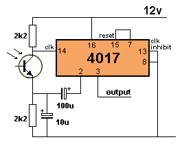
TOGGLE AN OUTPUT
The circuit can be simplified to this:
The 100u creates a delay so the chip can only be clocked every second.
Why does the LED take so long to come ON?? It should
come on immediately. There are no capacitors in the circuit to delay the
action. What is the purpose of the 1k across the power rails ??
It's an oscillator circuit illuminating a white LED from a 1.5v battery.
When one segment is illuminated, it will get about 15mA via the 220R resistor.
Apart from the absurdity of flashing a red LED from a 9v
battery, the discharge pin (pin 7) of a 7555 IC is not designed to pass a high
current.
The diode serve NO PURPOSE. The LED discharges the 10u very
quickly and the 330k charges it very slowly.
TL431 is possibly the WORST device you could use to detect
battery voltage as the voltage only has to rise a few millivolts and the device
changes state.
The complex circuit above can be simplified to:
This is a typical example of failing to search the web for a simple
circuit before launching into something complex. As I have said before,
there is no skill in producing something complex. Here is a circuit from a 1985 Indian book on LED circuits. I was
going to put it on the web, but it contained so many mistakes that it would
confuse many readers.
I could not see if the circuit above worked, so I turned it
around the correct way:
Build the circuit and see it it works. Use 470R for
R3 and R4 and 22k for R1 and R2. 47u for the
electrolytics.
From
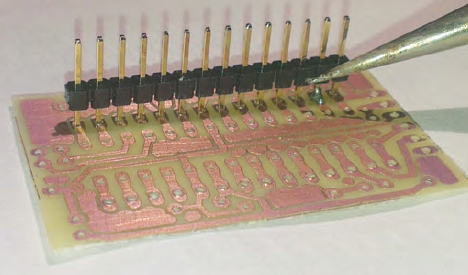
If any of my workers soldered jumpers like the photo above, they
would be sacked ON THE SPOT. There is one area we have not covered on our Talking Electronics
website. It is CLEVER DESIGNING. Here is the first answer:
Here is the third reply:
Here is the fourth reply:
As you can see, the answers get simpler and simpler. Some results have a
different effect on the load on the outputs and the quiescent current
consumption, so the simplest answer may not be the best.
Here is a discussion from a forum. I am doing this little project, is a solar charger for 2 AAA
Batteries 550maH. Here is the circuit:
The first reply, stated: This is entirely WRONG
Half the components in the AC section can be removed. The zener
diode and 1k are not needed as the LED can be across the supply from the 100n
and the power diode will discharge the 100n when it is across the LED with the
cathode to the 0v rail. RADIO
SHACK FINALLY DIES
He did not ask for samples or anything about the kit and this seemed strange.
This is a set of conversations taken from an electronics forum:
The reverse voltage on LEDs 1 and 2 will BLOW THEM UP!
Phase is also called "ACTIVE."
Here's a website with over 1,000 projects:
Here's some more mistakes from
1. I know nothing about electronics, I have hardly built a project, but I will
take an electronics course and become an ELECTRONICS ENGINEER!
You are fooling yourself if you think an electronics course will teach
you anything or everything about electronics. We see dozens of students on
forums asking for advice on a final electronics project.
Even after suggestions they can hardly interpret a circuit diagram or source the
components.
I have seen students emerge after a 3-year course, not being able to read a
resistor or solder a surface-mount component. But they can
read the load-line of a transistor - AND GET IT WRONG!
Students think the lecturer, the notes and text-book will turn them into an
engineer. I have not found one text book that is vaguely related to
understanding how to build and design the full range of the most-common building
blocks.
Ten of my most-basic question are not answered in any text book. How can you
possibly say a course will get you "into electronics?"
2.
I will buy a CRO (or other piece of test equipment) to solve my circuit
diagnosing problems.
This is a BIG MISTAKE. A Logic Analyser or Solid-State CRO will show all
sorts of wave shapes but it will not tell you the location of the fault or which
part of the graph is faulty. Sometimes it will lead you in the wrong direction!
It is only helpful in the hands of an EXPERT.
3.
With my "Master's Of Electronics" I will be able to design and build my
own projects.
There is absolutely no relationship between fulfilling the requirements
of a course and being able to design a successful project.
90% of students in their final years are just beginning to scrounge around and
look for a "FINAL YEAR PROJECT."
They are doing the wrong course.
I have 10 projects "on the go" at any one time and always waiting for 3 or 4
panels of PC boards to be made in China. One project sparks another and if you
are not deigning one project after another, you are in the wrong profession.
If you think you will "learn on the job," you will miss out on being employed.
Only 1 person in one-hundred is really employable in a profession (we are not
talking about counter-staff, or burger-flippers) and you need to be that 1%.
![]()
Spot the Mistakes
adds a new dimension to teaching electronics. It explains why certain
things cannot be done, (such as using a high-power transistor in an RF amplifier
to replace a small current device - the circuit will simply NOT drive the high
power transistor AT ALL).
We have already presented hundreds of circuits, shown how to test components,
provided the basics to circuit design, and
Spot the Mistakes
fills in the final elements.
All that is left is for you to build something.
I have 15 projects on the go at any one time and many of them are waiting for
the PC boards to come back from the manufacturers.
There are some very cheap manufacturers in China that cost less than $1.00 per
board but you have to wait 10 days for the post to deliver the parcel.
I have explained this in the article
PROTOTYPING BOARDS
and covered the use of MATRIX BOARDS and how to start designing your own board
with Protel software.
Electronics is one of the cheapest hobbies because you can re-use many of the
components in the next project and the cost of parts has come down a lot due to
eBay. You can buy everything on eBay and sometimes the postage is FREE.
You cannot compete with the Chinese.
They have copied the Western World to a TEE.
40 years ago, Philips and Germany were the leaders in component design.
The components from the US were UGLY. Fortunately China copied the European
designs and now we have the best components at the lowest prices.
But it's no-good "LOOKING" at the components. You have to involve yourself and
think of ideas. One idea generates another and after producing more than 1,000
projects, I have a whole list of ideas for the future.
You don't need a "CV" to get a job. Just write: " I have a box of 63 models and
projects to show you in the interview" and you will land the job.
![]()
There is a small group of readers who have read nearly all the pages in
this Spot The Mistakes section.
It is actually one of the MOST IMPORTANT sections you can read. You can learn 10
times faster from a faulty circuit than reading boring theory.
Here is an email received two days ago:
(the spelling and grammar have been corrected)
My name is Hariesh and I am from India. I love electronics and I am an
electronics enthusiastic who likes to build projects for my own use. The love
of electronics was always in my blood as it started from
my childhood. By profession I am a computer engineer. I previously searched
online for different circuits and I tried to build them, but many of
them did not work. A few weeks ago I come across your website and
found "spot the mistake page." The folder was so lengthy (almost 24 pages).
I have gone through all the pages and was really shocked to
see the mistakes and untested circuits. I don't know how to express my
thanks to you since the criticizer in you has revealed many mistakes
which will be useful for the people like me and it is really sad that
most of the circuits you have spotted have been tried by myself
and failed, without knowing that the circuit was just an idea and
are not really tested. There are many circuits which are useful to me but many people will
not point out the mistakes because they do not understand how the
circuits work. But you are
different from others. And off course I know that you may be disliked by
many authors who publish wrong circuits. I believe they don't know how to
deal criticism in a positive style and sports-man-like spirit. Imagine if nobody
was there to criticize literature. How would we get great works like Leo Tolstoy?
And when it comes to electronics, you are the number one
who criticizes to get junk off the web.
The web is wonderful. It can inform everyone in the world to the latest
technologies, no matter where they live. Everything is FREE on the web and
you just have to pay for time at an internet cafe to download.
80 years ago this was called "School of the Air" where students had PEDAL RADIOS
radios to listen to classes (in the outback of Australia). Hobbyists in 3rd
world countries can now study and keep up with electronics and this will allow
them to generate a skill to assist them in a career. Talking Electronics
gets hundreds of emails from readers doing just that. Eventually they will get
into the service and supply of electronics to help those in remote areas.
As I have said before, the web will be the eventual TEACHER of the world.
![]()
Where has he been for the
last 3 years of his "MASTERS
OF ELECTRONICS" course?
Either the course is poor quality, or the Lecturer is incompetent or the student
is dong the WRONG COURSE.
With the introduction of the web there is absolutely no excuse for not referring
to it on a daily basis and looking through the projects and circuits designed by
others.
40 years ago there was hardly a source of circuits and major text books were
expensive.
Everything is now FREE and if you expect to be successful in electronic design,
it is too late to ask for help on a simple project like this, in your final
course-year.
In fact we don't people like this, pulling-down the profession. Fortunately it
is mainly reserved for people who understand electronics and anyone "bumbling
along the bottom" will quickly exit the field.
The lesson to be learnt is this: Don't think you can "fool your way" through a
course. You have to be 100% successful to be a design engineer.
You can be a solicitor and never win a court-case. Or build a bridge and hope it
will never fall down.
But an electronic device will not work if even with the slightest mistake.
That's why you need to pay attention to detail.
![]()
CAR INTERIOR LIGHT FADER
The circuit fades the
interior light after the door has been closed: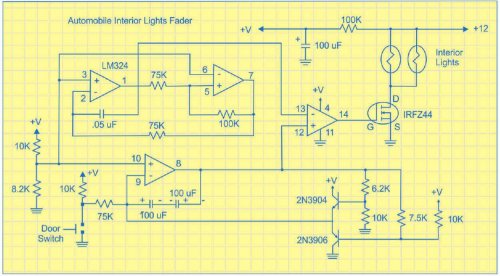
The 100k from the 12v supply supplies power to the op-amps. The op amp will
reduce this voltage to almost zero. The 10k and 8k2 will also reduce the voltage
across the op-amp. The circuit DOES NOT WORK. 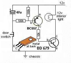
Before you waste time designing ANYTHING, look on the web for circuits that have
already bee designed and tested. ![]()
The circuit toggles the
output to turn the lamp on an off via a laser pointer.
![]()
LED and SWITCH 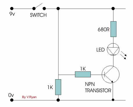
Two mistakes that should not be in a simple demonstration circuit. ![]()
KEYCHAIN LIGHT
Here's another faulty circuit from ELECTRONICS FOR YOU Magazine: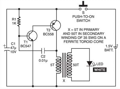
Why does the transformer have 50 turns on the secondary?
For each 5 turns on the transformer, 1.5v will be produced. The White LED only
needs 3.6v.
If the supply drops to 0.9v, each 5 turns will produce about 0.65v after the
collector-emitter drop of the PNP transistor and you only need about 30 turns.
There is no current-limiting resistor in the path made up of the emitter-base of
the PNP transistor and collector-emitter of the NPN transistor. When both these
transistors are turned ON the voltage drop will try to fall as low as .065v +
0.25v due to the junction-voltages and this will cause a very high current to
flow.
This is wasted current and could be more than the current flowing through the
transformer to illuminate the LED. ![]()
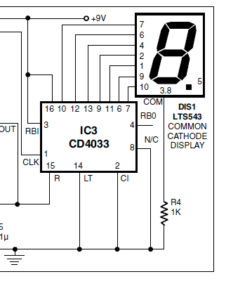
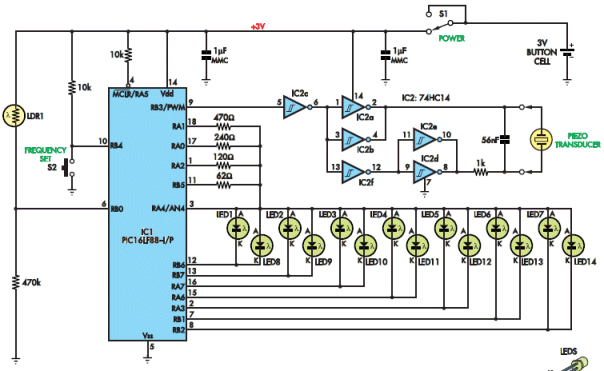
7-SEGMENT DISPLAY
Here's another badly-designed circuit from ELECTRONICS FOR YOU Magazine: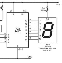
When 2 segments are illuminated, they will get 7.5mA each.
But when 7 segments are illuminated, they will get less than 2.2mA each and the
whole display will be very dull.
This will be obvious when you build the circuit and it shows the circuit has
never been constructed !!![]()
7555 FLASHER
Here's another badly-designed circuit from ELECTRONICS FOR YOU Magazine: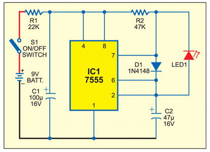
The 47u charges to about 6v and its energy is passed directly to the LED when
pin 7 goes LOW. This produces a bright flash. But pin 7 is not designed to do
this. ![]()
CD4093 FLASHER
Here's another badly-designed circuit from ELECTRONICS FOR YOU Magazine: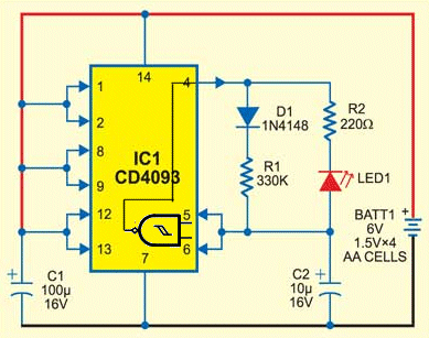
![]()
TL431
Here's another badly-designed circuit from ELECTRONICS FOR YOU Magazine: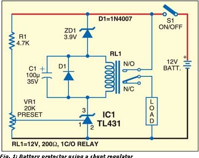
You need a wide distance between the circuit turning ON and OF and then ON again
because the voltage of a battery will rise as much a 0.6v when the load is
removed.
This is called the HYSTERESIS GAP.
This circuit will switch ON-OFF-ON-OFF. Some circuits will work due to the 3v9
zener only allowing the relay to see 8.5v when the battery is fully charged. But
some 12v relays will still pull in at 6-7v.
![]()
40kHz Transmitter
Here's another badly-designed circuit from ELECTRONICS FOR YOU Magazine: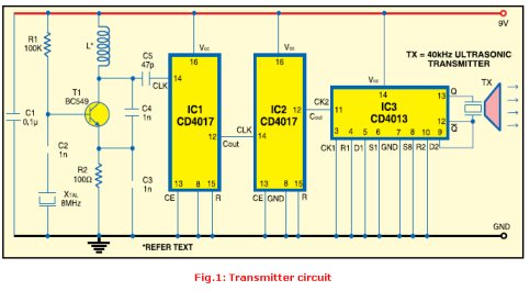
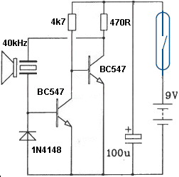
You need to do your homework to find out the absolute minimum number of
components required to perform a particular task.
The transistor oscillator circuit automatically oscillates at 40kHz because the transducer
operates as a CRYSTAL and it's just like a CRYSTAL OSCILLATOR. How simple
and how clever !
All these "tricks" are very important to remember. You will never find them in
any text book. That's why this "Spot The Mistake" section is so important. It
covers things that cannot be covered anywhere else.
![]()
Here is a circuit that is up-side-down:
![]()
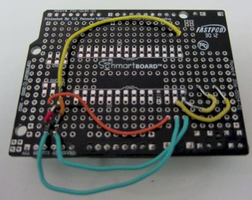
It is easy to connect to each pin from your IC to components on the
SchmartBoard
I have never seen such as disgusting mess in all my life. Doesn't Gary have any
respect for his responsibility as a technical person, to show how to produce a
quality project ????
![]()
That's why we have put the answer here. 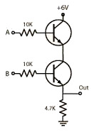
Here is the second reply:
But it is interesting to see 4 different results for a simple requirement. ![]()
The power supply will be a 6V 100mA solar cell.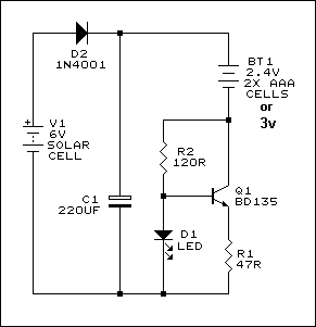
D2 protects the circuit against reverse polarity and also prevents the battery
from discharging into the solar cell when it's dark. C1 is a smoothing
capacitor.
The circuit built around Q1 is a simple constant current sink. When sufficient
voltage is available from the solar cell, R2 biases Q1 ON and current flows into
the rechargeable cells.
If the voltage between Q1 collector and the negative rail starts to approach
around 1.8~2.0V, D1 will start to illuminate. If your solar cell is able to
produce about 4.8V or more, D1 will limit Q1's base voltage to about 1.8~2.0V
(assuming it's a standard red LED) and this will limit the voltage across R1 to
about 1.2V, limiting the charging current to about 25 mA (from I = V / R with
V=1.2 and R=47).
If your batteries are rated at 550 mAh and your solar cell is producing at least
4.8V, the batteries should charge from fully flat to fully charged in about 22
hours (calculated from 550 mAh / 25 mA).
The circuit does not detect when the batteries are fully charged. It will
continue to charge them at 25 mA while there is sufficient voltage from the
solar panel. This is a "trickle charge" and will not damage them since it's only
1/22 of their 1C charge current.
My reply:
If the solar cells are 100mA you need to have a circuit that uses the available
current.
You just need a diode and connect the solar panel directly across the 2x AAA
cells. Take them off after a days sunlight.
Why wait 3 days to charge 2 AAA cells?????
What waste 75mA ??
Why buy a 100mA solar panel and only use 25mA ??
2nd reply:
A spec of 100mA only means the solar cell is able to deliver up to 100mA before
seriously dropping in voltage.
In fact a solar works exactly the opposite.
As the sun shines brighter, the voltage and current from a solar panel (solar
cell) increases and it will magically adapt to any battery it is charging. It is
best to have the battery voltage near to the maximum voltage produced by the
panel but the panel needs to have at least 6v extra available to cater for the
floating voltage produced by a battery and allow the extra voltage produced by
the panel to convert to current.
It is only when the maximum voltage produce by the panel is achieved, will the
maximum current flow.
3rd reply:
A solar cell is a voltage source. It will deliver current to a load as long as
the rated current of the solar cell is not exceeded.
This is WRONG
You cannot exceed the rated current of a solar cell. If the panel is 100mA, it
will never deliver 150mA.
The replies then get mixed up with a LOAD on a solar panel and a battery
connected across the panel.
A battery being charged is not the same as a LOAD. A load conforms to
Ohm's Law and as the current increases through the load, the voltage across it
increases.
A battery is similar to a zener diode.
No current flows until the voltage produced by the panel is greater than the
voltage of the battery and when the sun increases in brightness, the voltage
produced by the the panel would increase. But in this case the battery voltage
does not increase (only very slightly) and the current increases until it is the
maximum the panel will deliver.
Finally, the reply from one of the moderators:
In your case I think your best option is to charge the cells directly from the
solar panel with just a diode in between them.
That is EXACTLY what I said.
The last 2 replies were then magically removed from the forum because the
Moderators realised they had made such a mess of their answers.
In fact you don't even need the diode. If it is very sunny day, the cells will
be charged in 6 hours (if they are fully discharged) and removing them from the
charger will mean you don't need a diode.
![]()
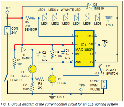
Here is another STUPID circuit from ELECTRONICS FOR YOU September 2014
It is an EMERGENCY LIGHT that is supposed to operate from a 1.5v cell that is
"almost dead."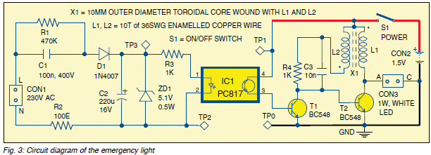
But the worst part is the Joule Thief circuit.
The circuit is supposed to be connected to the battery all the time so it turns
ON when the AC fails. That's the whole point of the circuit.
But when the switch is closed, current flows through the transistor in the
opto-coupler and base-emitter of the first transistor and the battery will be
flat in a few days!!
These two components will allow anything from a few mA to 100mA or more to flow
as we don't know the conduction of the transistor and the base-emitter junction
will drop only 0.7v. There is no current-limiting resistor in this circuit and
this type of arrangement must be avoided totally.
These two transistors are like turning on all the taps in the house so the
garden tap wont drip. There are keeping the circuit turned off by
wasting 100mA !!!
But the worst part of the circuit is the BC547 transistor driving the
oscillator.
This transistor will only pass 100mA and since the circuit is only delivering
spikes to the LED for less than 50% of the time, the average current will be
50mA.
A 1watt LED draws 300mA @ 3.6v. This is 600mA @ 1.5v and the transistor
would have to pass 1.2 AMP to generate full brightness. How are you going to get
anything like 1 amp from a old cell?
This circuit is far from suitable for driving a 1 watt LED and no-one has tested
it to see how useless it is and the fact that it will flatten the battery when
waiting for the AC to fail.
Here is the absurd description of how the transformer works:
When switch S1 is closed and the battery is connected at CON2 (and AC mains
supply is not available),
current flows into the base of transistor T2, the voltage across its base and
emitter rises and the transistor is
switched on. This means that a larger current can now flow through primary
winding L1 of transformer X1
and then through the transistor. This collector current generates a magnetic
field in the toroidal transformer
in a direction opposite to the field created by the base current through its
secondary winding L2.
This is totally false. The current created
in the feedback winding is in ADDITION to that provided by the 1k and turns the
transistor on HARDER. So he has absolutely NO IDEA how the circuit works.
As soon as the primary current becomes greater than the secondary current, the
voltage on the secondary
winding reverses which, in turn, switches off transistor T2.
Absolute RUBBISH.
The magnetic field
collapses and white
LED is switched on. This allows the 1W white LED to be lit from a single
1.5V/1.2V battery, which otherwise
requires a 3.2V DC source or more.
The explanation is totally FALSE. I know the operation of the transformer is
complex, but to dish out this sort of rubbish to 40,000 Indian readers is a disaster.
But, then, none of the staff at Electronics For You have any idea how the
transformer works either.
See our LED Torch Projects for the operation of a Joule Thief circuit.
![]()
RadioShack is running out of cash and will end up in bankruptcy court after a
long, gradual demise.
RadioShack has always been a terrible place to buy anything electronic.
It has never been a good electronics store and was only kept alive with a few of
its good products, like 200-in-one electronics kits, gold detectors and
CB radios.
Their computer products were successful for a time but the market was taken over
by the IBM PC due to the enormous number of programs that were developed for the
clone version of this computer. See TRS-80,
http://en.wikipedia.org/wiki/TRS-80_Color_Computer. The other major failure
of the company was the quality of the components. There were always "sweepings
off the floor."
Putting 5 resistors in a pack for $2.00 is not cheap and selling a 555 for $1.99
is only for an idiot buyer.
At one stage (over 30 years ago), their major sales were components as CB radios
died due to mobile phones, the computer market was dominated by the IBM PC and
the demand for sound systems died due to many factors.
Their books were also very poor but the books from a prolific writer Forrest M
Mimms III must have contributed to 50% of the overall sales.
The company never added to his range and I wrote to their head office over 30
years ago with a book proposal and NEVER GOT A REPLY.
That's how incompetent that are.
Tandy deserve to GO UNDER - DIE - BITE THE DUST - DISAPPEAR.
They have been a blight on the market ever since their inception and every since
their attitude to electronics hobbyists.
They have done nothing to advance the cause and it is no wonder Dick Smith was
able to come in and scoop the market.
Tandy was always a "junk shop" with everything HALF FINISHED. At one stage
you could buy some parts for kits (at enormous prices) but not all the
components.
They had NO professional intelligent electronics person in head office and yet
there were 120,000,000 Americans living in the US at the time.
You would think one person would "stick his head up" and say: let's produce an
electronics magazine ON ELECTRONICS, for electronics experimenters and sell them
in the stores and get 300 enthusiastic customers to each store each month.
They could have introduced a book club, a kit club and an electronics club at NO
COST and yet absolutely NOTHING was done.
That's the intelligence of the American.
The only reason ANYTHING succeeds in the US is due to the enormous
population.
Nearly everything is extremely poor quality but the enormous amount of
"foot-traffic" keeps the shops open.
They don't have to sell quality, just variety.
And Tandy is an example of RUBBISH.
That's why they have finally bitten the dust. ![]()
SCUM
It's only happened a few times where readers have ordered a number of
kits and presented a bogus credit card.
That's why I have stopped taking credit cards and only use PayPal.
But recently kent winchester of
kentwinchester77@gmail.com sent me a request for 500 Metal Detector
projects.
I asked him who he was going to sell them to and he replied:
I have customers. And I want to recommend you to a shipping company that will be
able to ship the packages to my client destination. The shipping company email
address is : LTLfreightshippingcompanies@outlook.com . I want you to email them
and find out the freight cost as soon as you have it email me with the total and
I will submit my credit card for you to run and have the materials shipped out
asap.
I will be expecting a reply from you.
Shipping Address
Street Wabbitwatchin Excursions
City, Pósthólf 1034
Country,ICELAND
Postal/Zip Code,Pósthólf 1034
I immediately Googled
kent winchester SCAM and up came a
huge page of scams.
It works like this:
The customer is asked to send a big consignment to a warehouse using his
shipping company. The shipping company does snot exist. He is the shipping
company.
He pays you with a stolen credit card and you pay the shipping company with your
own credit card within a few hours of getting his card details.
Kent Winchester gets payment for shipping and instantly removes the money from
the shipping account.
You send $6,000 worth of goods to a bogus warehouse and lose $1,000 in shipping
costs.
It's a simple SCAM that has cost a lot of people a lot of money.
http://glassmagazine.com/glassblog/warning-fake-shipping-company-scam?page=3
![]()
I have a variable power supply, used to test motors and run accessories
(motor & tire lathe's) for Slot Cars.
The power supply as it came from the manufacture had a 6.3v 6 amp transformer. I
needed a bit more current, so I installed a 12.6v 8 amp transformer in the case.
The Linear Voltage Regulators that came with the power supply are LM350T's, 3 of
them wired in parallel giving me 9 amp capability.
The power supply is designed to use the case as a heat sink and it runs REALLY
hot,. There is no fan to move air over the case. I want to see if there is
something I could do to cool the case.
The first three replies suggested going back to a 6.3v 8-amp
transformer, adding a fan or using a power supply from a lap top.
Hardly realistic solutions. The other suggestions involved adding a heatsink to
the inside or outside of the case but the person did not want to go to all the
extra work.
I suggested adding a number of 10 amp bridges between the transformer and the
bridge in the case, in an arrangement called "Daisy Chaining."
Daisy chaining multiple bridges together will merely result in only half of
the other bridges actually being used... You should do away with that idea, and
if reducing the voltage to the regulators are the proposed solution, wouldn't
the better options be a new transformer, reducing the coils on the secondary, or
cascading diodes after the bridge?
There are 4 mistakes in the reply. Adding additional bridges drops about 1.4v
per bridge and even though only two diodes in each bridge are used, the whole
idea of the bridge is to remove 1.4 x 8 = up to 11 watts from the regulators.
Eleven watts is an ENORMOUS amount of heat and the bridge is easy to fix to the
case with a screw. Individual 8 amp diodes are called stud diodes and
these need to be screwed to a heatsink and are not insulated or isolated, so
individual diodes are a bad suggestion.
Replacing the transformer is out of the question and removing some of the turns
on an 8 amp transformer is a very difficult thing to do.
The only economical answer is to add some 10 amp bridges and place them away
from the regulators and on very good heatsinks to evenly distribute the heat. ![]()
![]()

I have included it here because some of the projects don't work. Some of
the links don't work and some of the circuits are so small you cannot read the
values.
However it is good source of information and ideas. Some of our circuits are
also on the site.
Here is a website with all the old USA electronics magazines:
http://www.americanradiohistory.com/Popular-Electronics-Guide.htm
http://www.americanradiohistory.com/Radio_News_Master_Page_Guide.htm
http://www.americanradiohistory.com/Electronic_World_Master_Page.htm
http://www.americanradiohistory.com/Radio_Electronics _Master_Page.htm
http://www.americanradiohistory.com/Electronics%20_Illustrated_Master_Page.htm
http://www.americanradiohistory.com/Radio_Craft_Master_Page_Guide.htm
![]()
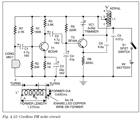
The value of R1 is far too low. Electret microphones are very sensitive and only
need a very small current for the operation.
A load resistor of 100k is needed for 12v supply and if a low-resistance is
used, the microphone starts to produce a lot of background noise.
What is the purpose of R2 and R3 in parallel????
A 47R can be used.
The output transistor has a heatsink. Why??? The maximum
voltage-on the base is 6v as it is being driven by the emitter-follower
transistorT1 and the base of this transistor has a voltage-divider of 10k and
10k on the base.
The maximum voltage across R5 will be less than 6v and this will allow a maximum
of 60mA to flow. The wattage will be a maximum of 35mW and the transistor will
not heat up AT ALL. The loss in R5 will be a maximum of 35mW, so why is a 500mW
resistor specified.
These are the sort of mistakes that show the designer has NO electronics ability
and the technical staff at Electronics For You Magazine have no
understanding of electronics either.
![]()
Although this circuit is very handy, it had one major mistake. The two
transistors were DIRECTLY COUPLED.
This means a very high current will flow though the emitter-base junction of the
BC557 and collector-emitter junction of the BC547 when the two transistors are
turned ON.
This may not be important for a 3v supply, but shows a lack of understanding on
how to design a circuit.
A 1k resistor has been added to prevent this high current flowing and is shown
in red on the diagram above.
I have already pointed this problem out to a design engineer and he agreed, the
current reduction was considerable.
The faulty circuit should NOT be published in Electronics For You
Magazine.
![]()
Here's a typical example of why you should draw a circuit so it is easy to understand:
Look at the thin copper wire. When it breaks the reset pin of the 555 goes HIGH
and the chip turns ON.
But look carefully at the circuit. Does pin 4 rise higher than 0v ????
![]()
Here we have a TOTALLY ILLEGAL circuit from CHIP TALK eBook
You are not permitted to connect the neutral wire to the earth. These must
always be kept separate.
This circuit has the active lead (P) connected to the circuit and eventually
going to the doorbell switch without ANY ISOLATION. A doorbell switch is not
rated for 240v operation and anyone pushing the switch can get a shock if a
fault occurs.
![]()
The top transistor should be drawn as a PNP: from CHIP TALK eBook
![]()
Here is the cover of CHIP TALK eBook.
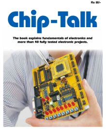
The cover has nothing to do with the simple projects in the book. It is just
another fraudulent con from ELECTRONICS FOR YOU magazine.
Here are some of the mistakes:
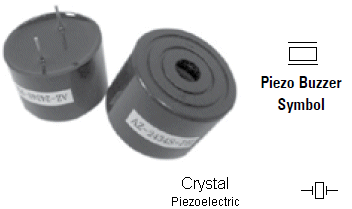
The Piezo Buzzer symbol is the same as a Crystal.
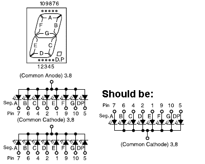
The LEDs should not be shown UP-SIDE-DOWN for a Common Cathode display.
This is a very DANGEROUS power supply.
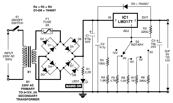
When the switch is changed from 3v to 5v, the output will instantly rise to 12v
during the switching action and blow up the 5v circuit.
8R speaker on a 9v supply will take 1 amp!
If the speaker is being access via a square-wave of 50%, the current will be
500mA. The BC547 can only handle 100mA.
The circuit has 4 red LEDs in series. This produces a characteristic voltage
drop of 4 x 1.7v = 6.8v
The circuit also has 4 x green LEDs in series. Each green LED requires a voltage
of 2.1v = 8.4v.
But the circuit only has 6.8v across A and B. The green LEDs will
not illuminate.
Another circuit that has not been tested.
Why use a relay for a simple job of making Pin 13 HIGH or LOW?
Just another BAD design.
You need a single 470R current-limiting resistor on the cathodes to limit the
current to 10mA.
A single 1k resistor on the common-line of the 7-segment display is a BAD idea.
Each segment line should have a 470R resistor.
The 1k resistor will allow a maximum of 7mA and when the figure "8" is showing,
each segment will have to share the 8mA and get 1mA. The display will be
very dull. Another untried project.
The voltage on pin2 of the 555 has to change between 1/3 rail voltage and 2/3
rail voltage but the base-emitter junction of T2 keeps the pin at about 0.6v.
Another BADLY-designed circuit.
What is the purpose of R4? It can be omitted.
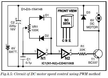
A transistor effectively divides the value of the base resistor by the gain of
the transistor.
If the gain of the BC337 is 100, the 22k resistor turns the transistor into a
22,000/100 = 220R resistor.
This means it will allow 30mA for the motor.
Working it out another way: 22k will deliver 0.3mA into the base of the
transistor. If the transistor has a gain of 200, this will produce a collector
current of 60mA. Another BADLY designed circuit that has not been tested.
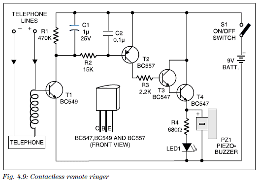
The coil must be around only one of the telephone wires. The circuit would be
much more reliable if the other end of the coil is connected to the emitter as
this would deliver a guaranteed voltage to the base.
The 2k7 R7 should be 22k to 47k. A low value load resistor will make the
microphone too sensitive and produce a lot of "frying" sounds.
4u7 C1 can be 22n to 100n.
47p C4 should be 1n
C6 6u8 should be 6p8
The tank coil between B and C should be 5 turns.
![]()
BATTERY FAULT
Here is a simple circuit that drops the 6v from the two coin cells to 5v1 via the zener diode:
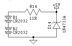
The problem is this:
The zener diode will conduct when the voltage is above 5v1 and current will flow
through the 11R because no switch is included.
The current will initially be 6v - 5.1v = 0.9v/11R = 0.08amps. This is
80mA !!!!
The current will continue to flow until the battery voltage is 5.1v and at this
point the current will be zero. This means an average current of 40mA will flow.
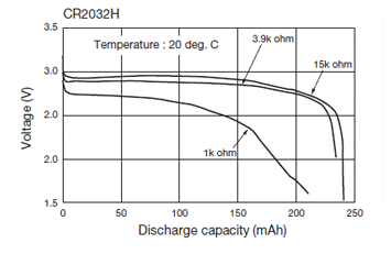
From the graph you can see the voltage of a coin cell remains very nearly 3v
until almost the end of its life.
The 5v1 zener is going to drop the voltage of each cell to 2.55v and about 90%
of the energy will have been removed by the time it reaches 2.55v.
![]()
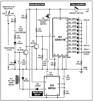
HOUSE ALARM
Here's a perfect example, why a circuit diagram should be easy to read.
This circuit was found on the web:
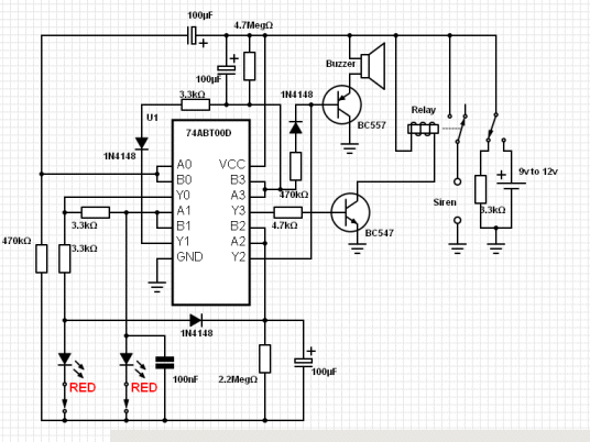
The operation of the circuit was very hard to understand, so the "block diagram" of the IC was converted to gates:
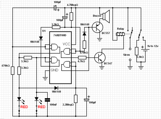
The circuit was then converted to a "linear layout" and it was suddenly realised that the circuit had been copied directly from Talking Electronics website:
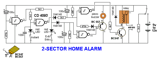
I could not follow the original layout AT ALL.
How can you expect a BEGINNER to understand what is happening with the circuit?
It's no winder readers are confused and not learning anything from many of the
circuits on the web.
The whole idea of a circuit is to simplify the operation of the project - not
make it more complex.
This project can be found in
100 IC CIRCUITS as
Alarm - Home - 2 Sector and the
PC board is available for $3.50
![]()
AUTOMATIC LAMP
I have been telling the CEO of Electronics For You to stop presenting STUPID circuits from Professor
Mohan Kumar. He knows NOTING about electronics and his circuits DO NOT WORK.

Professor Mohan Kumar
Here is another example.
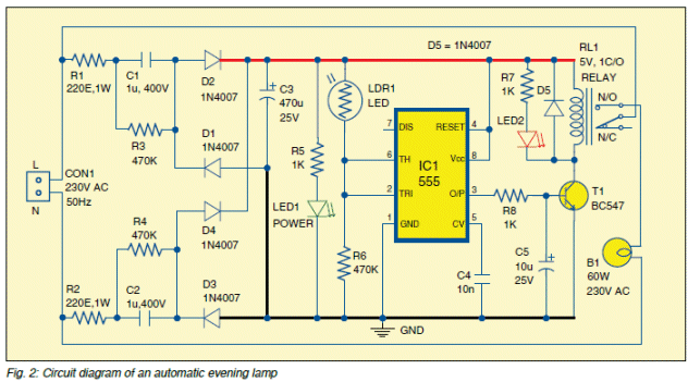
The circuit is a capacitor-fed power supply and we have covered this type of
circuit in full detail in previous discussions.
It is a very difficult circuit to understand and that's why so many designers
make mistakes with it.
Basically it is a CONSTANT CURRENT power supply and with two 1u capacitors in
the front-end, the resulting capacitance is 0.5u as they are in series.
A 0.5u capacitor in a full-wave set-up will deliver 35mA.
Here's the next fact you have to understand.
The output of a capacitor-fed power supply will be 345v if there is NO LOAD.
When you connect a load, the voltage drops. The final voltage will depend on the
resistance of the load.
If the load is 1k, the voltage will be 35v as the current through 1k will be
35mA.
If the load is 500R, the voltage will be 17.5v.
In the circuit above, the load is 1k and a 555. The 555 takes about 10mA,
leaving 25mA for the 1k resistor.
This puts about 25v across the resistor.
This voltage will also appear across the 555. But the maximum voltage for a 555
is 18v.
So? What happens.
I don't know.
Maybe the 555 takes more than 10mA when the voltage reaches 18v and everything
will operate, but the 555 is being over-driven.
We have now used up all the current from the power supply.
So, what happens when the relay is energised?
I don't know.
I don't know the current taken by the relay.
But there is nothing available from the supply.
So, when the relay is energised, the rail voltage drops and less current flows
through the 1k and maybe some comes from the 555. If the relay wants 50mA or
100mA, nothing will work. If the relay needs 25mA, it MAY work.
The whole circuit is just a mess and shows the engineers at EFY don't have a
clue about electronics.
![]()
Here's a circuit from ELECTRONICS FOR YOU December 2014 from a contributor that doesn't know anything about electronics.
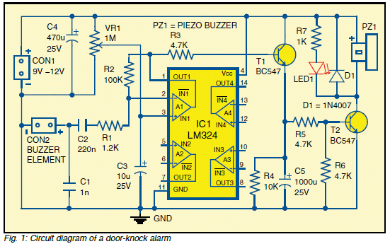
The first mistake is the 220n to the "buzzer element." What is a
"buzzer element?" It should read: piezo diaphragm.
A piezo diaphragm is a ceramic capacitor of about 22n, so the 220n is NOT
NEEDED.
The 1n is not needed and the 1k2 is not needed.
Next we come to the op-amp.
Only 25% of the chip is being used and this could be done with a simple
transistor.
Transistor T1 is an emitter follower and is not needed. The output of the op-amp
is capable of delivering a reasonable current.
Next we come to the 1,000u electrolytic.
The same effect could be obtained with 100u across R6.
All these mistakes show a complete lack of understanding of electronics and to
put them in a magazine, shows the editors do not know anything about
electronics.
I have NEVER seen these types of errors in an Australian, English or USA
publication.
It just makes you cringe at the ineptitude of some of the staff at EFY.
![]()
ELECTRONICS FOR YOU are giving away the magazine for FREE!!!!

A 3-year subscription for 649 INR (about 2-days wage) and you get 8051
Programmer (worth 630 INR).
This is exactly the same competition I faced when trying to introduce Talking
Electronics to the USA.
Poptronics offered a 12 month subscription for $19.95 It cost
Poptronics $6.00 through the subscription houses and with the $12.00 remaining,
it cost 50 cents to post the magazine, 30 cents for the administration and 50
cents for printing. This is $3.60 more than the $12.00 they received!!!!
I then found out they sold 250 magazines per month through the electronics
stores. I was tricked into believing they sold 73,000 copies per month.
12 months later they disappeared, leaving the subscribers with NO ANSWER.
Nuts and Volts offered a free subscription to all those who lost their
subscription.
Nuts and Volts has prospered after this offering. They have never looked
back. They have now combined with Elektor is some form or another,
producing two or more different magazines.
All their magazines are very good productions and worth reading.
ALTERNATIVELY:
You can download the full 2014 year of ELECTRONICS FOR YOU and see all
the mistakes in the
projects I have addressed in the last few pages of SPOT THE MISTAKES:

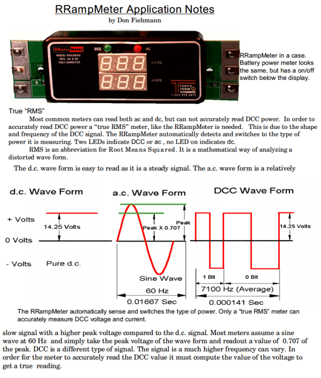
Don Fiehmann has mixed up truth with fiction.
The area under the graph produces the energy of the waveform. For the sinewave, the lower part of the wave is inverted and placed beside the first half-cycle. You can see the small part of the sinewave above the RMS value fills the space between the two half-waves to produce a rectangle equal to the DC waveform.
For an AC waveform you can consider one of the wires does "not move" and the other wire rises to a high voltage and then falls to the low voltage.
When it comes to the DCC waveform, one wire sits at +14.25v and the other wire is 0v. The positive wire then immediately goes to -14.5v.
There is no gradual rise and fall and thus there is no "area under the graph" that needs to be "computed."
ALL the energy from a DCC waveform is passed to the motor (via a bridge) and thus the energy from DCC is equivalent to DC.
This means there is no "computing the value of the voltage." It is simply the voltage on the two wires (multiplied by time) and 100% is delivered to the motor (minus the losses in the bridge). That's why trying to introduce the term RMS does NOT apply and this piece of electronic mumbo jumbo by Don Fiehmann needs to be corrected.
Reply from:
Larry Maier
Tech Support
Tony's Train Exchange
The peak to peak voltage is 28.5 volts, but the RMS value of the shown DCC waveform is 14.25
When the shown DCC waveform is rectified with a full wave rectifier, it produces (approximately) 12.8 volts DC, which is suitable for operating the 12VDC motor found in most engines.
If you perform an RMS operation on a DC voltage, the result is simply the DC voltage. This is a pointless exercise.
Introducing RMS tries to make the project more complex than it is. It simply measures the peak voltage and does not consider it to be an AC waveform. Otherwise it will produce a figure of 0.707 x the reading.
The term RMS was "invented" or started to be introduced when alternating current was first delivered to homes at the beginning of the invention of electricity (electricity to the home).
The original electricity was DC (called DIRECT CURRENT - but actually means DIRECT VOLTAGE) and the voltage (and current) was present at all times when the "electricity" flowed.
When you turned on a 1,000 watt radiator you received 1,000 watts of HEAT. The voltage was 110 volts.
But when AC (alternating current) was introduced, (actually ALTERNATING VOLTAGE) the voltage has to rise higher than 110v because the voltage dropped below 110v for part of the cycle and to "make up" for the drop, the "rise" had to be higher. This means the "peak" had to be about 41% higher to make ALTERNATING VOLTAGE equal to DIRECT VOLTAGE.
Everyone was scared about "electricity" at that time and rather than say the new voltage was "162 volts" they just kept the old voltage of 110v to 120v on all the "stickers" (name plates) and "secretly" increased the peak to 162v.
RMS mean EQUIVALENT TO DC.
For DCC the peak voltage is the same as RMS and no calculation or conversion needs to be made.
![]()
WHEEL OF FORTUNE
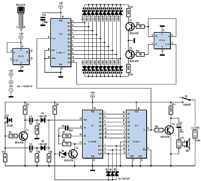
This circuit can be replaced by a single 8-pin
microcontroller.
Here is the scan circuit to activate the 20 LEDs. Pin 4 accepts a switch and the
output lines are gated to drive a "clicking circuit" to represent the wheel
turning.
![]()
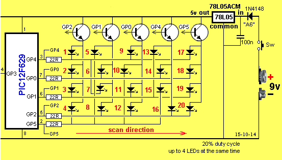
More mistakes from Electronics For You Magazine January 2015
How are you going to illuminate a 1 watt LED through a 220 ohm resistor????
It should be about 220 milliohm = 0.22ohm = 0.22R = R22 The resistor is one thousand times too large !!!!!!
I saw this fault INSTANTLY. None of the staff at EFY picked up the mistake. It was repeated 6 times in the project !!! How dumb can you be ????
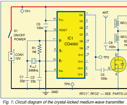
A CD4060 will not work at 24MHz. It goes to about 12MHz max.
The only problem with this circuit is the current delivered to the LEDs. The 1u capacitor will deliver about 70mA in full-wave and this delivers 35mA to each string of LEDs. A 5mm LED needs 17mA and 25mA max. 35mA will limit its life considerably.
![]()
Now we come to projects in Everyday Practical Electronics.
They reply from Matt Pulzer: We have so many projects awaiting publication at the moment that I am not accepting further submissions for now.
The project he is referring to come from Silicon Chip and are re-presented in the magazine 12 months AFTER they are released in Australia.
These kits were backed up by Jaycar but the response was so poor that Jaycar has pulled their entire advertising over 12 months ago.
I then contacted all the advertisers in EPE to see if they were interested in supplying kits. The response surprised me. None were even the slightest bit interested and one said the projects were "boring old amplifier that no-one wanted to build. He had already contacts the editor with suggestions and the email "fell on deaf ears."
I have to say I have never read EPE but the past issues had lots of beginner projects. As soon as Silicon Chip took over, these projects disappeared.
I contacted Silicon Chip with a small project and the reply from Leo Simpson was::
I am afraid your intruder alarm would not get to first base. Put simply, the PCB is not big enough to accommodate all the components - the battery holder is only half on the PCB. Nor are there any mounting holes for the PCB. There is not enough supply bypassing with only 10uF & 100nF capacitors and there does not appear to be any input protection for the micro.
I thought Leo Simpson had some understanding of electronics. But to say the PCB is not large enough is absolutely absurd. The battery holder is a 3v coin cell holder and it has two very strong pins. It does not have to be fully mounted on the PC board. He could have said: "could we make the PCB longer" . . . . . .
If you look at their PCB's and the cost of many at $10.00 it is no-wonder they sell 1 to 5 boards over a period of 18 months. Their projects are simply not popular because the board is too expensive and no-one provides a back-up kit.
You don't need mounting holes for a small board that is going to be placed on a shelf with the PIR detector.
Then he really caps it off with his understanding of electronics when he says:
There is not enough supply bypassing with only 10uF & 100nF capacitors and there does not appear to be any input protection for the micro.
The Intruder Alarm project takes 1.5mA 10u electrolytic is ample for 1.5mA and 100n is across the chip.
Then when he says there is no input protection - - - - - I ask him: " where do you put the input protection?????
He complains about my small PC boards but have a look at this board for $15.00 Australian or about $30.00 UK.
Not only is the board twice the size it should be but it has no legend.
Here's another example of a board without any component markings. Imagine how
difficult it will be to place the components correctly when you have a bare
board filled with holes.
I was one of the first magazines in the world to provide PC boards on the front
of the magazine with component identification.
I still have a box of boards from EPE's previous magazine, Everyday Electronics,
without overlays and it is almost impossible to build them. They don't even have
a name on the board !!!
Here's another poor quality presentation. The board has obviously been hand
etched and doesn't have a solder mask or tinned lands.
I would not put this piece of rubbish in a magazine as an example of how to
build an electronic project. A board like this would cost less than $3.00 to get
professionally made and avoid the embarrassment of someone criticizing it.
Now we come to a technical mistake in LED Lady Bird.
I have provided my comments in blue. The project uses a PIC micro, a 3v
lithium cell and a number of LEDs without any current-limiting resistors.
LEDs1-22 are driven directly by IC1’s output ports, without current-limiting
resistors. This was done both to save on the parts count and because there’s no
space for current-limiting resistors on the PCB.
BELLBIRD
Driving the LEDs in this way is quite acceptable provided we don’t cause too
much current to flow in the output pins.
In this circuit, the maximum supply voltage is around 3.3V (with fresh cells)
and this prevents each output from sinking more than about 21mA.
This is NOT TRUE.
This is within the limits allowed for both the microcontroller’s output pins and
for the LEDs.
How do we arrive at that figure? Well, the impedance of the output pins is
typically 70 ohms and there will be 1.8V across each LED when it is on. This
means that, with a 3.3V supply, the voltage across the 70ohm output impedance
will be 1.5V, so the current through the LEDs will be 1.5V ÷ 70 = 21mA.
This is NOT the way to work out the maximum WATTAGE
allowable for each output.
The maximum allowable current for each output is 21 to 25mA but this is assuming
the output FET is FULLY TURNED ON. When it is fully turned on, the voltage
across the FET is only about 50mV to 100mV.
This gives a wattage or milliwatt rating for each output.
But when a LED is connected directly between an output pin and the supply rail,
the LED produces a characteristic voltage across it of 1.7v for a red LED and
the remaining voltage appears across the FET on the output of the micro.
In this project there is a fully turned ON transistor in the drive-line and the
battery voltage can fluctuate from 3.3v down to 2.5v.
However if say 3.3v - 0.2v across the transistor - 1.7v across the LED = 1.4v
across the FET. This is considerably more than the normal 100mV and the FET will
try to dissipate up to 10 times more than its specification.
This is just a point that the author
John Clarke is not aware of.
There are a number of technical mistakes in the circuit. Here they are:
The 74C14 IC is used to provide reversal on the output to deliver 5v to 6v to
the piezo.
But when the chip is supplied with 3v, the outputs of this IC will deliver very
little current. The output of a micro is about 20mA to 25mA over the full range
of supply voltage, but the 74C14 has problems at 3v. This means the output
voltage will not be rail-to-rail. The chip could be wired to deliver 3 outputs
plus 3 outputs, rather than wasting 2 gates.
The 1k in series with the piezo diaphragm reduces the output because the piezo
is effectively equal to about 20n and this makes it about 2,500 ohms at 2800Hz
and when combined with 56n, the voltage is divided (reduced) to less than 40%.
The piezo can be connected directly to the output of the micro and the volume
will be the same or louder than the circuit above. Switching (reversing) the
voltage makes very little difference to the output volume with such small
voltages.
It is difficult to see the reason why the LEDs are connected to all the
different value resistors when any effects can be produced by pulsed operation
from the micro.
1u monoblocks are not needed. 100n is sufficient.
Just an overdesigned circuit. I don't like the arrows on the leads of the piezo,
it infers the piezo is providing a waveform to the circuit, whereas it is
receiving a waveform. The LEDs in parallel will get very little current from a
3v supply. The text says the circuit takes 1.5mA when operating. 0.75mA is
not very much for a LED. 470k on the LDR means the LDR must go to about 1M
to reduce the voltage on the pin to create a LOW. Most of the small LDR's
go to about 750k and pin 6 may not see a LOW. The resistor should be about
220k for reliable turn-off.
This whole circuit could be done with an 8-pin chip, rather than wasting an 18
pin chip.
Here is a "cry in the wilderness:"

Go to the chat room. Apart from the difficulty in getting a password to enter,
the Forum sees less than 10 visitors a day. How can you get a response when
almost no-one is visiting the Forum???
Why doesn't EPE provide a list of suppliers who will provide a kit for the
project. Why? Because NO-ONE is interested in providing kits
that DO NOT SELL.
Jaycar pulled their advertising over 12 months ago because the response was
ZERO.
The Projects are simply NOT popular. This is proof as the sales from
Silicon Chip site show 1 to 5 PC boards in a period of 18 months. EPE are
getting the boards made on a '"one-off" basis, when you order. What a
"hand-to-mouth" existence.
Sales have plummeted from a circulation of 73,000 (this means a readership of 73,000 and sold copies of 43,00 - another impressive STUNT from most magazines) to 35,000 "sales" (whatever sales means) to 10,000 (and less) actual sold copies in just 20 years. The reason is the internet has taken over with hobbyists going to You Tube, Make and Instructables.
A magazine is not viable under 15,000 when you think of the cost that goes into its production and printing and the dwindling return from advertising.
EPE has only remained afloat by re-releasing old material that does not cost them anything, compared with generating new designs. And you can see by their Alexia website global traffic rating of 3,044,165 it is not in the run for any award. Talking Electronics is 179,864 and it gets 6,000 visitors each day. This is a 16:1 ratio and EPE has had a visual representation in the market for over 25 years. This is an appalling indictment of how NOT to presents electronics to the hobbyist and enthusiast.
Alan Winstanley of EPE has some "Mickey Mouse" Soldering Guide that he wants beginners to pay $9.00 to $18.00 for a Kindle version or paper-format.

Thus is a terrible guide. Look on Amazon for a preview to see how much
unnecessary information (verbiage) is presented. It
is out of date, (he talks about a temperature-controlled iron for $80.00 whereas
they are now $10.00) out of touch with reality (does not talk about copper-wire
sponge and lots of other things) and I have produced a
FREE guide to soldering
containing all the points missed out by all these "guides." They are
just mountains of verbiage.
You have to provide something worthwhile on a website to get visitors coming
back again and again and the internet is the way of the future. The two
magazines have nothing. They just want to squeeze "the last drop of blood" out
of a dwindling audience and try to charge for every minute item.
Even on the internet, the conversion-rate can be as high as 50,000:1. In other
words it needs 50,000 views of a project to get one order or one person
constructing. With sales of 10,000 for a publication, you can hardly get one
sale for each page of advertising.
Things have changed over the past 20 years. Conversion rates were 1% to 5%. Not
now. The reader has such a wide variety of options and choices. And of course
computer games, Facebook and Apps?? have taken over.
You Tube projects, Make projects or Instructables are getting
50,000 views.
Compare that to 10,000 sales of a magazine. Magazines are DEAD.
Anyone who does not see the "writing on the wall" for the print media is burring their head in the
sand and simply "re-arranging the deck-chairs on the Titanic." The
only publication to increase its sales this year is Charlie Hebdo. All the rest
are on their "last legs."
It's a sad situation but magazines are not providing any instructional
videos to back-up their project. They don't offer any kits and have stupid
prices for PC boards. They do nothing in their favour.
The Chinese produce boards at 10% the price of all other manufacturers.
Magazines have NEVER offered this and NEVER passed on the lower prices. The
same with kits.
The Chinese offer kits with free postage for 10% of the cost of magazine kits.
Readers are starting to become aware of this and eBay has taken over as the
largest sales of electronics components. Electronics suppliers are nearly
doomed too. It just takes time to see them go. You can buy ANYTHING on eBay.
You can fool some of the people some of the time but not all the people all the
time.
I didn't want to start a magazine in the first place.
I knew it was impossible to design projects, write them up in "publisher format", draw the circuits, take photos, layout the pages, pay for printing and handle the advertisers.
So about 1980 I sent a letter to Electronics Australia with a suggestion to the Technical Editor Jim Rowe that I would supply some beginners projects. At the time they had one or projects in each issue and I thought to add to this with a larger range of projects.
He accepted my offer. On the second page of his typewritten reply, he said, Oh, by the way, if you fail to deliver the projects by about 23rd of the month, there is a penalty of $2,400.
That is equal to $20,000 today. I bought my first block of land for $2,000 - so the "fine" was ENORMOUS.
That spurred me to produce the magazine myself. For $2,400 I could get 10,000 copies printed at our local web printer.
From the first day the magazine hit the newsagents I got 80 orders. And I never looked back. The first issue was 32 pages and typed on an electric "Golf Ball" typewriter.
After about a year of running Jim Rowe had the audacity to come to my office with Virginia Salmon (the advertising manager) and say "I suppose you didn't like the penalty in the letter I wrote to you."
What could I say? with 8 staff around me and a woman. I said nothing.
But that's how the opposition tried to stifle me.
But it didn't end there.
After 2 months of operation Electronics Today International sent all their advertising representatives to the advertisers offering 12 months advertising for half price.
I could not get one single advertiser (components supplies) and decided to continue with the magazine WITH NO ADVERTISING.
But that wasn't enough.
The opposition magazine then decided to put out a competition magazine for 95 cents, whereas mine was $1.25.
They continued for 6 months, putting out up to 40,000 copies each month.
Then, one day Colin Rivers rang me to say: "You have won the day."
I didn't know what he meant, so he explained that they were pulling "Hobby Electronics" because I had not folded. It had cost them $50,000.
In the meantime I had learnt from an advertiser that the other magazine was scrutinizing my publication for a single paragraph that could constitute "copywrite infringement" . . . for an all-out court case.
Luckily I never read any of their magazines and nothing of mine even resembled any of their articles.
Now we come to Silicon Chip.
I offered to supply articles to them just recently, but obviously the success of my magazine was still in the mouth of Leo Simpson who realised my approach to writing (and content) outshone their endeavours and he gave some poultry excuse for not wanting to include them.
Obviously EPE could not include them because they had sacked all their production team. They are the losers. With a circulation of 10,000 the number of beginners will be miniscule as not one single beginners project has been presented in either magazine for the past "x" number of years. It would take a long time to get any sort of following because no-one is visiting the newsagents and the content will go unseen. I realise it is too late for them. The time has gone. The trend has changed and the youth of today don't see the need to learn electronics because there is simply no future. All the designing and manufacture is done overseas and the electronics careers have all dried up.
Instead of teaching electronics, Universities should teach "Meet and Greet" because that is the only "job" at the K-Mart or Wall Mart store.
The bottom-line is this:
Neither magazine is interested in producing or assisting the beginner with components.
It is a lot of work to provide kits but that is what I specialised in and made a huge success, selling over 300,000 kits with the FM bug kits selling more than 30,000 of one type alone. The magazines could outsource the requirement and charge a commission on sales.
But the plain, cold, hard fact is: they are not interested.
They put on all the pretense of being successful when the statistics from their websites show a different story.
You can't beat statistics. The first IBM computer in the USA (card version) predicted a win by a small margin to a certain political party and IT WAS RIGHT. From that day, political parties have poured over computer figures. If you don't believe statistics, you are fooling yourself. Look at Ocean's 11 and study its background.
I have outlived 4 magazines and there are only two more to go.
Such is life.
![]()
Here is a kit promoted by Michael Tooley in the January issue of Everyday
Practical Electronics:
Apart from the price of Ł18 (about $35.00) the kit has a number of major flaws:s:
Here is display of the components:
Here is a project:
The major fault with the kit is the BREADBOARD. It is the worst design you can
get. It does not have any power rails. It teaches the completely wrong way to
lay-out a circuit. Look at the way the leads of the battery are poked into the
holes in the breadboard.
This is the sort of photograph I get from readers who don't have a CLUE about
electronics and poke wires into the board "all over the place." Where has "Bob"
from Spiratronics - the producer of the kit and Michael Tooley, the kit
reviewer, been for the past 20 years??? In a cave??? Junk breadboards like this
went out 30 years ago.
I would not even purchase one, let alone show a project using one in a
PROMOTIONAL ADVERTISEMENT.
And the jumpers. You can get proper jumpers on eBay for one cent each !!!!
Secondly, the kit seems to have just 5 projects. At least with a Tandy kit 30in1
or 100in1 you get a lot of projects to try.
Thirdly the kit does not have a piezo diaphragm, a switch or a pot with a shaft.
A piezo diaphragm is very handy for siren
circuits and can even be shown to be a microphone.
Why they would provide a sheet of sandpaper to clean the contacts, is beyond me.
I have never used sandpaper in 40 years!!!
It's just a "Mickey Mouse" kit. In fact it is an embarrassment to all
electronics engineers. And that is as mild as I can get.
The five main projects that can be built with the kit are:
a light-operated switch (which can be extended in order to drive a small relay);
a simple audio amplifier;
a time delay (which can also be extended using a small relay);
a trigger/reset device; and
a heads and tails game.
Michael Tooley says:
The projects are well thought out and cover a variety of different circuits ranging from amplifiers to comparators and light sensors to timers. The circuits are based on a subset of common low-cost semiconductor devices, including LEDs, diodes, NPN and PNP transistors, a 741 operational amplifier and a 555 timer.r.
He says the kit contains 50 components. He has counted ALL THE WIRES too !!! I have never heard of a piece of wire as being a "component."
It looks like it has ONE capacitor in each range, so you can't even make a flip-flop. What a FLOP !!!!
It's just an overpriced kit where you could buy all the parts separately for $10.00 from an electronics store and get dozens of circuits from the internet. You can also get component identification from the internet. So, why pay $35.00 ???? You can get a proper breadboard for $2.00 on eBay plus 50 jumpers for $2.00 post free.
But that's not the whole story. .
It's fortunate very few beginners will be sucked into buying the kit because Everyday Practical Electronics has such a small readership, that almost no-one will be seeing the advertisement.
With a circulation of 10,000 the whole magazine is below viability, however if they are getting the majority of the project-pages "almost free," the small amount they have to spend on "news" items will fill the magazine and they can survive.
It's just the advertisers that are "hood-winked." The advertising blurb still has the old circulation of 20,000 and they have admitted this has dropped to 10,000 in the past 4 years.
At 10,000 it is not worth placing an advertisement.
I have already said the conversion ratio is about 1% and out of those who start to order a kit, only 20% actually place an order.
But this 1% refers to the group of reader INTERESTED in a particular product. The magazines have not presented a beginners project in more than 12 months, so the percentage of beginners reading the magazine will be miniscule.
Most beginners will pick up the magazine at the newsagents and look for articles of interest. Going by my past experience of 30 years in the magazine publishing business, the percentage of beginners is about 20% when suitable projects are presented.
For my magazine it was 100% because that is all I presented.
But for EPE the target audience (to use their terminology) is 2,000. And 1% of 2,000 is 20 orders. At a cost of Ł500 for the advertisement, each order costs Ł25 for an Ł18 kit !!! Simple mathematics !!
Some of the shopping carts ask for details TWICE and some will not process an overseas telephone number.
Shopping carts are an absolute disaster as some don't know what postage to charge, some charge exorbitant postage (like $30 for a $5.00 PCB) and some don't process .com.au addresses. They simply freeze.
For the kit above, the shopping cart charges Ł3.00 for an overseas order. Obviously they have NEVER posted a kit overseas !! They will get a shock at the real cost. That's why shopping carts are a DISASTER.
![]()
The SOLAR ENERGY
scam
I get bombarded with emails every day
about getting SOLAR PANELS on my roof.
It all sounds like a good idea but when you go into the economics and
environmental aspects, you find a different story.
Let's go back to where it all started and do some mathematics.
This whole thing would not have got off the ground if it were not for government
subsidies.
The scheme itself is not sustainable and some clever person persuaded the
government to back the idea on the grounds of ENVIRONMENTALLY FRIENDLY - GREEN
FRIENDLY - "carbon" friendly NONSENSE.
Let's take the economics first.
The original systems were 1,500 watt for about $3,000.
One kilowatt of electricity costs 20 cents. (actually one kilowatt-hour). This
means the solar system generates 30 cents per hour of energy. If the system works for 8
hours a day, it will take 1,250 days to pay-off.
This is 3.5 years. That's not counting cloudy days, interest costs on $3,500 and
inefficiencies.
Many of the original purchasers only paid $500 TOTAL COST. The government paid
the rest.
But here's the problem: A normal household does not use 1.5kW during the
day. The only consumption is a fridge, a light and a TV. This is
800watts. The rest of the energy is pumped into the grid and the owner of
the solar system gets a rebate.
Initially this rebate was 60 cents per unit (per kW-Hr) and that's what made the
whole idea so attractive.
But who do you think is paying the 60 cents per kW-Hr? The other
consumers. Instead of paying 17 cents per unit, they were paying 20 cents per
unit to make up the costing.
Fortunately this SCAM has been uncovered and the rebate has fallen to 30cents
and sometimes 10 cents.
At 10 cents, the whole SOLAR SCAM is not viable. And neither it should be.
It's exactly like me getting an electric car and because I am not polluting the
city with exhaust fumes, I get registration for $100 instead of $500.
The government then increases all other registrations to $550 to make up the
short-fall.
But let's look at the other figures.
It takes 2 years to re-cover the energy expended into making the panels and how
many thousands of gallons of poisoned water is produced to wash the silicon
wafers?
The whole concept is so crazy that I never thought it would get off the ground,
but then I did not think of the FRAUD of getting 60 cents rebate on something
that cost the electricity utilities less than 8 cents to produce. I never thought
they would bow to government pressure like this. It is
EXTORTION and imagine if you were producing say plastic bottles for $1.00 and
the government said you had to accept used plastic bottles from customers for
$3.00 !!! There is NO DIFFERENCE. FRAUD is FRAUD.
It's just no-one has explained it so clearly.
Now the electricity companies have an oversupply of electricity to the extent of
20%, of which 10% is due to solar panels and 10% is due to everyone cutting down
on consumption with LED fixtures and turning off the lights.
This has caused them to increase electricity rates 20%. It's a
spiral.
With peak rates climbing to 60 cents per unit due to smart meters, the time will
come when households will opt for self-generation with battery-back-up.
A normal household uses 24kw-hr per day and this equates to 1kw-hr, but you have
to take into account peak usage.
The biggest user is the tumble dryer. All other high-current devices can be
converted to gas.
You can get 5kW inverters and if you are generating 1.5kW, and the dryer takes
2.4kW, you need to supply 1kW from back-up batteries. A cheap "car battery"
(12v 40A-Hr) will deliver 0.5kW-hr so you need 3 batteries at $70 each as
a minimum back-up.
This will all require a separate inverter unless you have enough batteries to
match the voltage of your solar panels.
All this becomes viable when you consider you are paying $200 per year just for
the connection of the electricity.
A new connection costs between $300 and $1,000 where they make you pay $350 for
the smart meter.
I can remember paying water rates for a property that had no house. Why ???
Because the water "passes the door !!!"
That's what they will do with those who decide to go "off the grid."
No matter which way you look at it, electricity costing is a SCAM.
They sell electricity in bulk to ALCOA (aluminium producers) for 5 cents per kW-Hr.
And the government sells Liquid Petroleum Gas (LPG) to China for 5 cents to 10
cents per litre. It costs us 40 cents per litre.
![]()
Here's an incorrect diagram from an Indian publication:
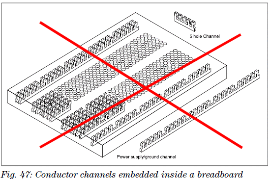
The centre "holes" are connected in sets of 5 as shown:
Can you see his mistake??????
![]()
When you see all these critiques and criticisms, I am not biased. I have an open
mind. If something is well-designed, it gets my tick of acceptance.
Some people are clever and some are not.
One of the cleverest persons in the world was HITLER. Look what he achieved.
The Autobahn, the People's car, the submarine, synthetic fuel and improvements
to the plane, tank, V1, V2 Rocket. Just through his backing, the
design-engineers got to work on so many amazing projects - including the stealth
fighter.
When you think of it, the war was also the basis of the Jet, the Computer and
the rocket.
One of the most absurd "dreams" was the Jet engine. It was "pooh-pooed" by the
British admiralty as preposterous! How can you "blow" an aeroplane along
??? But Frank Whittle was not wrong.
There are (and were) hundreds of clever people who have advanced the world to the
conditions we
are now enjoying. And I have studied the persistence they displayed in
the process to achieving their goal. Look at the "bouncing bomb" and "Tall boy" or
the hovercraft.
Why did I bring up this diverse group of people? Because I feel I fit right
between.
I have been accepted by some and made a great improvement to many peoples lives.
I was accepted as a teacher and taught hundreds of students.
I was accepted as a technician and repaired over 35,000 TV's, radios and
stereos.
When I ran the magazine, I never refused anyone who wanted to work for the
magazine.
I gave them the chance in life that I was given on so many occasions.
In fact one of the lowliest workers produced the greatest income for the
business.
One day he said: One of the customers has brought in a plastic credit card to pay
for the items.
This was the first we had heard of the concept.
I did not want to reject the idea but I was hesitant of its success.
Rather than be "smart," I said I would go to the bank and find out the details.
It cost $70 to get an "impression machine" to handle the cards - which was a lot
of money.
In the next 15 years, credit card sales rose to 50% of overall sales.
The next thing he comes in and says a customer wants a binder for the
magazines.
Again, I took the idea on-board and ordered 100 binders. In the end we
sold over 1,000 binders.
Next he comes in and says a customer wants an FM bug kit made-up.
I thought to myself, what hobbyist would want to but a ready-made item??
But this was a person who wanted to use the bug to listen-in.
I asked if this request had been made before and he said yes.
So I got him to make up 10 bugs.
In the end, half of income was built-up products.
So, you never know who has the brilliant idea and rejecting a person can starve
the world of great ideas.
That's exactly how I feel when the editors of the two magazines above refuse to
include my projects.
It doesn't hurt them, but it is obvious they are refusing all those budding
electronics contributors from both Australia and England.
I have not seen one budding contributor in either magazine.
That's why I say, they should not be in charge of a magazine.
This not only applies to electronics magazines but to all governments, postal
systems, utilities, schools, Universities and the list goes on.
To give someone a TER score of 99.95% to enter University is an absolute
absurdity. No-one gets anything 100% in any endeavour.
It just gives the student the wrong concept in life.
No-one is perfect and the attitudes I have had from University students would
make you cringe.
One student wanted to write for the magazine and when I said I would give him a
kit of parts to help design the project, he said: Oh, I don't do soldering."
Another worked on a project for 4 days and hand-taped the PC board. When it came
back from the PCB manufacturers, all the circuit was back-to-front. He tried to fix
it by bending the legs of the chips around the other way. All the 7-segment
displays showed the wrong segments.
The next day he did not show up. I rang him a 9:30. He said: "you
can stick your job up your arse."
Comments from the two publishers fall next to what I have encountered
from the university students.
That's why professors have slip-on shoes. They have never learnt to tie shoe
laces!!
One student: Oh, Professor you have one brown shoe and one black shoe."
"That's funny, I have another pair just like this in the cupboard."
That's why "intelligent" people should not be in charge of things.
They can't even do up their shoe-laces !!!!
![]()
Here are some corrections and mistakes on Mike Tooley's website:
http://www.miketooley.info/ for
Everyday Electronics Teach-In
In the circuit shown below, the program memory can be cleared by:
This is a very BAD question because the "program" cannot be "cleared" without
erasing the chip.
What does he mean by "cleared"
What does he mean by: "Program Memory"
Does he mean the files used by the program to store temporary data? These
will turn into JUNK when the power is removed.
Does he mean the AREA where the program is located? The program is
"flashed" or "burnt" into the chip and can be erased when another program is to
be "flashed." Some chips can only be programmed ONCE.
The maximum value of current that can be sourced from a single I/O port line of a PIC is:
2
mA
20
mA The maximum is actually 25mA
200
mA
2
A.
The typical supply voltage for a PIC is in the range:
0
V to 6 V
2
V to 6 V The maximum is actually 3v to 5.5v
5
V to 9 V
9
V to 12 V.
The principal elements of a microprocessor system are:
The elements are not your PAL !!!!!!
For a bipolar junction transistor, the collector current is:
only
dependent on the base current
only
dependent on the emitter current
the
sum of the base and emitter currents
the
difference between the emitter and base currents.
I disagree. For a common-emitter stage, the collector current is the
SUM of the base and emitter currents.
An application for a zener diode is:
a
rectifier
a
current limiter
a
power indicator
a
voltage regulator.
A zener diode CAN be used as a rectifier. In fact ALL diodes are zener diodes but the zener (or breakdown) voltage of most diodes is higher than the voltage being rectified and that's why the zener or breakdown voltage is not impotent. You can see a circuit where I used a zener diode to produce a fixed output voltage
A typical operating current for an LED indicator is:
10
to 25 mA High bright LEDs are quite visible at 1mA !!!
25
to 100 mA
100
to 200 mA
more
than 200 mA
The typical forward voltage drop for a diode is:
0.2
V for a germanium diode and 0.6 V for a silicon diode NO
The industry recognised voltage drop for a germanium diode is 0.3.
The industry recognised voltage drop for a Schottky diode is 0.2v
The connections marked 'X' and 'Y' below are:
X
= emitter, Y = collector
X
= collector, Y = emitter
X
= anode, Y = cathode
Y
= cathode, X = anode.
The last two answers are THE SAME !!!!
A typical power rating for a soldering iron for electronic work would be:
18
W
50
W
100
W
150
W.
Both 18watt and 50 watt are correct as a temperature controlled soldering iron
is only turned on for a very short period of time.
In his sample chapter:
chapter (4.6 Mb PDF)
He shows an N-Channel FET being tested with a NEGATIVE voltage on the
gate:
The gate voltage needs to be positive to turn the FET ON.
![]()
Page 1
Page 2
Page 3
Page 4
Page 5
Page 6
Page 7
Page 8
Page 9
Page 10
Page 11
Page 12
Page 13
Page 14
Page 15
Page 16
Page 17
Page 18
Page 19
Page 20
Page 21
Page 23
Page 24