SPOT
Page 1
Page 2
Page 3
Page 4
Page 5
Page 6
Page 7
Page 8
Page 9
These pages allow me to describe all sorts of things that don't fit into
normal articles on circuit designing.
There are actually two different requirements for a text-book.
Some of the most important concepts for understanding electronics is contained
in these pages.
Here's one of the stupidest projects imaginable.
Firstly, most digital meters do not have any adjustment and it is pointless
building an accurate voltage reference.
STREET LIGHT
What are the 9v AC connections ????? How is the AC connected
???
STREET LIGHT
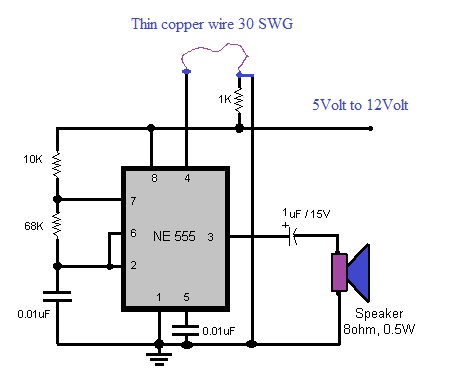
The 555 IC takes 10mA ALL THE TIME and the battery
will be flat in a few weeks !!! The 1k is constantly across the supply.
The 555 will not "turn-ON" when pin 4 is floating.
Here is the poor description of the circuit as presented in Hobby-electron:
The voltage available for the piezo buzzer is less than 9v.
http://hobbyelectron.blogspot.com.au/2011/08/mini-auto-charger-fan-circuit.html
The BC547 is supposed to control the charging of the battery.
When the TSOP1738 turns ON, the transistor inside the detector and the BC558
will allow a very high current to flow because there is no current-limiting
resistor.
You don't need the digit resistors as well as the resistors for the segments. In
fact the digit resistors will make the segments very dull when all the segments
are illuminated. Another circuit that has not been tested.
Let's look at this circuit.
Always check each component to see if it is necessary and look on the web to see
if the same function has been done is a simpler way.
WIND CIRCUIT
Let's look at this WIND CIRCUIT.
Neutral must NEVER be connected to ground.
Another badly designed circuit from T.K. Hareendran
Here is a capacitor-fed supply, dressed-up to look impressive, by using a few "uz"
values, on an Electrical Design Network website, from Raju Baddi:
FLASHER
What is the purpose of the transistor ??
Here's a project for beginners from Jameco Electronics:
It is filled with mistakes. I could not build it and I've had 50 year experience
in electronics.
AUDIO LEDs
The second diagram allows the battery voltage to drop to 5v before the circuit
fails to work.
We have had to reduce the sensitivity of the second stage so the LEDs do not
turn on due to the background noise.
See our 30 LED
Projects eBook for more circuits like this.
FAULTY BRIDGE
I have mentioned on many occasions, DON'T DRAW CIRCUITS IN A
NON-CONVENTIONAL WAY.
Now we go to the second half of the "charging cycle."
Everything looks good until you analyse the circuit and re-draw
it so you can see what is happening:
The Neutral is now producing a POSITIVE waveform and this passes
through diode D1 to the 100u and via ZD2 to the 2u2 and 100R current limiting
resistor.
But he still hasn't learnt how to draw a circuit correctly, so
you can what is happening. It's no wonder he doesn't understand electronics.
You can see the positives of the diodes are at the top and you
can quickly trace through the circuit to see the two charging paths.
Here's another circuit from
Electronics For You
June 2015, that does not work:
The voltage on the top of the LM385 is determined by the 270R
resistor and the four 470R pots in parallel.
The biasing of the transistor will always produce more than 0.7v
and it will be TURNED ON. This circuit by D. Mohan KUMAR shows a complete lack of
understanding of electronics.
The 220n at the front end can be as low as 100p. It certainly
does not have to be 220n as the front end is high impedance and the germanium
diodes allow voltages as low as 200mV to be passed to the IC. Here's another junk circuit from T. K Hareendran.
The main design-fault is the fact that the "k" of the BT169 is
effectively 0v when the circuit is at rest and when the gate voltage rises, the
"k" lead rises too and the BT169 has great difficulty in trying to turn ON. Here's a stupid circuit from SURESH KUMAR K.B:
Why use a separate 3v battery when you have a transformer
driving the circuit?
THE MISTAKES!
Page 24
Page 10
Page 11
Page 12
Page 13
Page 14
Page 15
Page 16
Page 17
Page 18
Page 19
Page 20
Page 21
Page 22
Page 23
Page 25
Page 26
Page 27
Page 28
![]() The amount of material being added to the internet is phenomenal.
The amount of material being added to the internet is phenomenal.
It is claimed 300 hours of videos is uploaded to
YouTube
every minute.
But the biggest change has been the decline in magazine sales.
This doesn't seem apparent as most magazines still strive to present a
successful approach by keeping up appearances and maintaining a reasonable
thickness to their monthly edition.
But the underlying facts are different. Sales are declining with each issue
and it comes to a point where the readership is so low that advertisers are
simply "supporting a sinking ship."
Nearly every magazine is now available on the web as a free download and
after thumbing through the pages, it can be deleted and "returned to the
clouds."
I have reduced my huge pile of magazines by saving the articles and
discarding the rest.
A 3 metre pile is now less than 10cm.
You have to get savvy with everything you do and realise a magazine is a
vehicle for advertisements that you don't need, with a few pages of articles
that can be retained, providing you can access them at a later time.
This was done by Kendall Webster Sessions in his books of 1,000 circuits,
but many of these circuits used old-style components and you have to update
transistors and IC's with presently available components to get the circuits
to work.
It would be a very valuable exercise to collect all the projects from
defunct magazines and present them in indexed form so readers can see what
has been presented.
The closest I have done is gather together hundreds of websites where
thousands of circuits have been presented:
P1
P2
Other authors
The microcontroller has made many of these circuits "redundant" by decreasing
the complexity of 5 or 6 chips to a single 8 pin micro.
And the release of new chips has made the old-style chips slow,
current-hungry and difficult to obtain.
![]()
I thought I was the only one noticing the number of mistakes in text books.
But there are a number of groups on the web with a list of mistakes in many
of these "bibles."
Everything would be fine if the author and/or publisher had the gumption to
admit to the mistakes and provide a set of errata.
But, not only does the author fail to respond, but the publishing house also
fails to reply.
Some of these texts have numerous mistakes on each page and I would be
furious if I trusted a piece of information that was incorrect.
I know it's nice to have a physical book in your hands, but most of these
text books provide very little information on each particular topic and you
are best to Google what you want and get 100 resources.
![]()
They allow such topics as "if it doesn't work" and "why it doesn't work."
These are things that are NEVER mentioned in any text book and are actually the
MOST IMPORTANT part of learning.
This concept came about after fixing more than 24,000 TV sets and associated
electronic gear and finding circuits that failed after a long period of time.
Things that you would never expect to go faulty, such as a 27p ceramic in the
tuner of a TV or a vertical transformer causing the vertical control to run out
or range and cause the picture to roll.
Or the 27k resistor missing in an HMV power supply that allowed the supply to
start up when the main transistor lost some of its gain.
These sorts of things were never taught in University or trade-school and made
servicing a challenging occupation.
Unless you can "see" a circuit working, you have no idea where to look or
visualise how a faulty component will affect the operation.
That's what Talking Electronics is all about.
It aims to show the concept of seeing a circuit working and thereby
designing it correctly in the first place or allowing the technician to fix it.
As you can see from these pages, the designers of many circuits do not have the
ability to do this and when they say it is not possible to have the ability to
"see" a circuit working,
you can see why they are making these mistakes.
It's only by reading lots of articles and studying many different circuits that you
will improve your capability.
![]()
No-one has actually thought of this before.
Students source information for two different reasons.
In most cases a student wants to cover a topic completely . . . starting from
the beginning and covering EVERYTHING.
But another requirement is for an answer to a specific question.
That's where Google comes in.
You simply type in your question and 10,000 answers appear in 0.1 seconds.
That's the brilliance of the internet.
And that's why text books are being relegated to the book-shelf.
I have donated my $4,000 set of Encyclopedia Britannica to the op-shop.
They were just taking up shelf space.
The same with many electronics text books.
You can find the answer quicker on the web.
To do this, just type: talking electronics
and then your question, into Google and it will immediately provide the results.
Google has cached every single paragraph on Talking Electronics website
and it can provide an answer faster than any indexing by me.
It's through these searches that the website gets 6,000 visitors each day.
And it's through all sorts of odd questions from visitors that new topics can be
written.
That's how the website expanded into its 180MB present form.
![]()
You can learn more from a faulty circuit than a hundred pages of text.
The author has serviced hundreds of TV's and electronic appliances that failed
after a week, month or year due to a circuit being on the "brink of failure" due
to components or values that were just NOT GOOD ENOUGH.
Some of these faults were responsible for the collapse of some companies and
certainly of some product-lines.
You can learn so-much from other peoples mistakes and this can turn you into a
brilliant engineer.
That's what these pages are all about.![]()
It is a 10v reference to check the accuracy of a Digital Multimeter.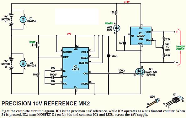
However I have found the reading from different meters to have a wide variation
and I don't know if the fault develops over a period of time or due to the
inherent inaccuracy of the meter when purchased.
Instead of spending money on a complex project, you can simply use a few mercury
cells or silver oxide cells to determine the accuracy of a reading.
Fresh mercury cells have a terminal voltage very close to 1.356v at 20�C and
silver oxide cells have a voltage very close to 1.55v
You can use 2 or more of these in series to get a reading of say about 5v and check
your meter accurately for a few dollars. You can then use the cells in a piece
of equipment and not waste them.
The other problem with the circuit is this: the 4541 is connected to the battery
AT ALL TIMES and the battery goes flat after a few months !![]()
http://hobbyelectron.blogspot.com.au/2012/03/automatic-street-light-controller.html
Why use a 2200u for 100mA circuit ????
Why have a transistor buffer when the 555 will deliver 100mA !!!!
Why is C3 50v when the voltage will be 0.7v MAXIMUM !!!!
Why use a 7809 regulator when a 9v zener diode can be used.
VR1 is not a variable resistor. VR is used for a VARIABLE RESISTOR.
![]()
![]()
Here's another circuit that may not / does not work:
The thermistor resistance value is 110 ohms. Suppose the resistance
becomes 90 ohms after heating the thermistor. Then the voltage across
one resistor of the voltage divider circuit equals the ratio of that resistor�s
value and the sum of resistances of the voltage across the series combination.
This is the concept of a voltage divider. The final output voltage of the voltage
divider circuit is now applied to the NPN transistor (BC548) through the base
resistor (3.3k ohms). The emitter has a 4v7 zener diode.
Emitter voltage is maintained at 4.7volts via the zener diode. This
voltage is used to compare voltage. Transistor conducts when base voltage is
greater than the emitter voltage. Transistor conducts if it gets more than
4.7volt of base voltage. Then the circuit is completed through buzzer and it
gives sound.
The above statement is correct, but the voltage on the base has to be 4.7v plus
0.6v = 5.3v.
To get 5.3v on the join of the two resistors, means the thermistor has to drop
to 70R.
At 5.3v, the transistor just turned ON and the thermistor will have to go to a
lower resistance to allow the transistor to deliver CURRENT to the buzzer.
It will be difficult for the circuit to work successfully.
![]()
Here's another circuit that may not / does not work:
The output of the op-amp will be a maximum of 8.5v.
The voltage divider will drop this to 4v.
The emitter will be 3.4v The piezo buzzer will not be very loud
!! But some buzzers produce an output when the supply is 5v, so get a 5v
buzzer and remove R4. ![]()
The 6v input voltage will NEVER charge a 6v battery.
The BC547 transistor and 180 ohm resistor will simply add a small load to the 6v
(should be about 9v) supply.
It will have NO effect on adjusting the current to the battery.
This is another circuit that DOES NOT WORK. It has never been built or tested.
![]()
Another circuit that has never been tested.
![]()

The project does not provide information for the program for the PIC chip, so it
cannot be constructed.
![]()
The op-amp is not needed.
The two diodes are not needed.
The circuit can be simplified to a voltage-divider that detects the upper
voltage and activates the relay.
This is how the circuit can be designed:
![]()
It produces a tone when a strong wind blows across a piezo element.
It has been designed by some who knows very little about electronics, but let's
look at the design-faults.
Firstly, the gain of a transistor is about 70 - 100 so you only need 3
transistors to convert the 10mV to about 2v.
There is no CURRENT REQUIREMENT because pin 4 of the 555 is a high impedance
pin.
You only need to raise pin 4 two volts for the chip to turn ON - it does
not have to rise to 9v. Pin 4 has to drop to 0.5v to turn the chip OFF. But when
it is turned OFF, the chip still takes 10mA and that's one of the reasons why a
555 should not be used.
The piezo element is equivalent to 22n, so C1 (1n) is NOT needed.
The piezo element is a very high impedance device and the 1M base-bias resistor
is effectively acting as a LOAD. This is because the positive and negative rails
are technically connected together as far a signal is concerned, due to the
battery having a low impedance and the 100u across the rails.
If the 1M is changed to 2M2, the circuit becomes more sensitive.
The next important point to understand is the fact that the transistor
effectively multiplies the collector resistor by 100 (the gain of the
transistor) and if this resistor is increased to 47k, the stage will be more
sensitive.
This means we can eliminate the second transistor. (actually the third
transistor)
The fourth transistor is not needed as we can charge the 10u from the second
transistor.
This electrolytic can be taken directly to pin 4 as pin 4 is a high impedance
pin and the chip will turn ON.
Charging the 10u is not a high impedance operation, but we are using the TIME
DELAY in charging it, to produce a delay before the 555 turns ON.
The 6 transistor circuit can be reduced to 2 or 3 transistors.
Two more components that show the designer has no understanding of electronics:
The 10R resistor R8 is not needed.
The 470R R13 is a low value across a high impedance pin. This can be
increased to 1M.
This circuit shows a complete lack of understanding of IMPEDANCE VALUES.
Impedance values are effectively resistance values and both the detecting device
and pin 4 are high impedance.
The surrounding circuit should also be high impedance. That's the skill of
being a design-engineer.
Read the article:
THE
TRANSISTOR AMPLIFIER.
![]()
The actual project does not connected the neutral lead to ground (earth) and the
circuit diagram is INCORRECT.
If you connect the neutral lead to the earth lead on a project, the fuse will
blow if the active and neutral are swapped.
They may get swapped if you use an extension lead that has been wired
incorrectly.
The circuit will deliver about 35mA. The LED will take 10mA.
![]()
MUSEUM ALARM
Why have a circuit taking power all the time. ????
You can get reed switches that are change-over or have two contacts that are
separate when a magnet is present and make contact when the magnet is removed.
This way the circuit takes NO POWER.
What is the purpose of R1. ?? The reset line is high impedance and does
not need a 10k resistor.
Using Q7 and Q9 to blink the LED will put a reverse voltage on the LED. Use one
output and 0v.
The battery will be flat in a few months.
![]()

But is just another over-designed piece of RUBBISH and none of the 56 replies
from the readers had any understanding of the dangers of this project.
The circuit is classified as a CONSTANT CURRENT CIRCUIT. What is the purpose of
the transistor???? It does nothing AT ALL.
I can't blame Raju Baddi for this rubbish circuit as none of the readers (except
3) realised the dangers of this type of supply.
There are so many mistakes with this circuit, that is should never be built.
Here are 5 faults:
A 100R to 220R safety resistor should be included in the AC line.
The earth symbol should be removed.
The circuit is overly complex.
The circuit will deliver 7mA for each 100n of the X2 rated AC capacitor for a
240v mains.
This is all that is required and not all the rigmarole of a formula.
The circuit will not drive a 555 using a 0.068u as the 555 requires 10mA! There
is nothing left to drive the LED
Transformerless circuits like this are very dangerous and BANNED in Australia.
There is no point in using a 2N3053 when Rb is only 1 watt!
There is no point in using zener Vz when a current limiting resistor is also
employed.
The Engwish used in the text is undecipherable. What does: "Cac constantly
drains after the bridge" mean????
Just a bad circuit with NO technical expertise behind it.
This is my reply to the project on the Network website:
This is an extremely dangerous circuit.
All the comments such as: "I'm a little surprised to see so many comments that
call this type of reactive supply unsafe " are quite ABSURD.
As soon as the wires to the mains are reversed, the device being charged is at a potential of
180v or 345v.
There is no such thing as 120v or 240v (This is another fact that all readers
have overlooked). The power supply may be insulated, but no mobile phone or toy
is insulated to this degree.
![]()
Remove the transistor and connect the LED between the lower lead of R5 and the
0v rail.
![]()
What is a 3-pin "IR" ???? The text says it is an
IR transistor.
Pin 4 of the 555 is not connected.
No 330R current limiting resistors on the LEDs.
The diagram is NOT a circuit diagram. It is very difficult to work out
what is happening if you don't draw a CIRCUIT DIAGRAM.
The 4017 will never "clock" with a LED on the clock-line.
Just another JUNK circuit - not to be constructed. ![]()
Here's a poorly designed circuit from Velleman. It is over-designed. You
don't need to bias the transistors into their "linear range" for a simple
amplification requirement. This is not an AUDIO AMPLIFIER. It is just a SIGNAL
AMPLIFIER.
It also has a slight delay to create after-fade for the LEDs.
All the unnecessary components have been removed.
This project show the lack of circuit-understanding on the part of Velleman
engineers.
The whole secret of designing a circuit is to use the least number of components
and avoid as many mistakes as possible.
The original circuit will stop working at 7v and the third 100n should be
increased to 1u to 10u as the current increases through the circuit.
The 100k on the base of the base of the 4th transistor is far too high. The 47R
as the current limit resistor shows a complete lack of understanding "head-room"
for strings of LEDs.
The circuit can be reduced to 3 transistors and fewer components.
The original circuit did not take full advantage of the gain of each stage and
the revised circuit is just as sensitive with 3 stages:
The first stage in the circuit is really the microphone and 10k as the
microphone contains a FET transistor and this is effectively an amplifying
component.
The 10k resistor is far too low for a microphone in a normal audio amplifier as
our electret microphones need 47k current limiting resistor for 9v. When using
10k, the output is far too loud and completely distorted because the 10k is
allowing far too much current to flow through the microphone .
For this circuit we only need a signal and the quality of the signal is not
important.
The next stage is a self biased transistor with a gain of about 70 to 100. It
does not matter what type of transistor you put in this stage. The gain of most
transistors is above 100 but the 1M between the base and collector is
effectively a feedback resistor that reduces the gain.
The output is taken to another self-biased stage with the biasing on the base creating
less than 0.6v so the transistor is NOT TURNED ON.
The actual voltage is about 400mV. This means the signal coming from the
microphone and through the first amplifying transistor has to be about
300mV or more, to increase the voltage on the base to above 600mV to turn the transistor
ON. The slightest noise produces this type of signal.
Once the second transistor is turned ON, it pulls the base of the third
transistor low via the 1k resistor and this allows it to illuminate the LEDs.
The circuit consumes less than 0.5mA when "sitting around" - this is called the
QUIESCENT STATE. ![]()
Look at the blurb T. K Hareendran says about himself and yet he cannot draw a bridge rectifier circuit.
Almost all his circuits have faults. He knows practically NOTHING about
electronics and you can see some of his other faults in previous pages.
Here is his blurb: T.K.HAREENDRAN I am
an Internationally Certified/Technically Qualified Professional Freelance
electronics circuit designer, technical writer, columnist, consultant, domain
expert&trainer based in Kadakkal (Kollam-Kerala)India.My works have appeared in
leading print&online media, in India and abroad, since 1988.I write on varied
topics including Electronics, Computer, Technology, Business, Healthcare, Astrology
and Life, etc. My articles have appeared/scheduled to be appeared in Electronics
For You(I), Elektor Electronics(UK), Silicon Chip(AU), Nuts&Volts(UK), Everyday
Practical Electronics(UK), Electronics Maker(I), Electronic
Design(UK), Infokairali(I), Electronics Cable Chip(I), Television For
You(I), Electronics Hobby Circuits(I), Malayala
Manorama(I), Mathrubhumi(I), Deshabhimani(I), Balabhumi(I), Mangalam(I), Labour
India (I), Kunkumam(I), Hasyakairali (I), Techvidya(I), Cartoon plus(I), Madhyamam
(I) and several other publications. I have authored a number of best seller
books, e-books, electronics/computer repair manuals and interactive tutorial CD/DVDs. One
of my best seller print in Malayalam is "Electronics"- Published by
Infokairali(I). Follow me on http://twitter.com/tkhareendran
T.K.HAREENDRAN I am
an Internationally Certified/Technically Qualified Professional Freelance
electronics circuit designer, technical writer, columnist, consultant, domain
expert&trainer based in Kadakkal (Kollam-Kerala)India.My works have appeared in
leading print&online media, in India and abroad, since 1988.I write on varied
topics including Electronics, Computer, Technology, Business, Healthcare, Astrology
and Life, etc. My articles have appeared/scheduled to be appeared in Electronics
For You(I), Elektor Electronics(UK), Silicon Chip(AU), Nuts&Volts(UK), Everyday
Practical Electronics(UK), Electronics Maker(I), Electronic
Design(UK), Infokairali(I), Electronics Cable Chip(I), Television For
You(I), Electronics Hobby Circuits(I), Malayala
Manorama(I), Mathrubhumi(I), Deshabhimani(I), Balabhumi(I), Mangalam(I), Labour
India (I), Kunkumam(I), Hasyakairali (I), Techvidya(I), Cartoon plus(I), Madhyamam
(I) and several other publications. I have authored a number of best seller
books, e-books, electronics/computer repair manuals and interactive tutorial CD/DVDs. One
of my best seller print in Malayalam is "Electronics"- Published by
Infokairali(I). Follow me on http://twitter.com/tkhareendran
The circuit above is just a MESS and no-one will be able to see the mistake
because of the way it is drawn.
Here's an explanation why the circuit WILL NOT WORK.
Firstly we draw the circuit with the "L" wire producing a POSITIVE waveform:
I have removed all the unnecessary writing and components that are not
involved.
At this point in time I do not know if the circuit will work, so let's go
through the situation.
Basically the current runs around the outside with the resistor, capacitor,
zener, electrolytic and lower diode.
The 100u would normally see 345v across it but ZD2 reduces the voltage to 12v.
This means the maximum voltage produce by the circuit is 12v across ZD2. If we
now have ZD1 removing 12v from the "supply" the electrolytic will see ZERO VOLTS
!!!
Here is the circuit:
But ZD1 limits the voltage across the 100u to 12v and if ZD2 removes 12v from
this "supply" there is no voltage available to charge the 100u !!
It's a simple as that.
But to see these faults, you MUST draw the circuit in the CONVENTIONAL WAY so
you can "SEE" what is happening. I had no idea the circuit would not work until
I re-drew it.
I am not "Mr Marvel Man." I cannot see through buildings or see how a circuit
works unless it is drawn correctly.
But just seeing a project by T. K Hareendran makes me look closely and analyse
things thoroughly. His junk circuits can be seen everywhere.
Here is his reply:
Writers like this should be exposed for their total lack of
understanding electronics. Even when you explain why a circuit does not work,
they fail to comprehend the facts.
He has now provided a correct circuit. But no mention of the mess he
produced in the magazine, messing up the readers who will try to get the circuit
working.
I wouldn't understand electronics either if I produced jumbled circuits.
Here is the correct layout for the circuit so you can understand what is
happening:
There is always one zener across the supply to create a maximum of about 12v
(actually 12v - 0.7v). If you draw a circuit like this, you CANNOT make a
mistake. ![]()
The combined resistance of the 4 pots is 117R. The voltage at the join of the
270R and the 4 pots will be
(5 / 387) x 117 = 1.51v The LM385 is an accurate voltage
source that produces 2.5v. But ONLY 1.51v is available !!!!
Another untried, untested, circuit from: Petre tzv. Petrov.
Electronics For You never tests anything and most of the circuits they
publish in their magazine DO NOT WORK or are too complex for the required task.
![]()
Here's another circuit from
Electronics For You
June 2015, that does not work:
The 0.1u will be charged.
To activate the 555, pin 2 must be taken LOW and for 12v supply, this will be
less than 4v.
In other words the 100n must discharge via the 10k and then the transistor must
pull the 100n to a low voltage (before it gets charged again) so pin 2 activates
the 555.
This is a very MESSY situation and the circuit is poorly designed.
Firstly the piezo has to work against the 2M2 to turn off the transistor. Then
the 100n has to work against the 10k to pull pin 2 low before it gets charged
via the 10k.
I would consider this circuit to be very unreliable in picking up the short
sharp pulse of a breaking window.
In addition, if the pot is turned fully clockwise, pin 7 will create a
short-circuit and damage the pot.
![]()
The impedance of 100p at 1MHz is 1k6 but if little or no current flows through
the capacitor, little or no voltage will be dropped across it and thus it will
produce little or no loss. So, any value above 1n is unnecessary.
It just shows the lack of understanding to use 220n. And of course, D. Mohan
KUMAR has NO electronics understanding and produces a myriad of JUNK circuits
that either do no work or use incorrect value components.
That's why it is so difficult for Indian students to get a good grounding in
electronics, when you have magazines and "Professors" who publish rubbish
circuits. ![]()
It may turn ON due to the 4u7 slowing down the rise of the "k" lead but this is
not the correct way to operate a thyristor.
Secondly, since we have turned ON the thyristor, we can use it to turn on the
relay. So why use a FET to drive the relay ??
Where are you going to buy a AC125 germanium transistor?
![]()
Why connect the speaker to 3v - 0.6v = 2.4v ???
Push the CALL BELL switch. What is it going to do??? T3 will turn ON with
2.4v on the base and 1.8v on the emitter. The UM66 and speaker will see 1.6v
!!!!
Push the TIMER ON + CALL BELL switch and the base of T3 will see 17v and the
UM66 will see 17v via 330R - It must not see more than 3v. What do you
think will happen !!!!!!! There are other faults such as supplying
more than 18v to the CD4060 and what's the purpose of R8 ? (2k2).
Just an untried, untested circuit from SURESH KUMAR K.B.
![]()
Here is a circuit that needs careful attention.
There is no information on the sensor. In fact there is almost
NOTHING you can connect to the sensor connections.
If you connect a switch to the sensor connections, the transistor will BLOW UP
!!! The current through the base-emitter junction will damage the
transistor.
If you put your finger on the sensor pads, the transistor will not turn on
sufficiently for the amplifier to drive the speaker.
In fact there is nothing you can connect to the sensor. Who designed
the circuit ????
![]()
Here's another junk circuit from D. Mohan KUMAR

Two major faults with the circuit. Charging via the solar panel
just needs a 11v zener connected to the transistor.
The output of the 14v transformer will be 20v DC and a 100R resistor is needed
to prevent the current rising to more than 500mA.
The corrected circuit is:
Electricity is so cheap. I don't see the point in buying a 10watt panel when the battery can be charged from the mains. 10 watts x 8 hours x 360 = $6.00 per year !!
![]()
Here's another untried, untested, "dreamed-up" circuit from "Professor" D. Mohan KUMAR:
When a solar panel does not received any illumination, the
output becomes ZERO but the resistance (impedance) across the terminals does not
become a low resistance. It is effectively a very HIGH resistance.
The 1N4007 prevents the voltage from the battery entering the solar panel and
delivering a small current. But this current is very small and when the battery
voltage is less than the voltage that is capable of being generated by the panel, this current becomes
EXTREMELY SMALL. Each 0.6v generated by the panel is derived from a sol cell and
when a number of these are in series and not producing a voltage, the effective
resistance to an incoming voltage is very high until the incoming voltage
overcomes the "junction resistance" produced by each cell.
In the circuit above, the 4v battery was TESTED and it delivered NO CURRENT into
a 5v or 6v solar panel.
This means NO CURRENT will flow in the 4k7 when the panel is not illuminated.
This mans the circuit will NOT turn ON during the night.
The circuit needs a 1k across the panel and the 4k7 needs to be 470R
as shown in red.
This will allow about 3mA to flow in the base and if the transistor has a gain
of 100, about 300mA will flow in the LED.
The original circuit WILL NEVER WORK.
![]()
Here is a homework question from an instructor:
The power rating and the zener voltage of the two zener diodes
(Z1 & Z2) used in the circuit are 1 watt & 10v and 0.6 watt & 6v. Minimum zener
current needed for the satisfactory operation of both zener diodes is 2 mA.
Find the range of RL values in which the circuit can be used as a voltage
regulator.
The circuit is totally impractical and, as you will see, completely unworkable.
We start by seeing the 500R has 90v across it and this means 90/500 = 180mA will
flow.
180mA will flow through the 10v zener and this means 10 x 0.18 watts will
be lost in the zener. This is 1.8 watts and the zener is only a 1 watt device.
It will BLOW UP.
Let's pretend it is not damaged.
The voltage across the 300R resistor is 10v minus 6v = 4v.
The current through the 300R resistor is 4/300 = 13.3mA
We can take 11.3mA for RL.
The resistance of RL = 6/.013 = 462 ohms.
RL can be 462 ohms or higher.
This explanation was removed from the FORUM because they do not like homework to
be answered.
But after 2 weeks no-one provided any help and the value of the FORUM is
WORTHLESS.
The fastest way to learn any subject is to be given all the answers.
You then have a choice of looking at part of the answer to see how you are
progressing.
Obviously those in charge of the electronics forum have no idea how to teach.
![]()
A poor design by Robert Penfold.
This is not a Level Shifter but a Level Shifter AND Inverter
All that is needed is a set of 3 diodes to remove 1.8v from the 5v line to get 3.2v:
This circuit provides LEVEL SHIFT without INVERSION
Figure 2 can be improved by designing a circuit that shifts the level but does not invert:
![]()
PIC Books for immediate FAST download without any tricks or traps:
http://pictutorials.com/PIC_books.htm
![]()
LED LAMP
Two fault with this circuit. How is the 0.22u capacitor
discharged? The zener should connect to the capacitor.
The 0.22u will deliver a maximum of 7mA. That's 2mA for each LED. How
bright will they be???
Why use a zener when the capacitor-fed power supply is a constant current
supply.
What is the point of adding the 4R7 ??
Just another useless circuit from Electronics For You magazine.
![]()
Here's another stupid circuit from Electronics For You.
The alarm sounds 30 seconds after the thief has broken the wire across the door.
The circuit takes 5mA while sitting around. The battery will be
flat in a few months.
The circuit could be re-designed to take a few microamps by freezing the
oscillator of the chip.
Why sound the alarm after 30 seconds ??? The circuit is
useless !!!!
![]()
BATTERY PROTECTOR
The life of a battery dramatically reduces when it is discharged below the minimum recommended voltage.
This circuit switched off the load when the battery falls to a certain voltage.
The
circuit is too complex. It just needs a zener diode and a relay. You can include
an ordinary diode if you want to decrease the set-voltage by 0.6v.
![]()
Not a well-designed circuit.
The supply voltage to the IC is 9v. The voltage on the inputs to the gates
should be close to 9v to guarantee the IC registering a HIGH.
The TSOP1738 takes a few milliamp and the voltage on pin 2 will be less than 5v.
The voltage on pin 13 will also be less than 5v and it is getting very close to
the point where the chip will not detect the voltage as a HIGH. A chip really
need 66% of rail voltage (nearly6v in this case) and less than 5v is going to be
doubtful.
Another circuit from Electronics For You, designed by a reader who has
little or no understanding of electronics. Anyone building this circuit would
have a hard time detecting why it does not work.
![]()
POWER SUPPLY
This is a very BAD and DANGEROUS Power Supply because the output immediately rises to 12v when the switch is changed from one position to the next because the contacts become "open" during the switching-action and the power supply "thinks" you have chosen "12v."
![]()
DICE
Here's a faulty circuit from Velleman
If you go through the logic of the outputs of the CD4024 chip, you will find the
sequence is 1, 2, 3, 2, 3, 4, 5, 6.
This is because there are 8 cycles of the first three outputs as 0,0,0 produces
a HIGH from the transistor to turn on 6 LEDs and then there are 7 more
combinations.
I have never seen a worse DICE circuit. Imagine if a player selected 2 or 3 to
WIN.
He would "scoop the pools" and walk away with the jackpot !!
Reply from kit supplier:
Yes, the kit is not a true random number generator, or even a pseudo-random number generator. It is meant only to simulate dice rolls. It has virtually no capacity to predict randomness.
My reply:
Why don't you say on the kit page that 2 and 3 will appear more often than the
other numbers??
It probably doesn't matter for some board games, but if you are trying to make a
DISTRIBUTION CURVE to test the randomness of electronics, the circuit will
produce a big mistake.
![]()
CAR ALARM
Here is a
Velleman Car Alarm. It relies on the fact that the voltage on the
"electrical system" is slightly higher when the car is running due to the fact
that the alternator is charging the battery.
The whole circuit can be simplified to a transistor and RED flashing LED:
The two circuits above are an attempt to make it easier to detect the
small change in voltage on the electrical system (across the battery). The
second circuit puts a larger voltage-change across the 10k mini trim pot.
The skill in designing a circuit is to make it as simple as
possible. Anyone can use a quad op-amp and 50 other components to flash a LED,
but if you expect to have any chance of retaining your job, you need to keep
things as simple as possible.
Otherwise the opposition will come out with a simpler circuit.
Here is another disastrous circuit from Swagatam.
The 100k and 10k resistors form a voltage divider.
If the Mains voltage is 240v, the peak will be about 300v and you will get about
30v at the join as the two resistors (as they have a ten-to-one ratio). The 24v zener
will reduce this to 24v.
The current delivered to the combination will be about 3mA as 300v into a 100k
resistor will deliver about 3mA.
24v across a 10k resistor will pass 2.4mA through the resistor. That leaves
0.6mA for the zener.
Now, here's the problem.
How much current can you "get out of" the 10k resistor ???
The 10k resistor in this circuit is not like any ordinary 10k resistor with 24v
across it.
This 10k comes as part of a voltage-divider and only a maximum of 3mA is
available.
To work out what happens is VERY COMPLEX but we will simplify the problem by
using different values of resistance across the 10k and see what happens.
If you put a 10k resistor across the pot, the resistance will be 5k and we have
to work out the voltage divider situation again. 100k and 5k will produce about
15v across the combination - that's because about 3v is developed across each 1k
of resistance).
Immediately you can see the 24v has dropped to 15v and the zener regulator has
lost its stability. THIS IS THE FIRST PROBLEM WITH THE CIRCUIT.
About 3mA will pass through the two 10k's in parallel and each 10k will pass 1.5mA.
If we now remove the 10k resistor and try to deliver the 1.5mA to the
transistor, here's what happens:
The transistor has a gain of 50 and this means it will deliver 50 x 1.5 = 75mA.
Another example:
If you put 1k across the 10k pot, about 3mA will flow in the 1k but the voltage
across it will about 2v.
The whole circuit is absurd because if you want 3mA, YOU CANNOT GET IT
because the voltage keeps dropping to ZERO !!!!
We have simply shown the circuit DOES NOT WORK and if SWAGMAN had built the
circuit before making a fool of himself, he would have saved a lot of experimenters
being frustrated.
Do not describe anything that has not actually been built, tested and used for a
long period of time.
You need to try it with all sorts of load, all sorts of capacitors, all sorts of
transistors to be sure it does not fail.
Very few people can "see" the failings in a design by looking at the circuit but
these pages are designed to make you aware that this skill CAN BE LEARNED.
![]()
ALARM
Here's an alarm circuit with very poor design-features.
A 1k resistor on the input of an op-amp is not going to have any effect because
the input is very high impedance and thus very little current will flow through
the resistor and thus very voltage will develop across it.
The same applies to the LDR connected to the other input. The input pin is just
like connecting the LDR to a nail hammered into a piece of wood. It is called a
"floating terminal" or a "high-impedance pin."
The op-amp will detect a change in voltage on either of the inputs but they are
just like two nails hammered into a piece of wood. They effectively "don't go
anywhere."
If you want the voltage to change on either pin, you must create this change via
a VOLTAGE DIVIDER.
If you have a 10k resistor from a 9v supply connected to a nail, the voltage on
the nail will be 9v. If you increase the resistor to 1M, the voltage on the nail
will still be 9v. Obviously you have to measure the voltage with a very high
impedance meter, but it will be 9v.
The input to an op-amp is just like a nail. It does not allow any current to
flow though the resistor and thus no voltage-drop is produced across the
resistor.
Thus the change in resistance of the LDR will not change the voltage on the
input of the op-amp.
In reality, some op-amps might draw a very small current and the voltage will
change, but this is not something you can rely on when designing a circuit.
The third fault is the reset button connected to pin 15.
This pin is also connected to pin 4 and at the moment the chip is producing a
LOW on pin 4.
It is not a good design to connect an output of a chip directly to the positive
rail when it is in a LOW condition. This is called a "conflict" and even though
it might not damage the output, it shows poor-design.
The circuit is obviously not designed by a knowledgeable person.
![]()
Here a book with 100 simple projects. They have been copied from different magazines and some circuits have faults, but it's a good book for ideas: MINI ELECTRONIC PROJECTS

![]()
UNIPOLAR MOTOR
This discussion is to show why it is important to analyse each
and every component in a circuit and decide if it is not needed.
I have previously shows the fault in a circuit that had 3 extra components and
if you are making 100,000 units, this can represent a considerable cost.
The middle IC is a quad OR gate and the output of the 4017 drives A, B, C, D
then A, B, C, D HIGH The middle IC can be removed and the first 4 outputs of the
4017 taken directly to the ULN2003 IC and after the 4th output does HIGH, the
4017 is reset and the cycle repeats.
I don't think the rest of the circuit works efficiently anyway, but that is for
another discussion.
![]()
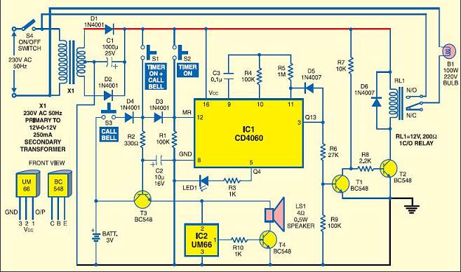
DOORBELL
Here's a lesson how NOT to design a circuit.
Firstly, the bell switch is in the 230v line. No bell-switch is designed
for 230v.It is designed for 12v.
What is the point in turning ON the 5v supply to the IC via a relay? When the
switch is pressed, all the components can be activated via very simply
circuitry.
The chip is designed for 3.5v. The voltage divider will produce a maximum
of 2.5v
But when you look at the output, you see the output-to-ground is 560 ohm and
because the supply is derived via a voltage divider, the 2.5v will be reduced
further to about 1.7v MAX.
The voltage divider for the chip is classified as a HIGH IMPEDANCE SOURCE
because any load on the output up to about 4k7 will reduce the supply
noticeably.
The 5v regulator is not needed. The 3.5v can be derived from the 12v regulator
using 100R and 39R resistors.
![]()
TURNING INDICATOR

Anjali Sethiya
When you on the switch S1 for indicator of right or left side
this will cause the voltage drop across resistor R1. This will drive the
transistor T2 into conduction. And Transistor T1 also conducts which energise
the relay and the buzzer connected to it start sounding. If you want you can
connect your car indicator light lamp in place of LED's.
Take care while using the value of resistor R1. It should be chosen according to
requirement like if you are using LED its value may vary from 100 ohms to 1 K
ohms.
Can you see the BIG MISTAKE?
Transistor T1 is ON all the time and is turned OFF when the LEDs are
illuminated.
The turning LEDs should FLASH. The circuit does NOT DO THIS.
The LEDs are turned ON via the 4k7 resistor. They only get 2mA !!!!
R1 should be 100R to 470R NOT 100k.
This is a useless circuit. It is too complex and does not flash the LEDs.
![]()
Let me explain why this is the worst circuit on the internet. Not only has it been designed by
T.K.HAREENDRAN
The circuit starts by connecting the battery and the 100n prevents voltage appearing on the base of the base of the first transistor.
This means the first transistor is not turned ON and both T2 and T3 are not turned ON.
When the tilt sensor allows current to flow into the base of the first transistor, it is turned ON
The tilt sensor will only turn it on a small amount and will not damage the transistor.
But as the transistor turns ON, a voltage develops across the 10k resistor and this allows T2 to start to turn ON.
It turns ON with a small amount of current into the base but 100 times more current flows in the collector-emitter leads and this current begins to turn on T1.
T1 now receives 100 times more base current and this action continues until both transistors are fully turned ON.
There is no current limiting resistor in the circuit and both transistors WILL BLOW UP.
At the same time T3 is turned on FULLY and it has no current-limiting resistor and it will BLOW UP TOO.
This makes it with worst circuit on the web.
![]()
DOOR ALARM
When will
Electronics For You Magazine
stop publishing JUNK circuits?
If pin 3 is at 0v, the voltage on the base of the PNP transistor will be 0v. The
emitter will be 0.6v. This 0.6v will be passed to the NPN transistor and it will
be turned ON all the time.
The BC557 is an emitter-follower and the emitter is never less than 0.6v and the
piezo will never turn OFF. This is simple, obvious, basic electronics. EFY
doesn't have any technical staff to see this fault. And yet they are running an
electronics magazine in India - a country that says they are
up with the
latest technology!!!
![]()
The 7805 regulators are in CONSTANT CURRENT or CURRENT LIMIT
mode and this means the output will rise and rise and rise until it reaches the
input voltage (less 3v). This will happen when the battery is removed and on the
output are two zeners and a LED.
These three components create a fixed voltage across them and the voltage cannot
rise above 6.8v + 6.8v + 1.7v = 14.3v.
The 7805 is capable of delivering 1amp and the circuit reduces this current but
it is still sufficient to damage the LED and when the battery is removed
POOF!
The LED blows UP !!
No-one at
Electronics For You Magazine
understands electronics and all the readers are delivered this sort of rubbish.
![]()
DOG KENNEL LIGHT
The above circuit from
Electronics For You Magazine
DOES NOT WORK. The chips requires a minimum of 3v. It has almost no capability
at 2.4v.
What is the purpose of R1??
What is the purpose of R4 ??
R4 is called a SENSE RESISTOR and it detects a small voltage across it when a
high current flows. It has a very low value so it does not
reduce the voltage to other parts of the circuit. In other words, there must be
a LOAD on the end of the resistor.
In this circuit the "sense" input is HIGH IMPEDANCE and almost no current flows
though the 0.22R. It is pointless including this resistor in the circuit.
T.K.HAREENDRAN
has no idea about impedance-values and doesn't know how to design a circuit FOR
NUTS.
Can you imagine buying all these exotic components for a DOG KENNEL LIGHT ! What
does a dog need a light for? Does he read in bed????
The circuit
can be simplified to:
The secret of a good design is to keep everything simple and use readily-available components.
Here is a circuit sent in by a reader:
If the 10k mini trim-pots are turned fully clockwise, the very
small resistance between one end and the wiper will cause a very high current to
flow and they will be burnt out. The second diagram shows how the trim-pots
should be connected to prevent any problem.
A 1k safety resistor can be added to the trim-pot connected to the LDR if you
have a type that produces a very small resistance when detecting very bright
light.
![]()
DOORBELL
Another disaster by T.K.HAREENDRAN
The LED inside the opto-coupler will see 250v or more as a
reverse voltage and BLOW UP!
No current limiting resistor for the white LED.
![]()
CAR
LED LIGHTAnother disaster by T.K.HAREENDRAN
This circuit can be replaced with a single resistor!!!!!!!
Before you start to design ANYTHING. Look on the web for
circuits and see what has been done by PROFESSIONAL ELECTRONICS ENGINEERS.
This applies to ANYONE designing ANYTHING.
It will save a lot of embarrassment.
It is obvious that T.K.HAREENDRAN does not have a
clue about designing a circuit and yet he keeps putting his rubbish into
magazines and on the web.
And he keeps annoying me with rude emails about how incompetent I am !!!
I may be incompetent but no-one has emailed me to explain where my incompetency
is or where I am wrong.
Until that time comes, you will just have to believe these corrections are
factual.
![]()
SOLAR CHARGER
Another disaster by T.K.HAREENDRAN
You don't need the LM317. The small solar panel will not
overcharge the battery. But if you get more than 5 hours sunlight, you can add a
22R to 47R in series with the solar panel to reduce the charge-current.
The solar panel needs to produce 4v plus 1.2v called the "floating charge"
produced by the battery when it is being charged, plus a small voltage dropped
across the 8R2 (1v) plus 2.5v dropped across the LM317. This means the
solar panel must produce more than 8.7v so that a current will flow.
Remember this: At 8.7v NO CURRENT will flow because the solar panel is producing
exactly the same amount of voltage that is "developed" by the circuit. It
is a bit like connecting a 9v battery to another 9v battery. No current will
flow from one battery to the other because the voltages are the same.
If the solar panel produces 9v, a current will flow according to the "overhead
voltage" of 0.3v. The amount of current cannot be worked out because this
current flows through the cells of the solar panel and these cells have a
resistance or "impedance" that will limit the current.
So, the solar panel has to produce A LOT MORE VOLTAGE so that a current will
flow.
Simply specifying a 6v solar panel is quiet useless. The solar panel needs to
produce more than 9v to charge a 4v battery, using this circuit!!!!
The second problem with the circuit is this: The LEDs are connected directly
across the 4v battery. White LEDs have a characteristic voltage of 3.2v to 3.6v.
They will BLOW UP when connected to 4v !!!!
![]()
You will lean MORE through these discussions than any text book.
How do you think I became so clever? I fixed thousands of faults in
electronic products and found out how NOT TO DESIGN A CIRCUIT. I found out
thousands of things that NO TEXT BOOK ever explained.
![]()
Page 1
Page 2
Page 3
Page 4
Page 5
Page 6
Page 7
Page 8
Page 9
Page 10
Page 11
Page 12
Page 13
Page 14
Page 15
Page 16
Page 17
Page 18
Page 19
Page 20
Page 21
Page 22
Page 23
Page 25
Page 26
Page 27
Page 28