SPOT
Page 1
Page 2
Page 3
Page 4
Page 5
Page 6
Page 7
Page 8
Page 9
A recent visitor in an electronics forum asked: "Is electronics dying?"
Talking Electronics has produced a number of pieces of test gear to help
in designing circuits.
Talking Electronics website concentrates on explaining the BASICS of
electronics.
One of the brilliant ideas introduced some 30 years ago was the concept
of a COMPUTER SWAP-MEET.
INDIA
Here's a very simple way to work out the voltage you will get across the
32R load (32R speaker).
Here is
The kit costs $2.00 from Hong Kong !!!!!!
4 CHANNEL TO 2 OUTPUTS
It
does not let you know when no input is present and is very complex in
design.
Picbuster replied:
The original circuit is so
messy that I could not work out how it worked. It has been re-drawn and
now you can see the mistakes. The 100k pot can be turned to zero
ohms and when the switch is pressed, the transistor will be damaged. The
SCR is IRF530n and its gate voltage is about 2v to 4v. It
may work at 3v.
CLAP SWITCH - another Clap Switch !!
This is a badly designed circuit because the mic does not have a load
resistor and it is effectively across the 6v to 9v supply.
The electret mic needs an operating current of less than 1mA and the
original circuit did not have a load resistor to limit the current.
TRAFFIC LIGHTS
Another badly designed circuit from the same website.
Hi Colin
Here's a SET / RESET circuit made with relays.
TSOP 1738
THE MISTAKES!
Page 27
Page 10
Page 11
Page 12
Page 13
Page 14
Page 15
Page 16
Page 17
Page 18
Page 19
Page 20
Page 21
Page 22
Page 23
Page 24
Page 25
Page 26
Page 28
Page 29
Page 30
![]()
We all know electronics is not dying because everything you hold in your
hands is based on electronics.
But the desire to learn electronics - in the hope of making it a career
- has changed enormously.
50 years ago you could become a technician - a radio technician,
communications engineer, 2-way radio installer, repairer, CB radio
stockist, radio station technician, car
radio installer or repairman. You could design and manufacture amplifiers for music, guitar, schools,
offices. Install 2-way radios for taxis. Service black and white TV's and colour
TV's.
The field and market was enormous.
Servicemen worked from 8 in the
morning to 11 at night, 7 days a week. Everyone wanted amplifiers, TV's
and sound systems.
Then the Japanese and Chinese came in with products that were cheaper
than the cost of a repair.
And servicing went out the window.
Now, nothing gets serviced or repaired.
That's what changed the industry.
In addition, all manufacturing went overseas.
What are we left with?
Just a few sales.
And this can be done by juniors, just out of school, with 2 weeks
training.
You don't need anyone with an electronics background as nothing will be
pulled-apart, fixed or serviced.
So, what about design?
This has gone overseas too.
Even though the Chinese had no mechanical or technical ability, some 50
years ago (you just have to look at their farm machinery and cars etc) they sent their students overseas to acquire
the latest technology in EVERY field and are now at the forefront of
advanced designs.
Even though some of their designs are clumsy and faulty, they learn from
their mistakes and after the third or fourth generation, their product is
fully acceptable.
And now it has come to a point where you cannot compete. They have taken
over and dominated the market in so many areas that the mechanical and electronics
industries are their complete domain.
So, what do you do?
The only markets left are niche markets, that are
small-return. Areas such as medical aids and disability aids. There are
thousands of people that need devices to assist them in
their daily life such as a simple multi-function robot that can be
programmed to carry out one or more tasks.
Devices to help people eat, drink, wash, etc and be self-sufficient.
This is one area that has not yet been explored and is an ideal place to
start. ![]()
These include a transistor tester, LED tester, Logic Probe, pulser and a
continuity tester.
It would be wonderful to say we have sold lots of these kits, but the truth
is: we haven't.
I designed these projects because I needed them and I use them all the
time to get a project working.
The LED tester is the simplest and the best.
It tests all type of LEDs because many of the new LEDs are clear and
only show the colour when powered.
It is also a continuity tester as the LED on the board illuminates when
a low resistance is present.
And the Logic Probe is very useful too. It found a short-circuit in a new PCB that prevented
the micro from starting-up. The Logic Probe proved a signal was not
present on the oscillator output and the short-circuit was located.
Test gear does not solve all your problems and the most dangerous item
to use is a CRO.
Unless you know what to look for, the trace on the screen will contain
all sorts of junk and spikes that the circuit may or may not be
responding to.
The trace can lead you in the wrong direction and "a little knowledge is
a dangerous thing."
However there are many items of test equipment that are essential and
that means a multimeter. This is the first thing you should
acquire. Even the smallest and cheapest can be used and
you should have both an analogue meter as well as a digital meter
because some circuits work better with one and not the other. Simply get
both and try them to see what I mean.
![]()
xxxxxxxxxxxxxxxxx
Introduction to Electronic Engineering
By: Valery Vodovozov is
an
example of trying to explain the basics but using complex equations and
failing to provide simple examples.
The book doesn't suit the advanced engineer and doesn't explain to the
beginner.
There are lots of text books like this and that's why you should
download a free .pdf of the book before thinking about purchasing a hard
copy.
We get emails and calls every week from readers who have been with us
for over 20 years and some are re-entering the field as a hobbyist in
their retirement.
They say we have covered more and explained things better than any of
the courses thy have undertaken and one of the most important sections
is this section: SPOT THE MISTAKES.
It covers all those things that you cannot explain in a normal article
and covers "real life" incidences in fault-finding and circuit
development.
That's why we have continued to add to these pages and every time I open
up a book on basic electronics, I find more things to add to the list.
![]()
This introduced the software developers to the budding computer
enthusiasts and started the revolution of sharing software for
as little as $5.00 per disk.
It was basically called PUBLIC DOMAIN SOFTWARE and was designed for
sharing and improvement by anyone interested in programming.
At the time the internet was in its infancy and speeds as slow as 300
baud was the only way to connect.
There was no Google and you had to type the address
accurately to get connected.
What happened next?
Computer clones came on the market and the
quality of software exploded.
But what I want to say is this.
At present there is no unifying "hub" or single location where all those
interested in electronics can meet and/or receive the latest in
technology.
There are many Forums and a number of websites run by manufacturers,
magazines or individuals, but nothing for the beginner and experimenter.
"Make" and "Instructables" websites have some features but nothing is
indexed or easily navigable. And some of the projects don't work or are
poorly designed.
That's why basic electronics is dying.
Very few magazines have simple projects. In fact I have not seen a
simple project in a magazine for the past 12 months. And there are no
magazines that back-up any of the projects with a kit of components.
This makes it difficult, if not impossible, for a beginner to put a
project together.
And things are getting worse.
Many magazines are in their last year of publication. Sales figures are
falling and just like the death of the daily newspaper, the
internet has taken over everything in the publishing world. Even women's magazines, health
and all those mass-circulation titles have fallen to miserly levels due
to the ease and efficiency of reading everything on the web.
The greatest success of the web is the hyperlink. Every article
and every page has a link to another page and you can wander through a
dozen links on similar topics.
And the search-rate is phenomenal. A cat video with 18 million hits in
10 days shows the amount of activity on the web, looking for something
to view.
Talking Electronics website has had over 22 million visitors.
Many of these have been invalid landings but the average for interested
visitors has been over 7 minutes per page.
The internet reaches every country in the world and readers who could
never afford to buy a magazine are now accessing everything for FREE.
Originally websites tried to sign up readers at a few dollars per month,
but this was over-ridden by free sites and now everything is FREE.
![]()
India is trying to rise in the world of technology and the only real
thing that is happening in the country is the rise of wealth for many
millions of people.
The increase in prosperity has come about from the employment of
thousands of people in call centres, where they originally earned $20
per week. When you multiply the effect of thousands earning this money
over a period of 20 years and the flow-on effect of money changing hands
two times a week, you finish up with tens of thousands of people living
a good life-style and feeding their whole family.
This simple beginning has produced and enormous number of middle-class
workers and this has been re-enforced by the fact the the money could
not be taken over-seas.
But all this has been generated by the simple fact that the Indians
could speak English and "pretended" they were "just down the road" from
the caller.
In fact they were working AT NIGHT.
When the truth finally came out, there was an uproar with overseas
foreign call centres and staff were gradually re-installed in the
originating countries.
India produced a lot of new wealth but technology did not improve.
As far as technology is concerned, they relied on importing and copying
from overseas. The main field has been supplying medicines after the
patent has run out.
A small amount of electronics manufacture has been tried but failed as
well as a number of IC's bearing their own part numbers.
Their electronics magazines try to put up a bold front and instead of
saying "made in India" the articles are headed "Make in India."
I have provided articles for one of the Indian electronics magazines for
the past 18 months and in this time I have not received one single email
from a reader.
Not one person has requested a kit, a printed circuit board or any
assistance.
For the past 4 months the magazine has failed to present any more
projects and does not even have a single circuit for a hobbyist in the
magazine.
Even the largest magazine in India has a number of projects in each
issue and a list of comments at the end of the article. The number
of comments is ZERO !!
The magazine had an electronics forum up until 2 years ago and the
comments were of such a simple nature that the magazine closed down the
forum.
Yes, there has been a rise in the affluence of some of the people over
the past 20 years, but you have to understand how this has come about.
It has been produced by money flowing into the country for call-centre
workers and not being allowed to exit the country.
A single $20 wage has generated 20 x 2 x 50 x 20 = $40,000 of purchasing
power over the past 20 years. This is the enormous multiplying effect of
money when it is not allowed to be removed from the country.
Now you can see how each worker has created millionaire bosses. And
there are thousands of millionaires.
I am not against this or the millionaires, as they cannot eat their
money. Their money goes to develop large projects such as housing,
factories and employing more workers.
But you need to realise this is all "flimsy" improvement.
It is not technology-based. It is just "being able to speak English" and
carry out a simple task.
With the rise in affluence from those who are working and earning
dollars, families are buying solar systems for their houses and the
country is extending its cell-phone and internet coverage as well as
electricity generation. Some of this equipment and infrastructure is
being manufactured in India, but most is imported.
For a country so intent on trying to portray "technological improvement"
we don't see anything new on the scene as far as transport is concerned.
The train system has not changed or improved since the time when the
English supplied locomotives, some 100 years ago and the most common
mode of transport - the rickshaw - uses the polluting 2-stroke motor.
India has come a long way with the capital inflow and the aviation scene
is one of enormous expansion.
But the electronics scene has not advanced.
What I am saying is this:
There is a lot of hype and presentation and flag-waving about the IT
presence and performance in India but very little is actually occurring.
It takes a lot of money and know-how to create a product but most of all
it takes infrastructure. Infrastructure is the ability to get someone to
design something for you, someone to make it and someone to ship it to
you ON TIME.
China, Japan, Taiwan, Hong Kong all have this in place and that's why
they can make things.
India does not have this co-ordination in-place and they can only
pretend to be performing.
They don't have it in place because they don't need it.
They have never made anything before and it takes years to create this
sort of infrastructure.
And now I come to the reality of the situation.
The level of understanding of electronics in India is very low.
You just have to look at the articles and projects submitted to
magazines and the comments and feedback from readers.
It is virtually NIL. The magazine does not sell kits, does not provide
the printed circuit board and does not have a technical section.
They have refused to accepts any of my projects for the past 3 years and
taken no notice of the 35 major faults in their projects.
There is absolutely no-one in their production-team other than "copy-and-paste"
editors that bring the
magazine out each month.
And now they have ceased to include even simple projects in the
magazine.
Where are they heading?
Nowhere. Because they have not not produced anything in the first
place.
The magazine was just "smoke and mirrors."
But let's not be too critical.
India, is after all, a third-world country.
The only thing that shaped India was the English, making Indians speak
English as a first language, covering the country with a railway system.
buying goods (cotton etc) and educating the population to a point where
English-type schools are sort-after by everyone able to afford the fees.
You have to look at everything realistically. I am not biased in any
way. I don't have a "barrow to push." I just see things as they really
are.
When you compare India with other 3rd world countries you see they are
far above the rest. You have to provide a reason for this. When you see
the conflict, corruption and poverty in other countries, you have to
look for a root-cause reason.
The one thing that is raising the conditions of hundreds of millions of
people is TECHNOLOGY.
Even though we complain about not doing enough, technology is providing
food, shelter, electricity, medicine to millions and, while at the same
time corruption is drawing-off 90% of the wealth that should be
filtering down to the population.
![]()
COURSES
You have to be careful when thinking about enrolling in an electronics
course and also when buying an electronics text book.
Many of these courses are far too complex and cover things that are not
really needed.
Electronics has advanced over the years and building a circuit with gates and has been
overtaken by a microcontroller.
Similarly, a lot of problem-solving with resistors in parallel and
series can simply be determined by creating the circuit and measuring with a multimeter.
You have to dedicate your time to learning things that you will use.
Many of the chapters in text books are filled with things I have not
used in 50 years.
I have not found a text book that isn't filled with 75% of things you will
never use and the remainder is very poorly presented.
Very few books have practical examples, using actual circuits from the
field.
Most books are just words, words, words.
That's why I built this website.
It's an example of how a text book should be written.
![]()
THE OUTPUT
The first thing you have to understand is this: The energy entering the
speaker is not via the transistor but via the 220R load resistor.
The output transistor merely turns ON and "empties" the 1u electrolytic.
If the 220R does not "fill" the electrolytic, the transistor will have
nothing to remove. And the only time the electro is "filled" is when the
load is not getting its full current from the first half of the cycle.
In other words, the energy missed from the first half cycle is delivered
during the second half-cycle. It is not as though the second half-cycle
is delivering "extra energy," it is just delivering the remains of the
first half-cycle.
How many times has this been explained in a text book???
NEVER !!!!!
So, the LOAD RESISTOR is most important.
It must be a low value to deliver
current to the speaker.
When the output transistor turns OFF, the 220R and 32R form a voltage
divider and 13% of the 12v supply will be passed to the speaker. The 1u
will rapidly charge and this "flow" will reduce during the first
half of the cycle. So the maximum is just 13%. If the value is larger
than 1u, the electro will fill up slower and more current will be passed
to the speaker for a longer period of time.
When the transistor turns ON, the energy stored in the capacitor will
come from the previous half-cycle, (during the time when the energy is being delivered at
less than 13%.)
So the overall delivery for the full cycle is less than 13%.
This is how you see a circuit "working" without any mathematics and
without using any simulation software.
One "engineer" on the Forum replied:
Hence, the transistor is neither turned (switched) ON nor OFF.
This is not so.
Here is the answer:
The output transistor will be fully turned ON. The base bias resistors
are trying to put 2v on the base and this is more than enough to turn
the transistor ON. The base will rise no more than about 0.7v due to the
output transistor being in a common-emitter configuration.
The 10k will deliver about 1mA to the base and if the gain of the transistor is 100,
this will produce 100mA through the 220R load resistor. The voltage
across the resistor will be 220 x 0.1 = 22v which is clearly more than
the supply voltage, so the output transistor will be FULLY TURNED ON.
As far as the output stage turning OFF, you will have to do some
complex calculations to determine if the 1u will turn the stage OFF and
this is beyond our simple explanations.
![]()
WHAT'S WRONG WITH THESE:

![]()
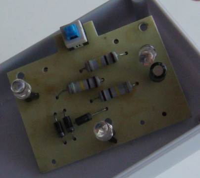
CLAP SWITCH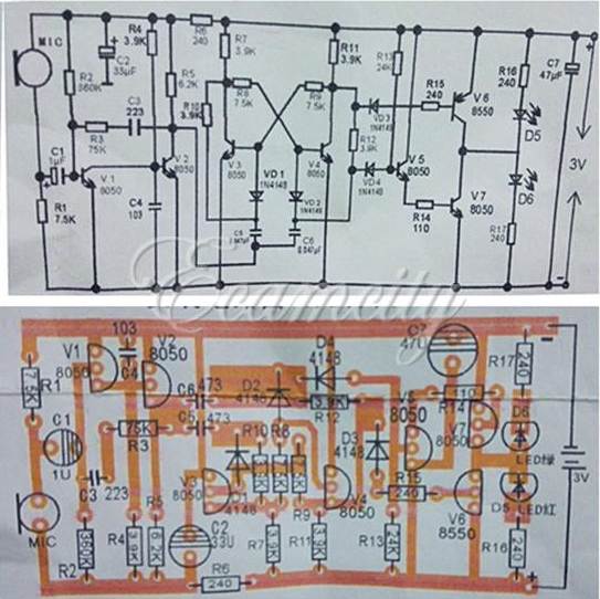
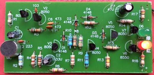
The circuit is a common design and it works very well. But the
components are placed on the board UP-SIDE-DOWN !!!!!
The positive rail is at the bottom of the board and no resistor values
are identified.
I have learnt NOTHING from this kit. How do you expect a beginner
to learn anything ???
The kits costs $8.00 in India.
The kit has been stolen from a Chinese manufacturer: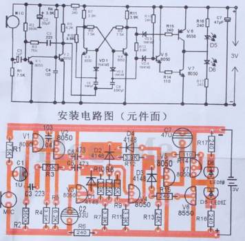
![]()
A reader of a forum requested a circuit to take 4 outputs of a receiver
and connect them to 2 inputs of his microcontroller.
Here's what an electronics engineer came up with:
Here is my circuit from a project:
4 Channel Remote Control.
It is much simpler than the circuit above and can be expanded to 6
inputs.
To start with, the 100n across the input does not create a "floating
input."
Picbuster replied with more incorrect
statements:
"How to discharge cap after loading it via the diode? ( it remains high
until discharged by mpu's input impedance."
An input is considered to be floating when it can pick up stray voltages
and rise and fall very quickly and the micro detects values that it
cannot deal with. When a 100n is connected to the input, it charges and
discharges very slowly and does not charge via stray voltages or
interference from electromagnetic waves.
The 100n capacitor is discharged by making the pin an OUTPUT and taking
it LOW to quickly discharge the 100n.
![]()
TIMER
The IRF530n is actually a POWER MOSFET and needs 2v to 4v to turn on so
it is not really suitable for this circuit. The
main point at the moment is to draw a circuit so you can how it works.
Once you see how it works, you can see the gate voltage of the SCR (or
MOSFET) must be less than 2.5v for the device you are selecting as this
is the maximum voltage available.
![]()
Pin 2 is floating and this pin has a high impedance. The voltage on the
pin is unknown.
Wasim Khan from
http://www.electricaltechnology.org emailed me to say he didn't have
a clue what I was talking about, so here is the corrected circuit:
Pin 2 in the original circuit is floating and although the 555 may work,
pin 2 must be held above 33% of rail voltage so it does not activate the
chip until required.
The 2u2 has no polarity. The timing capacitor has no value. The 100k pot
does not have the wiper connected. The green LED does not have a dropper
resistor. The sequence
for the 4017 is 3 2 4 7 10 1 5
6 9 11. Pin 12 is HIGH during the time
when 3 2 4 7 are HIGH. The LED sequence is correct.
![]()
I think it is fantastic that badly designed circuits made by others
and put on the internet, are shown for their errors.
It is a great teaching source for those who want to learn about the in�s
& outs of electronics, in such a practical & clear way.
Yes, it can also prevent one from building a circuit, only to find out
that it does not work.
Keep up the great work and website.
Regards
Craig Adkins
PC Hardware & Software Support![]()
TOGGLE
The LED is turned off by SHORTING ACROSS THE POWER SUPPLY !!!!![]()
Here's another faulty design from
The original circuit is shown in B and it looks to be ok until you see the 100k
resistor inside the TSOP 1738 and the 10k on the main circuit.
These two resistors form a voltage divider and when the transistor is not
activated, the maximum voltage will only rise to 10% of rail voltage. The
voltage will go from 0% to 10%
This will not allow the chip to clock. The circuit WILL NOT WORK.
![]()
LEAKAGE
Here's a problem with LEAKAGE.
This is when a very small current flows through a transistor (or any other
component) and this current cannot be reduced or stopped.
See more on LEAKAGE in
The
Transistor Amplifier P2 article.
In the following example, Q1 is a leaky transistor. It can be any type of
transistor and although the leakage current flows via the collector-base
junction, we can assume the transistor is exactly the same as a 470k
resistor.
If we place a resistor from the supply to point A on the diagram, we will create a voltage divider and 6.4v will be at point A.
The base of Q2 will see a voltage of 6.4v but no current will flow in the base and thus the LED will not be illuminated.
The leakage comes via the 190k resistor and the LED is not turned on.
The base resistor for the first transistor will have to be reduced to 2k2 so the
transistor will turn OFF when the input voltage is zero. Silicon
transistors are very leaky and should NOT be used in this type of circuit.
![]()
IR LED
Here's a dangerous circuit:
The voltage drop across each Infrared LED is about 1.5v to 1.9v.
This produces a maximum of 6v.
When the transistor is turned ON, the voltage across the 5R6 can be up to 6v.
The current through the 5R6 can be as high as 6/5.6 = 1amp !! Most IR LEDs
are designed for 30mA to 100mA. They will be damaged in this
circuit.
By adding 1 more component, the output driver transistor can be converted into
a CONSTANT CURRENT device and the current set by the value of R to suit the IR
LEDs and deliver the same current for a supply voltage from less than 9v to 12v
or slightly more.
![]()
CHARGER
Here's a circuit that will not work:
The transformer will produce 4.5v x 1.414 = 6.3v minus 0.7v drop across
the diode = 5.6v
The current through the 39R will be 5.6v - 4.5v = 1.1v / 39 = 28mA.
The IDIOT "Professor D Mohankumar" said the maximum current
through the 39R will be 115mA due to 4.5v / 39 = 115mA. BUT the
current is due to the VOLTAGE DROP ACROSS THE RESISTOR - the voltage
that will be across the resistor when the battery is included in the
circuit and this voltage will be 1.1v NOT 4.5v !!!!!!
How can you become a "Professor" of electronics in INDIA
when you don't understand the simplest electrical circuit ????
What about his students ??? How are they going to learn
electronics ???????
Here's another DANGEROUS circuit from "Professor D Mohankumar:"
You cannot use an ordinary transformer to charge a battery.
A battery-charger transformer is specially designed to produce the EXACT
output voltage for a 6v, 12v or 24v battery.
A fully charged 12v battery has a terminal voltage of 13.6v and the peak
voltage from the winding must not be greater than 13.6v plus the voltage
drop across the diode plus the small voltage drop across the ammeter and
the leads.
When the battery reaches 13.6v, we want a small "trickle charge" to
enter the battery of about 50mA to 300mA, depending on the size of the
battery.
We also want the battery-charger transformer to deliver say 5 amps when
the battery is less than 13.6v and we specially want the current to be 5
amps when the battery is 12.6v
In other words we need the current to rise enormously, when the voltage
is below 13.6v and taper off to almost nothing when above 13.6v.
This can only be done with a low-impedance transformer (low-impedance
winding) and explaining this is very technical and will not be covered
at the moment.
A normal 14v - 0v -14v transformer will produce a peak of 14v x 1.4 =
19.6v and will deliver about 19v to the battery.
This voltage is TOO HIGH and two things will happen.
Firstly, the current will be greater than 5amps and the transformer will
BURN OUT.
If it does not burn out, the current will continue after the battery is
fully charged and the water in the cells will "boil off" and the battery
will "dry out."
A battery is not like a normal resistive load. When it reaches 13.6v, it
is just like a ZENER DIODE.
We know how a zener diode works. When its specified voltage is reached,
the voltage across it does not rise any further and all the current
flows through the diode.
This is exactly what happens with the battery.
We have a transformer producing 19v and a zener allowing 13.6v to appear
across it. We have a CLASH OF VOLTAGES. During each cycle, no current
flows until the waveform reaches about 14.5v and then the output voltage
see a SHORT CIRCUIT. A normal short-circuit starts at 0v output and will
burn out the transformer. This time it starts a 14.5v and continues
until the output voltage reaches a peak (in our case, about 19.6v). This part of
the waveform will deliver an enormous current and will be enough to
over-heat the transformer.
![]()
A poster on an electronics forum asked about his circuit.
The circuit is well-deigned and very simple:
A "electronics engineer" came up with an "improvement:"
The "improvement" is more complex, uses a larger switch and 2 extra
diodes.
This is just one more example of the incompetence of "electronics
persons" in designing a simple circuit.
You will find this flows through all the electronics forums.
So many of the "electronics wizards" have little or no understanding of
the basics of electronics. They may be able to master a CAD
package, use circuit analysis software but when it comes to
intelligent-designing, they "fall off the boat."
All you have to do is change the connections and the first circuit can
be used !!! You don't need a DPDT switch and two diodes !!!!
That's why a Masters in Electronics from a University doesn't always
help.
Most Boost Converters have the input isolated from the output via a
high-frequency transformer, and this must be the case for this circuit
to work as the negative output of the converter will be be below 0v.
(taking the negative of the battery as a reference 0v).
![]()
POOF!!!
There are hundreds of new and exciting chips and products being
developed and reviewed on the web, but you have to be very careful about
including anything in your designs.
Many of these new devices are not stocked by any supplier and sometimes
you have to buy a whole roll (3,000 pieces) to get your order fulfilled.
Take the PR4401 inverter chip to drive a white LED from 1.5v.
It is worth 5 cents but costs 70 cents and the supplier shows a stock of
994 pieces aster 3 years !!! He has sold 6 pieces !!
Most of these recently developed chips are too expensive and and will be
deleted from inventory after a few years.
When designing a product, you have to think of a life-span of 20 years.
Many of the items I produce are 25 years old and they can still be
produced because I have used readily-available components.
All the kits using special parts have been deleted as the chips are no
longer produced.
If you are not careful, this can cripple your business.
A new product or chip may look tempting but others will see the item too
and if sales are less than expected, you will see the product on eBay
for $1.00. Just look at the Arduino modules. A $10.00 product is
now $2.00!!
Lots of these new chips will disappear . . . . POOF!!!
![]()
Here's another
poorly-designed circuit from "Professor Mohan Kumar:"
The
second transistor is not needed. If the first transistor is capable of
delivering 30mA for the buzzer, it will also be able to illuminate the
LED:
All these points, discussions, criticisms are referred to as
"second-order understanding."
There is a constant stream of new produces and chips on the web but you
have to be careful.
The circuit will NOT work. A 3v solar cell through a diode will no
charge a 3v battery. The "floating voltage" produced by 3v battery when
it is being charged is nearly 4v and you need a voltage higher than this
to charge it.
Mohan Kumar says:
NIGHT
This time we are talking about a 240v LIVE circuit. The 225 will pass up
to 150mA and this will cause over 325v to be developed across the 47k
resistor. The 47u 25v electro will BLOW UP!!!
BOAT LIGHT
When ever you have a potentiometer in a circuit, make sure it does not
damage any of the components if it is turned fully clockwise.
He doesn't test anything. He does not understand electronics AT ALL and
yet he still keeps adding his faulty circuits to the web.
There is no current-limiting resistor between the 12v supply and 9v
rechargeable battery. The battery will BLOW UP !!!
Here's a 555 circuit from an "electronics engineer" in a forum:
The output is required to deliver 1 amp.
EARTH
Mohan Kumar says:
Here's
what's inside:
The item has NO ultrasonic components. The LEDs simply
illuminate !!!!
R2 ????
Second-order understanding is when you take a circuit and see if it can
be simplified or improved so someone with greater understanding cannot
criticise it.
You will never find this concept in any text book.
It's wonderful to churn out mathematical formulae but an equation will
not design a circuit for you.
It's like a person buying a CRO to design a circuit by seeing the
waveforms.
You have to know which components to change to get greater amplitude or
higher frequency or shorter mark-space ratio. You have to know
what the waveform will look like before viewing it, otherwise you will
be "tricked" by what you see.
The same with mathematical results.
You must write down what the result should be and see if the equation
conforms your understanding.
The same applies to the circuit above.
If the first transistor can deliver 30mA to the buzzer, why not include
the LED ???
It's simple "electronic understanding." ![]()
Most of these are very exotic and perform wonderful tasks, but they are
very expensive and very few suppliers stock them. On top of this, there
is no guarantee that the item will still be available in 3 years time.
The other big problem is copyright. if you design something that takes
off and has a long=term future, you will find others will copy the idea
and use cheaper components.
No only will they under-cut you but your copyright and/or patent will be
worthless.
Chasing up an infringement will cost $50,000 and the chance of finding
the manufacturer will be zero. Look at all the clones that come onto the
market after a few weeks.
People work 25 hours a day to copy things and they generally have a much
bigger distribution market. They will out-strip you 10-fold
Here are t he two points to note:
Don't waste your effort, money and stock in exotic components.
Don't waste time in paying for a patent or registered design. You are
only alerting the copiers to your idea and giving them 4 weeks
"head-start."
![]()
 Here's
more rubbish from "professor" Mohan Kumar:
Here's
more rubbish from "professor" Mohan Kumar:
Secondly, a white LED has a characteristic voltage across it of between
3.2v and 3.6v.
The 3v battery will be less than 3v via the transistor and the LED will
NEVER illuminate. Just another untried, untested, junk circuit from an
Indian Professor.
What is the purpose of the 100u electrolytic??? It does
nothing.
He has been informed of his mistakes for over 18 months and he still
keeps adding more junk to the web each week. When will he learn??
NEVER !!!!!
CHARGE CONTROLLER
Here's
more rubbish from "professor" Mohan Kumar:
The charging current will be:
12V / 127 = 0.094 Amps or 94 mA.
This is NOT TRUE.
The charging current will be: THE VOLTAGE ACROSS THE TWO RESISTORS
DIVIDED BY 127 OHMS.
The voltage across the resistors will be 12v minus the voltage produced
by the 9v battery when it is being charged. This will develop a
"Charging Voltage" of at least 10 volts.
This means the voltage across the 127 ohms will be 2v AND NOT 12v.
The maximum charging current will be: 2 / 127 = 15mA.
The maximum voltage across the 27 ohm resistor will be 0.4v and the
transistor will never turn on.
Another untried, untested circuit for this Indian Professor."
![]()
Here's
another disaster from "professor" Mohan Kumar:
The current required by the circuit is only about 10mA to illuminate the
LED so the 225 capacitor should be 220n (224).
The 47k R3 should be 100R.
To turn OFF the circuit, the resistance of the LDR must be reduced to
1,000 ohms because the base voltage of T1 must be 0.5v to turn the
transistor OFF. This is created by the voltage divider of the LDR
and 22k pot.
The 1k8 resistor will simply slow down the change from OFF to ON and ON
to OFF. It's not a good place to put a resistor. ![]()
In the circuit above, the LDR will see full rail voltage when the pot is
turned and if the LDR is in bright sunlight, its resistance will be very
low. It may get damaged.
![]()
EMERGENCY LIGHT
Here's
another disaster from "professor" Mohan Kumar:
This circuit does not work.
The gain for the BD140 is up to 250, but this is in a test circuit and
pulsed at a duty cycle of 2%. This is totally unrealistic and when the
transistor is placed in a real circuit, the gain is less than 100.
When the transistor is turned on via the 2k7, the base current will be
3.4/2700 = 1.2mA. This means the maximum collector current will be
120mA.
The characteristic voltage drop across a white LED is a minimum of 3.2v
and this allows 4v - 0.2v across the emitter-collector junction - 3.2v
across the LED = 0.6v across the 47R resistor.
The current through the 47R will be 12mA.
Why use 500milliwatt LEDs ???
Most white LEDs have a characteristic drop of 3.4v to 3.6v and this
circuit will not work AT ALL.
![]()
PHONE CHARGER
Here's
another disaster from "professor" Mohan Kumar:
There is no switch between the 9v battery and regulator. The regulator
takes 10mA all the time and will flatten the battery.
The output of the regulator is 5v minus 0.7v = 4.3v. It is NOT 5v.
The mobile battery will see 4.3v minus the voltage across the red LED
(1.7v) = 2.6v. The mobile battery will NEVER get charged.
I don't know how Mohan Kumar became a "Professor." It
just gives teachers a bad name. None of his circuits work and none have
been tested. He says I don't know what I am talking about.
Let the 22 million readers of Talking Electronics website be the judge.
![]()
Two faults with the circuit.
The output of the 555 does not rise to 11.4v to turn OFF the PNP
transistor. It rises to about 10.3v.
When the output is HIGH the voltage across the 1k base resistor for the
NPN transistor will be almost zero, even though the emitter is minus 2v
compared with the 0v of the 555. The NPN transistor will never turn ON
!!!
That's why you have to build a circuit and not rely on a simulation
package.
![]()
WHY DIODES AND BRIDGES
FAIL
Diodes and bridges fail when the current
increases.
The main problem is this:
A diode rated at 1 amp is really a 700mA diode. The voltage-drop across
a 1 amp diode at 700mA is 750mV. This gives a wattage dissipation of
about 0.5 watts.
When the current increases to 1 amp, the voltage across the junction
rises to 1.1v to 1.2v. This fact is never mentioned anywhere and that's
why you have to test a circuit and see what is really happening.
At 1 amp, the diode is dissipating more than 1 watt and if the printed
circuit board does not have large solder-lands, the diode will
eventually fail.
The same reasoning applies to bridges.
When a bridge is connected to the output of a transformer, the waveform
is sinusoidal (AC) and as it rises to a peak, that's when a very high
current flows, because as the voltage falls, very little current flows.
To get an average of say 1 amp, the peaks must be a lot more than 1 amp.
During the peak, the current might be 3 amp and the voltage across the
diode 1.2v. This is 3.6 watts for a short period of time.
Now you can see why a diode can fail.
![]()
Here's
another disaster from "professor" Mohan Kumar:
When the wiring is proper, a potential difference develops between the
Neutral and Earth lines and T1 turns on to light the LED.
This is INCORRECT.
Plugging this circuit into the wall socket will NOT illuminate the LED
because the Earth and Neutral will be at the same potential.
At NO TIME will the earth be at a higher potential then the Neutral.
I am amazed that Mohan Kumar is still alive, with his mis-understanding
of the mains.
How can he teach this RUBBISH to his students ???![]()
Here's fraud from
![]()
I am having enormous trouble getting a refund. That's because
Alibaba does not have paypal. They debit your credit card. Another
FRAUD from Alibaba.
![]()
Here's
another circuit from "professor" Mohan Kumar:
What is the purpose of R2 ???? It does nothing.
That's why you need electronics experience before putting this type of rubbish
on the web.
The following comes from T.K. Hareendran.
Note that switching threshold is determined by a 470k potentiometer
(VR1) that causes the output to toggle with the preset threshold values.
The light source (LED2) automatically switches on when it gets dark and
switches off when there is sufficient ambient light.
POWER SUPPLY
Mohan Kumar does not know how to calculate the voltage across the
various components. 
![]()
The 100�F capacitor (C1) provides a bit of hysteresis to prevent the
circuit from jittering near the threshold level.
The 100u has no effect on the hysteresis or the threshold values. These
are determined by the 555 and the 12v supply.
The 100u simply prevents the voltage on the top of the LDR rising or
falling rapidly.
The 470k pot forms a voltage divider with the LDR and it changes the
level of light needed to make the chip change states. ![]()
Here's another disaster from "professor" Mohan Kumar. And it will BLOW
UP !!!!!!
He does not know the basics of the power supply.
The whole design revolves around the current delivered by the two 1u
capacitors. This is 150mA.
The circuit is a CONSTANT CURRENT design and the 150mA will pass through
the 470R resistor, the zener and the 10R resistor.
The voltage across the 470R resistor will be .15 x 470 = 70 volts.
The 25v electrolytic will BOW UP. You can see it has already blown up in
Mohan Kumar's photo.
The wattage dissipated by the 470R will be V x
The dissipation of the zener diode is V x
I = 12 x .15 =
1.8 watts. The zener in the photo is only 400mW.
Mohan Kumar has done no computations and just because he has tried it
for a few minutes, does not make the circuit acceptable. It
is an absolute disaster.
This power supply WILL KILL YOU. If it doesn't electrocute you, it will
burn the house down.
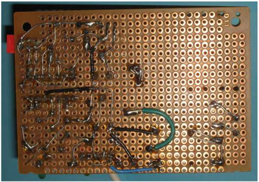
The kit is built on MATRIX BOARD !!!!! The
author hasn't even bothered to make a PCB for the kit.
The complexity of this project necessitates a PCB, especially as the
mains is connected to the board.
Page 1
Page 2
Page 3
Page 4
Page 5
Page 6
Page 7
Page 8
Page 9![]()
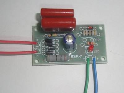
SENSOR KIT
This is one of the reasons why kits have such a bad name:
And the kit sells for $45.00 !!!
And the instructions say to use the circuit diagram as the diagram above
is not correct !!!
RELAY, SPDT, 12VDC, 360Ohm, 15A,120VAC
Relay can turn on/off AC appliances (300W max)
Why specify 15 amp relay for 2 amp load ?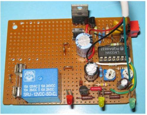
Look at the poor layout and the power lead ALL OVER THE BOARD !!
![]()
![]()
Page 10
Page 11
Page 12
Page 13
Page 14
Page 15
Page 16
Page 17
Page 18
Page 19
Page 20
Page 21
Page 22
Page 23
Page 24
Page 25
Page 26
Page 28
Page 29
Page 30