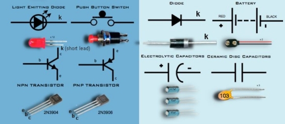
SPOT
Page 1
Page 2
Page 3
Page 4
Page 5
Page 6
Page 7
Page 8
Page 9
The internet has changed. Originally we had all sorts of scammers
wanting you to sign up to download data sheets for $30.00 per month and
electronics websites for $39.00 per month.
JOB FUTURE - JOB SECURITY
THE MISTAKES!
Page 30
Page 10
Page 11
Page 12
Page 13
Page 14
Page 15
Page 16
Page 17
Page 18
Page 19
Page 20
Page 21
Page 22
Page 23
Page 24
Page 25
Page 26
Page 27
Page 28
Page 29
Page 31
![]()
The only way to learn electronics is to build little projects such as
"games" or flashing lights, radios or transmitters.
That's what I did when I was learning and I reproduced the fun in my
magazine TALKING ELECTRONICS, for 20 years.
I helped thousands of beginners into the world of electronics and many
of them are still in the field and sending me emails.
If you look at the the current range of electronics magazines, not one
includes simple projects for the beginner.
How to they expect to increase their readership if they don't respond to
the needs of those who are just beginning?
Obviously they aren't.
The readership of these magazines is declining rapidly and all of them
are at the end of their life.
Their claimed "readership" is just a myth and if you were to get hold of
the "print run" you would be horrified.
They live on the smell "of an oily rag" and some have have disbanded
their projects-staff and rely on contributions from readers with little
understanding of electronics. Many of the circuits don't work or are
poorly designed and the prototypes are build on "breadboard!"
Even adding one beginners project a month is an insult. The magazine
should be filled with projects and ideas.
Many of the pages are their own advertisements and one
magazine has 10 irrelevant pages and not one beginners project.
There are simply speeding up their demise and many have already gone.
![]()
And we had all those pyramid schemes, offering up to $1,200 to get new
investors to join the scheme.
Fortunately, all these sharks have gone and now the internet is
basically free to enjoy.
The change started with a few people offering free information and as
Google improved their "spidering" skills, the content of these sites
became available in the search engine.
My first website took 9 months for the "electronics hub" to list it on
their website and now new content can appear the same day.
Fortunately the power has been taken away from those nasty, selfish "hub
owners" and no-one can hold you for ransom and ask you to join a hub to
get exposure.
The only fraud left is all those GIFT CARDS.
It is just a way to collect your information. There is no CARD at the
end of the survey.
I get hundreds of scam emails each day and you cannot filer anything as
you will remove legitimate orders and requests for information.
Hundreds of "companies" want to change or improve my website.
I get 10,500 visitors a day (22 million to date) and not one has said the
website is poor or needs improving or updating.
I hate those websites that push the advertisements throughout the page and you have read between the ads.
It's no wonder they get very little readership. ![]()
These are two different problems facing anyone in the workforce.
Here's a way to explain it: A particular line-of-work may be expanding
and looking to have a bright future. But there will be many interested
parties looking at the same "growing sector" and maybe Universities will
provide courses and qualifications. All of a sudden the market gets
flooded with new applicants and work gets reduced or "dries up" due to a
"bidding war."
Or maybe technology changes or improves or becomes "cornered" by
overseas companies.
This is a changing world and you can realistically say technology
doubles each year and prices halve.
But certainly don't think the products you are working on at the moment will be around in 5 or 10 years. Things will be totally different.
That's why you have to get 2 or 3 strings in your "bow" and consider
various and different applications and jobs, so you don't get
frustrated when things slow down.
The greatest change to our life is and will be the ELECTRIC VEHICLE.
The impact will come in 3 directions.
1. Manufacture
2. Buying and running
3. Charging.
The electrical distribution system is not set-up for the burden that
will be placed on it if the sales of these vehicles "takes off."
Most distribution networks allow 30 amps per household. But the whole
network can only support 25% of premises with this demand. That's why a
BLACK-OUT occurs on a hot day when households turn on their air
conditioners and ask for 10 amps or more.
Suppose we take the smallest battery for an electric vehicle as 60kWHr.
Suppose we want to deliver 40kWhr to the battery over a period of 10
hours.
This would require about 20 amps.
This is the longest, slowest charge you can provide and it already "eats
into" the 30 amp allowance.
The whole distribution network will have to be upgraded if electric
vehicles become popular.
![]()
JUNK MARKET
Gone are the days when you could go to a junk electronics shop and only
find junk and rubbish.
These shops now have parts, components and modules that can be new,
surplus or removed from products.
And they can range from perfect, to a good source of components.
If you are beginning, learning or wanting to increase your parts supply,
they form a very good source of components as well as modules than can
be incorporated into other designs or simply pulled apart for
components.
But the important to is to go to these shops regularly and keep up your
interest in electronics, even if it is pulling things apart.
Too many students come out of University, have made not a single project
on their own and having nothing at home but bare floorboards.
Understanding electronics does not come from reading more and more text
books.
A book does not improve your soldering skills. Nor your multimeter
skills or your fault finding ability.
These only come from handling, soldering de-soldering and trying and
testing and experimenting and fault-finding and eventually perfecting a
project.
And the cheapest way to do this is to go to the junk shops or even pick
up things in the street and pull them apart.
You will find the highest quality motors, servo's, amplifiers, speakers
and lasers and you can learn more from playing with them than any text
book will offer.
I could talk about the design of a quality, powerful motor for 100 hours
without stopping. That's how much there is to know about its features.
Just imagine how long the discussion would last for some of the other
modules.
So don't think Junk Shops are full of worthless junk. They are the basis
to your future education.
![]()
STONE SOUP
You may have heard the story: STONE SOUP.
It is a story about fooling people nearly all the time by merely telling them something or repeatedly telling them the same thing until they believe it.
Here's how the story goes:
A hobo (a wandering tramp) goes to a farmer�s house with a large shiny river pebble and asks the lady of the house if she could provide a pot of hot water to make some stone soup for lunch. The polished river stone is dropped into the pot of boiling water and stirred to put some scrumptious taste into it. After tasting the delicious concoction, the hobo asks the lady for a few potatoes to give it more body. Next it needs some carrots and then some onions.
The lady and the hobo have their fill of stone soup for lunch. The hobo removes the stone and leaves.
The lady can't wait to tell her husband how a delicious lunch was made with practically nothing but a river pebble.
![]()
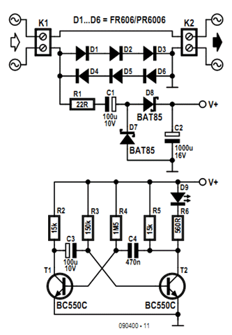
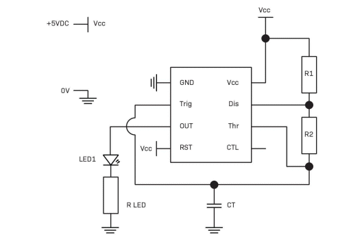
LED TORCH CIRCUITS
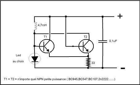
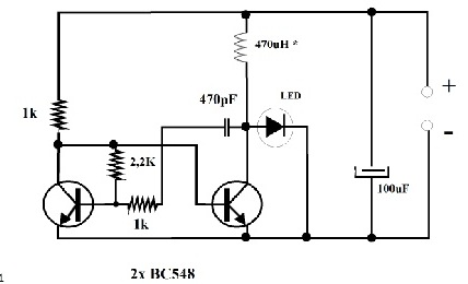
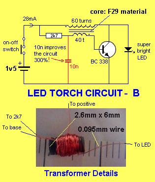
We are going to talk about GOOD DESIGN and how to "see" and
"work-out" a good design. The top tow circuits are not
necessarily MISTAKES, but the fall into the category of BAD DESIGN.
The third circuit has been designed by ME.
It is a good design, because I know how to create good designs.
The other two are BAD DESIGNS.
My circuit has a feature called REGENERATIVE ACTION.
This is a FEEDBACK SIGNAL that turns the circuit ON more and more.
In other words it is a POSITIVE FEEDBACK signal.
The driver transistor (actually the OUTPUT TRANSISTOR) needs energy into
the base to turn it ON. This is WASTED energy because it does not
deliver any energy to the LED. So we want to keep this as low as
possible.
In the third circuit, the supply delivers some of the base energy via
the 2k7, but this is just enough to start the circuit operating. Once
the circuit starts to turn ON, the feedback winding gets energy via the
magnetic circuit of the inductor, from the main winding, and this turns the
transistor ON more and more. When the transistor fully turns ON, the
magnetic flux stops expanding and nothing is delivered to the feedback
winding. This creates the next part of the cycle.
But the point I want to emphasize is the fact that the base is only
getting energy when it is required.
In the first circuit, the first transistor is turning off the second
transistor by creating a large current through the 33R. This
is like turning off your washing machine by loading the supply with 100
radiators so the voltage of the supply drops to 10v.
Now you can see the wastefulness of the circuit.
The second circuit has a similar wasteful design.
The first transistor removes the voltage to the base of the second
transistor by taking the 1k to within 0.3v of the 0v rail.
And during this time we are wasting current through the 1k resistor.
Neither circuit has a regenerative action to turn the output
transistor ON.
This understanding might not be important in a hobby circuit, but in a
commercial design, you need to know what you are doing.
![]()
INDUCTION MOTOR
I had to comment on the operation of the induction motor because so many descriptions brought in complexities such as "salient" poles and "Lenz Law" that I could not understand what they were trying to convey.
Here is a simple diagram of a SHADED POLE MOTOR commonly called an INDUCTION MOTOR. They are used in fans and other small appliances up to about 100 watts. They have a constant speed of rotation of 3000RPM for 50 cycles (Hertz) supply.
The diagram is not very good as it does not get into the finer points of
how the "magnetism" rotates.
The Induction (shaded pole) motor actually has 4 poles because a 2-pole
motor will rotate in either direction. The induction motor rotates only
clockwise.
We will just deal with the top pole. The shaded pole is smaller, mainly
because it has been found that the pole can be smaller.
As the voltage rises, the flux enters the whole pole at the same rate
and it passes to the armature where it flows into a copper rod or bar.
We will cover this in a moment.
At the same time the flux passes through the small pole that has a thick
copper ring or strap or wire around it.
We now have to describe something.
The thin pole is actually a transformer.
If you take a transformer such as a battery charger transformer and
short the output, the secondary will get very hot. This is because all
the energy from the primary is being passed to the secondary via the
magnetic flux.
That is exactly what is happening with the induction motor.
The flux passing down the small pole is creating a current in the copper
wire and thus almost no flux is appearing at the end.
Thus all the flux is appearing at the end of the main part of the pole.
This flux enters the armature and it has cuts around the circumference
so that the flux passes into the armature. The armature is very similar
to the shaded pole of the "field" in which a thick copper rod has been
placed through the middle of the pole and welded to the top and bottom
plates of the armature. The other rods create the return path to create
a full turn.
This is only the first half of the story.
These copper rods are called a SHORTED TURN and a very high current will
be produced in them. A very high current in a single turn is equivalent
to a lower current in a coil of many turns.
You can see the field coil (connected to the mains) has many turns and
only a small current flows. The shorted turn has a very high current
induced in it and is equivalent to a portion of the field coil with
respect to the amount of flux it will produce.
The armature is made of soft iron laminations and is not magnetic. In
other words it will not pick up nails.
But it will be attracted to a magnet and it will pick up nails due to
the current flowing in the rods.
All we are going to explain is the concept of how the magnetic field
passes across the pole to create a term called a ROTATING FIELD. There
is also a reaction (interaction) between the rotating field and the
field produced by the copper rods in the armature that drags (or draws)
the armature around to produce rotation.
As the current increases in the field winding, the magnetic flux in the
main pole increases. This flux creates a current in the shaded coil but
the flux does not come out the end.
Magnetic flux can only be converted to current in the shorted turn when
it is increasing or decreasing.
As the voltage rises to a maximum, the flux is not increasing at the
same rate and although the flux rises to a maximum, it is not absorbed
by the copper turn.
Thus we get the condition where the flux appears at the end of both
parts of the poles.
This has created a shift of flux density from the large part of the pole
to the whole of the pole.
Now the voltage starts to decrease and although it is still say a North
pole of flux, it is getting weaker.
The current flowing in the copper turn was always producing magnetic
flux but the flux produced by the field winding was always greater and
that is why the current was built up and maintained in the turn.
Now the flux is less than that produced by the shorted turn and it
produces flux in opposition to the decreasing flux and the effect is to
maintain the level of flux.
We now have the main part of the pole reducing in flux and the shaded
part maintaining the level of flux.
This produces the third part of the level of flux across the pole.
The armature picks up this flux because the laminations are slotted and
the rod is a shorted turn.
The slots are on an angle so the armature produces an even rotation and
it is pulled around by the movement of the flux across the pole. The
armature has many pole faces that produce "magnetism" just like the
shaded pole. Each rod has 2 pole faces but it is the rotation of the
field around the armature that determines the RPM.
![]()
MohanKumar knows practically NOTHING about electronics and yet he
persists in putting rubbish on the web that will bamboozle and mislead
the beginner.
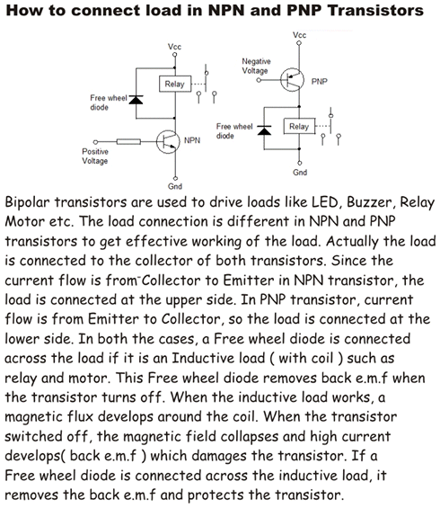
"When the transistor switches off, the magnetic field collapses and a
high current develops . . . ."
should be: "When the transistor switches off, the magnetic field
collapses and a high
The current is very LOW but the voltage can be very HIGH.
The diode should be called a DAMPER DIODE or SNUBBER DIODE or FLYBACK DIODE or SUPRESSOR DIODE or CATCH DIODE to let you know what it does. Calling it a Freewheeling Diode does not help the beginner.
The PNP transistor does not have a current limiting resistor in the base. The PNP circuit is very hard to implement as you need to have a controlling voltage very close to rail voltage.
MORE JUNK:
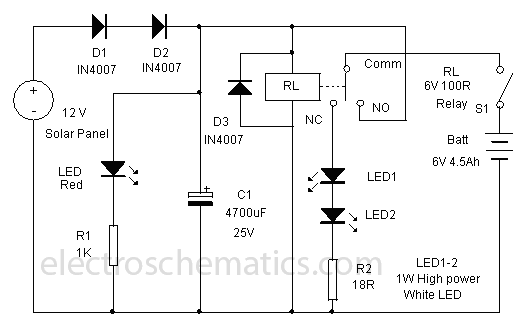
The relay is supposed to turn off when the sun does not shine on the
solar panel, but if you look at the circuit, the voltage from the
battery will enter the coil of the relay and keep it activated.
A relay only needs the slightest residual voltage to keep it active and
this is another circuit that has not been checked and tested.
You can do the same thing with a simple 10 cent transistor and not waste
50mA to 100mA on a relay.
High power 1 watt LEDs drop 3.2v across them and a 6v battery will not
illuminate 2 LEDs in series.
If the LEDs were to illuminate, they would take 250mA. 250mA
through 18 ohms would drop 4v !! The LEDs have to be in parallel.
I cannot see the point of two diodes D1 and D2.
And what is the purpose of D3 when there is no transistor driving the
relay !!! The contacts of the relay are also drawn incorrectly.
See how stupid the circuit is.
The whole circuit is just complete mess and a complete failure.
And D. Mohankumar is a PROFESSOR from India.
I think he has copied the circuit incorrectly. The second diode
should be after the relay.
![]()
PHOTO TRANSISTOR
![]()
This circuit
comes from an electronics forum where everyone is posting false and
misleading information and any beginner would be sent in the
complete-wrong direction. These are very dangerous platforms because
the respondents truly think their answers are correct.
It takes a lot of persuading to show where they are wrong.
The PHOTO TRANSISTOR is up-side-down.
All transistors are photo-transistors. All you have to do is expose
the junction and shine light on it. The problem is most transistors
are inside a plastic case and cannot be accessed.
And this means a photo-transistor has to be connected so the emitter
goes to 0v.
The reason why this circuit may work to a small extent is due to the
fact that t he transistor will work in either direction to a
differing extent and due to the gain of the second transistor, the
incorrect placement of the photo-transistor will not be realised.
Apart from this mistake, the values of R1 and R2 are incorrect, but
that is a discussion for another time.
![]()

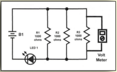
Here is some of the
RUBBISH from an "Educational" website:
Etron Circuit Labs
The inclusion of the 47R in the supply increases the impedance of the
supply considerably and the circuit may not work. The current
limiting resistor should be in the base of the PNP transistor.
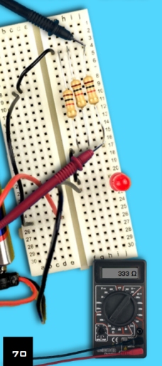
The circuit shows a voltmeter whereas the photo shows a multimeter.
This is not good enough for a "learning institute." Things
have to be described correctly.
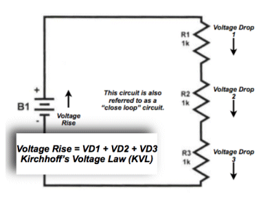
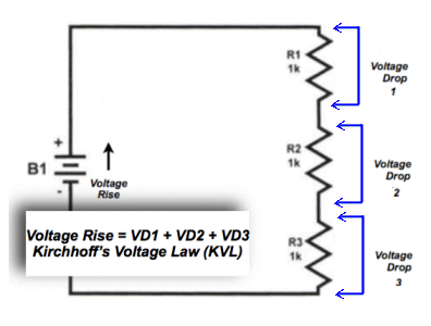
The voltage drop identification should be as shown by the blue arrows
to show that the VOLTAGE DROP that we are talking about, occurs
across each resistor.
Another terrible circuit. It is drawn up-side-down. A circuit is
actually a picture. It is designed to show how the components are
connected together and a qualified electronics engineer can look at
the circuit for one second and work out exactly how things are
connected. That is because there is an accepted way to position each
component and an accepted layout. If you draw things up-side-down
and around the wrong way and in the wrong places, this instant
recognition is LOST. It would take over a minute to work out if all
the components are connected correctly in the diagram above. This is
bad instruction for the beginner.
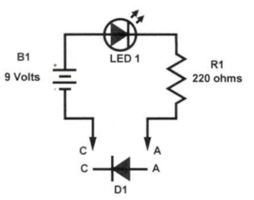
A diode is not labelled C and A. The only letter is
"k" on the cathode lead.
Another terrible circuit.
Note the improvements on the Parts List - as shown in the lower image.
It's just these little things that make it clearer for the beginner.
The website says a transistor can amplify voltage or current.
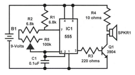
METRONOME
What is the point of the transistor buffer when the 555 is capable of
driving the speaker directly. 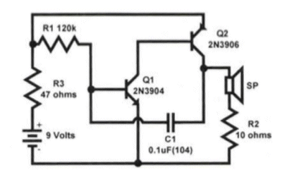
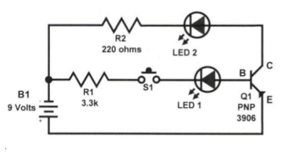
You don't place the "test component" in the negative lead. It is
placed in the positive lead.
The load resistor is always placed above the LED.
These are all the things an EDUCATED ELECTRONICS TEACHER should know
and obviously those in charge of ETRON website don't understand the
finer points to electronics educating.
Here is the correctly drawn diagram: 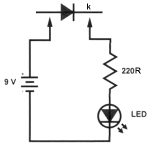
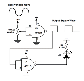
Why introduce another chip (4011B) when output pin 11 will drive a
LED.
The LED is badly drawn and does not teach the beginner the correct
way to draw a circuit. You don't draw things up-side-down with the
earth symbol "in the air."
In their digital section, they cover the LOGIC GATES: AND, OR,
NAND, NOR etc, but do not cover the EX-OR gate. This is one of
the most important gates because an OR gate is also an AND gate and
you may want to only produce an output when one of the inputs is
HIGH. 
It should say: A transistor can amplify voltage. It can amplify
current and it can amplify BOTH at the same time. It depends on the
how the transistor is connected and the surrounding components.
This is a very common mistake. There is no current limiting resistor
on the collector of the first transistor. When the first transistor
turns ON, during part of the cycle, it will be turned on very hard
by the action of the 100u electrolytic and current will flow through
the emitter-base junction of the PNP transistor.
This current will be very large and it may damage the PNP transistor
if the 9v supply is from a power supply. By including a 1k in the
collector, the current taken by the circuit will reduce
considerably. 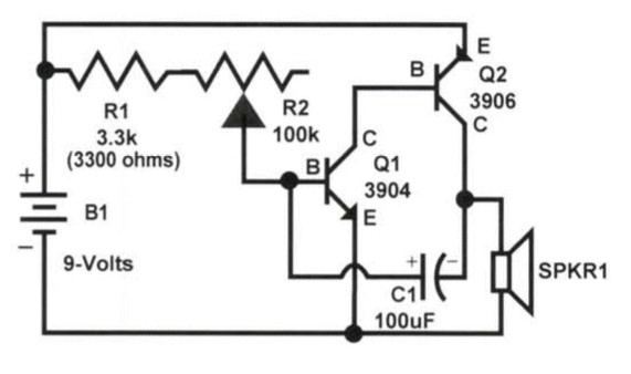
I have contacted ETRON via email and
![]()
Here is an obvious mistake from December
issue of DIYODE Magazine. The LEDs are up-side-down and
have no current limiting resistor.
You might think a resistor is not needed at 3.3v but a LED has a
characteristic voltage across it of 1.7v or 2.4v for red and green
and if the output does not have a resistor, it will be at 1.7v
whereas it would normally be about 3v. The output is actually a
microscopic FET and this incorrect voltage across it will increase the
heat generated by the FET by a factor of about 10 times. This might not be important for
a single driver-line but it shows a lack of understanding of
circuit-design and may reduce the life of the micro. If you had a
full port with the extra load like this, you may overload the whole chip.
This is a common mistake and is one of the identifying markers to
identify a professional electronics engineer.
When-ever you don't allow a FET to turn on fully, it will dissipate
a high wattage. The FETs in these micros are as small as a dot on
the screen of a laptop and can only dissipate 10mW. Load the outputs
incorrectly and you can feel the chip heat-up.
![]()
BASE VOLTAGE
Here is another mistake from December
issue of DIYODE Magazine.
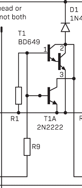
The resistor values do not matter. The
simple fact is the circuit will not work. The base-emitter junction
of the 2N2222 transistor will limit the voltage on the base to 0.7v.
The BD649 is a Darlington transistor and it needs 1.4v to turn as it
has two base-emitter voltages to deal with.
Fortunately the project does mention that the circuit has been
designed for EITHER transistor and it states that you cannot fit
both to the board. But this should be placed on the actual circuit
diagram so the constructor is aware of the fact.
![]()
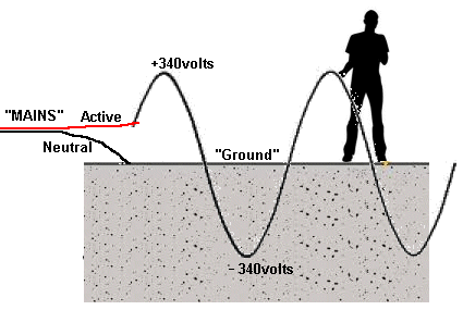
CAPACITOR POWER SUPPLY
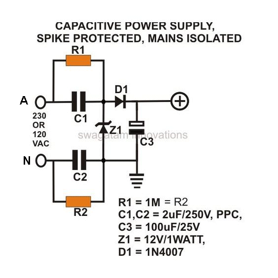
The two input terminals are generally
marked as "A" for Active and "N" for Neutral.
The following diagram shows the active line is rising 340 volts
above ground and then 340 volts below ground. The Neutral line does
not "move " at all.
Using this knowledge we can see the "A" line is connected to a 2u
capacitor.
The "N" line is also connected to a capacitor but the other side of
the capacitor is connected to earth so the "N" line is actually
directly connected to the project.
This means the "A" line will rise and when it reaches 12v, the zener
will start to conduct and the voltage will not rise any higher.
When the voltage falls, the diode will prevent the voltage on the
capacitor being lost to the charging circuit and when the "A" line
drops to about 1v below ground, the zener diode will act like an
ordinary diode and start to conduct. This action will discharge the
2u capacitor and allow it to start to charge it in the opposite direction. It
charges to -340v and when the waveform starts to rise, this voltage
is delivered to the zener because the capacitor can be considered to
be a 340v battery with the negative at -340v and the other end at
0v. When you push this battery "up," the end that is at 0v
will start to rise and when it reaches 12v, it cannot rise any
further. This is when the waveform starts to discharge the capacitor
and it will be fully discharged and then start to charge in the
opposite direction until it is charged to +340 volts.
Because the project is connected to earth, the lower 2u capacitor
does nothing and can be removed from the circuit with the 1M
resistor. The "N" lead can also be removed as it is now not
connected.
If the earth connection is removed the whole project becomes "live"
and you will get a shock. This means the project is NOT MAINS
ISOLATED.
![]()
Component layout like the arrangement above is very helpful for those
learning electronics but it does not take the place of a circuit
diagram.
A circuit diagram conveys WHAT THE CIRCUIT DOES and HOW IT WORKS via
the circuit symbols and the component values.
All this can be gained from the layout above but it takes 10 times
longer.
When you are dealing with lots of circuits, you need to work things
out quickly and only a circuit diagram will do this.
The web has encouraged this new wave of pictorial layouts and this
has brought a lot of new enthusiasts into the field.
I think this is a good thing but it needs a normal circuit diagram
to accompany all these pictorial diagrams.
![]()
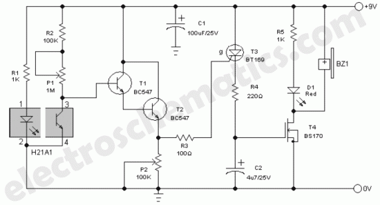
SMOKE ALARM
Here is a smoke alarm circuit and some comments from
Mihai Popescu
Some of his suggestions are correct, other are not correct:
Employ a resistor (say, 1kΩ or more) in series with emitter of T2 or P2. If P2 is at its minimum value (wiper is up�almost short circuit), then, the Darlington transistor(T1, T2) is subjected to all the supply voltage without a limiting current resistor. It will blow up for sure.
The thyristor T3(BT169) can�t be turned on because there is no resistive path to ground (cathode via R4 to GND)so there will be NO latch-up!
R3(100Ω) is way too small. It will drain the battery in no time. In fact it will draw more current than the buzzer(and the LED) itself. BT169 needs only 200�A on its gate to turn ON. A proper value for R3 would be 15KΩ�27KΩ.
The BC547 pair needs a current limiting resistor. But the 100k
pot must have a high resistance for the circuit to work, so it will
not be set at low-ohms.
The BT169 will turn ON when the gate is activated by the previous
stage as the 4u7 does produce a resistance in that it needs a
charging current and will be uncharged when the alarm is activated.
The 100R can certainly be increased to 27k, however the 100R will
not draw a high current because the 100k pot will be at least 50k
for the circuit to work.
![]()
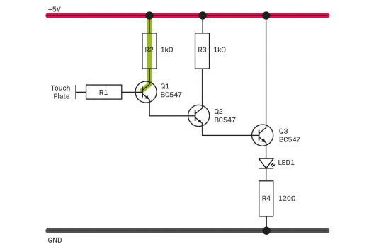
TOUCH SWITCH
It is a TOUCH SWITCH. A Touch Switch is supposed to turn ON and STAY ON when one of the pads is touched and turn OFF when the other pad is touched.
It has a FLIP FLOP arrangement within the circuit or a feedback arrangement called a LATCH that holds the circuit in the TURNED ON state.
There is no feature in the circuit that has been properly designed, to keep it ON when the finger is removed.
The circuit is relying on the fact that about half rail voltage and half the normal is current is flowing through the relay at all times. When the transistor pulls the relay in, the circuit is hoping the approx 50% current that is flowing all the time, will be sufficient to keep the relay closed.
This is a very bad policy because the contacts will be hardly touching each other, with any pressure, and any current through the contacts will burn the surfaces. The actual current through the coil will depend on the resistance of the coil and and if it is 100 ohms, the voltage will be 5v - 0.7v = 4.3v = 2.15v. It would be very doubtful if relay will remain energised at 2.15v. If the relay is 500 ohm, the voltage across it will be 3.6v and if it is 1k, the voltage will be 3.9v and it may remain activated all the time, and jump into activation when it is turned OFF.
This is simply NOT how to design a "LATCH."
It relies too heavily on selection of components, especially resistance of the relay and holding it feebly closed is only asking for trouble if a sizeable current is flowing.
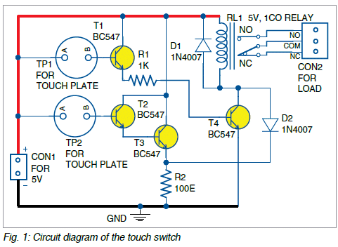
Here is the text from the magazine:
Working of the circuit is straightforward.
When TP1 is touched, the base voltages of transistors T1 and T4 go high.
As a result, relay RL1 energises to activate the load (light or fan)
through relay contacts. When TP2 is touched, the base voltage of
transistor T2 goes high and transistor T3 conducts. The
voltage developed across resistor R2 de-energises relay RL1 to
de-activate the load.
![]()
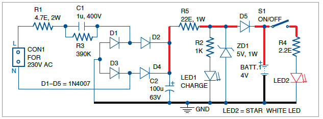
EGG CANDLER
Here is another junk circuit from Electronics For You
Magazine December 2017.
It does not matter what the circuit is intended to do. It is the
component values that don't make any sense.
They have just been taken out of a "parts box" without any thinking as
to their relevance.
What effect of surge protection will a 4.7 ohm resistor have???
Absolutely none. Maybe 100R to 20R will have some effect.
1u in bridge-mode will deliver 70mA.
The circuit is fixed at 5v via the 5v zener. The voltage-drop across the
22 ohm resistor will be 1.5v. The wattage will be 0.1watt. Why
specify 1 watt??
The voltage across the 100u will be 6v5. Why specify 63v ??
The voltage from the 5v zener, once it passes through D5 will be 4.3v.
A 4v battery will produce a floating-charge-voltage of more than 5.5v
when it is being charged and 4.3v will never charge it.
Another junk circuit that has never been tested.
![]()
6 DIODES
Here we have 3 diodes in series:
The diodes are 5 amp diodes and no mention has been made of the current
the project will measure.
But if the builder thinks the circuit will allow 5 amps to be detected,
the heat generated by each diode will be 5 watts, making a total of 15
watts for the 3 diodes. They will get so hot, the solder will melt and
they will fall off the board.
No heatsinking has been provided and the project is limited to a maximum
of 500watts.
![]()
5 AMP POWER SUPPLY
You have to be careful with anything you see on the internet, especially
high current power supplies.
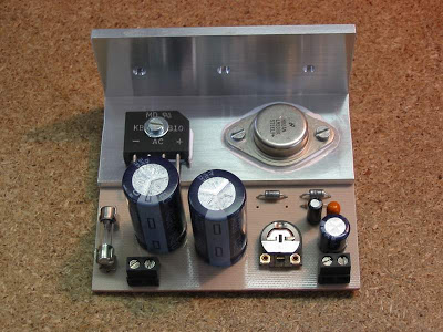
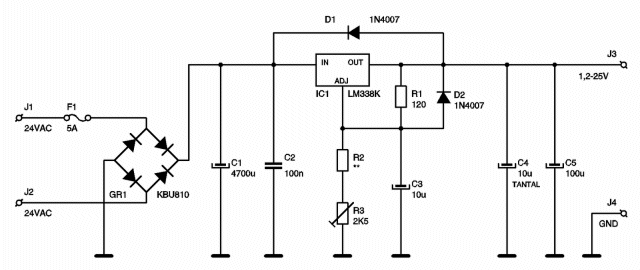
The circuit and picture look very interesting. But a lot of facts have
been overlooked.
The author suggests using a 24v AC transformer @ 5 amp.
When this transformer is connected to a bridge, the DC voltage becomes
24v x 1.4 = 33.6v.
The wattage of the transformer is 24 x 5 = 120 watts.
Since the DC voltage is 33.6v, the current must be de-rated to maintain
the 120 watt rating of the transformer.
This means you can only expect a current of 3.5 amps.
The wattage being dissipated by the regulator will be a maximum when the
voltage is the lowest. Suppose we set the output to 5v.
The voltage across the regulator will be about 30v - 5v = 25v.
If the current is 3.5 amps, the wattage being dissipated will be 25 x
3.5 = 87 watts.
The heatsink will not be large enough to dissipated 87 watts.
Where are you going to get a 2k5 pot from???
The project is supposed to be a bench power supply capable of producing
an output from 3v to 25v.
The PC board has a mini trim pot. Who is going to get fine
screwdriver and adjust the pot every time a new output voltage is
needed.
If the pot is 2k and you make R2 = 470R, the minimum output voltage will
be about 5v. Otherwise the max voltage will be 20v with a 2k mini trim
pot. If the 120R is reduced to 100R the output voltage will increase to
24v. If the 120R is reduced to 82R, the output voltage will increase to
29v.
![]()
The amount of mis-information on Electronics Forums is amazing.
Here is a comment from an "Audio Guru" who has made many faulty and silly comments about all sorts of things he knows nothing about.
The discussion was on a contact microphone, and he stated:
A piezo transducer picks up vibrations like from a guitar, piano or car engine. It makes a poor microphone.
I use a piezo on a window and the result is just like you have removed the sheet of glass. I have sold many "wall bugs" to those who want to listen to people in a room. The result is PERFECT.
Just because you don't think a stiff sheet of metal will not work as a microphone, do not make any comment until you have actually tried it.
Of course the result surprised us all, but that's the mystery of electronics. It surprises you every day.
CIRCUITS!!
Here are two circuits from DIYODE Magazine.
The article is trying to explain how to draw circuits.
The main problem with the component values is a technical issue.
You have to know what you are talking about when discussing these things
with a technical person such as Colin Mitchell.
The three stages consists of a low impedance stage driving the LED, then
a higher impedance stage in the middle and a very high impedance stage
at the front.
The gain of each transistor will be more than 100, (about 200), so if
the LED takes 25mA, the middle stage only has to deliver one-hundredth
of the current into the base of the driver stage. The transistor Q2 and
R3 is now turned into a resistor to deliver this current: 25mA/100 =
0.25mA The value of R3 to deliver this current is 10k.
The first transistor is in a very high impedance stage and the collector
resistor needs to be 100 times higher than 10k - 1M.
It possibly does not make any difference to the functioning of the
circuit, but it is important to realise the different impedances of the
stages and provide appropriate load resistances.
The other bad circuit is as follows:
A circuit diagram is a circuit diagram. A block diagram is a block
diagram and a layout diagram is different again.
A circuit diagram is an instantaneous picture of the combination of the
components and these need to be placed in the appropriate positions so
you can visualise the circuit operating.
In the diagram above it will take 5 minutes to work out the function of
the block and then try to decide what each component is doing. It would
also be helpful if the 555 IC is labelled.
The layout is half a circuit diagram and half a layout diagram and is quite
unsuitable to teach beginners how to draw a
circuit. Never draw a diagram without component values. Sometimes the
value of components determines how the circuit will function. In
addition, a 555 will not function correctly on 5v. It needs more than
6v.
Here's another faulty circuit. Turn the pot fully clockwise and the both the transistor and pot will go up in smoke. Connecting the base to the supply-rail will allow a very high current to flow.
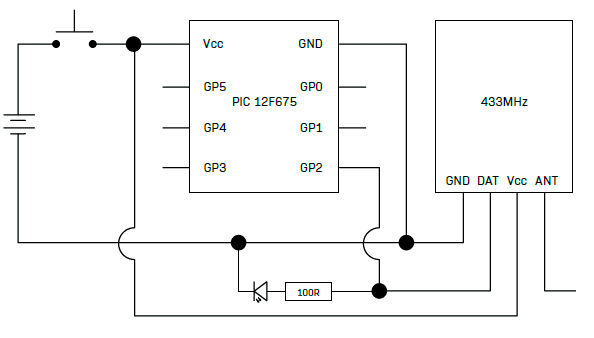
It looks like a 10 year-old has drawn the diagram.
The dots and bridges are bigger than the components!!
No voltage on the battery, and you hardly need a dot for a T junction -
where else can the wire go??
No pin numbering and indication for the 433MHz device.
![]()
![]()
Page 1
Page 2
Page 3
Page 4
Page 5
Page 6
Page 7
Page 8
Page 9
Page 10
Page 11
Page 12
Page 13
Page 14
Page 15
Page 16
Page 17
Page 18
Page 19
Page 20
Page 21
Page 22
Page 23
Page 24
Page 25
Page 26
Page 27
Page 28
Page 29
Page 31