SPOT
Page 1
Page 2
Page 3
Page 4
Page 5
Page 6
Page 7
Page 8
Page 9
SUCCESS
Three mistakes are immediately obvious with this circuit.
Here's another Indian circuit that has not been tested. It is an AND
gate:
This is a
terrible circuit, however if you close swicth !! 2
the LED will turn ON !!
ANOTHER JUNK PROJECT
The circuit is OVER-DESIGNED.
It is a jumble on the PC board and none of the parts are identified.
The designer did not provide any instructions and it is
impossible to put the kit together.
All the parts are identified and the layout corresponds to the
circuit diagram.
This makes it easy to assemble and easy to trouble-shoot and
modify.
Electronics For You Magazine
You think Electronics For You Magazine is popular !!!!
Prototyping:
Here is a prototype on Matrix Board.
Diode Identification:
Placing "+" and "-" on
the symbol of a diode is totally incorrect.
PROJECT ON MATRIX BOARD
Here is another insult to the electronics industry. It comes from an
American magazine. The project has been designed on Matrix Board
and a PCB design has been included in the article, but no photo of
the components on the board. The author did not have the
intelligence to spend $6.00 and get a PC board made and loaded,
before submitting the project for inclusion in the magazine.
BUFFER
Here is a diagram from a Digital Course. Diagram
The value of the inductor creates the timing
of the first half of the cycle and the value of the capacitor creates the
second half of the cycle.
RUNNING LED
THE MISTAKES!
Page 29
Page 10
Page 11
Page 12
Page 13
Page 14
Page 15
Page 16
Page 17
Page 18
Page 19
Page 20
Page 21
Page 22
Page 23
Page 24
Page 25
Page 26
Page 27
Page 28
Page 30
Page 31
![]()
This is the
place where I place all sorts of discussions and helpful advice.
I see so many new designs and new components coming from part's
manufacturers that I wonder how much is actually "taken up" and
incorporated in new designs.
The only way to judge the sales is to look at the inventory provided by
wholesalers and see how
it decreases over a period of time.
You will get quite a shock.
Some of the newest components sell less than 200 units in 18 months.
And many of these have been given away as free samples.
I have said it before, and I will say it again. Be very careful when
choosing components for a project. Many new components are over-priced
and and only available from very few stockists.
I learnt this lesson 20 years ago with a 3-tone doorbell chip. It was
expensive abut produced a very pleasant tone.
Then it became unavailable. The kit had to be deleted. The same with a
speech phoneme chip.
But the embarrassing thing is when you are paying 30 to 50 cents for a
chip and then find it is available on eBay for 3 cents !!!
To make money on a project you have to think of a 20 year life-span.
That's why you should use tried-and-proven components and source them
directly from traders in China or Hong Kong.
Almost everything is available from Chinese markets and the cost will be
10% of wholesale price, with free delivery !!!
The only way to learn electronics is to build a circuit and gt it to
work.
To keep yourself active, you have to be doing this ALL THE TIME.
It is pointless putting circuits into simulation programs as the finer
details of the operation of the circuit will be missing. Things
like motor-boating, feedback, interference between different sections of
the circuit will come as a surprise when you actually build the circuit.
The project will simply NOT WORK.
Do you realise the accuracy of all the cheap digital temperature
displays are about 1% accurate. If you place 6 different displays in the
same location, you will find they vary by less than a degree. How is
this possible when they are not "adjusted" (tested) and use 5% to 10%
components. A thermistor is only 5% and when you add all the 1%
components, you can get any sort of result.
And yet, in the finish, the result is amazing.
On top of that, the digital temperature meters sell for $5.00 and the
single 1.5v cell lasts for 2 years.
It's only when you try to reproduce the circuitry with a
microcontroller, do you realise the enormous complexity and skill
required to deign the circuit. The major problem is taking a very brief
reading every minute because this takes a lot of current.
Talking Electronics has lots of prototyping PC board, matrix board and
boards to take all sorts of chips. These will help you build different
circuits and make them look neat and professional.
You just have to look at the Indian magazines to see how NOT to put
components on a matrix board.
If you are going to make something, make sure it is not an embarrassment
when you show it to others.
Look at the PROTOTYPING article on the left column of the website for
the range of prototyping boards and you can get a handy pack of
components when you visit the 50 - 555 Circuits article.
I have 3 projects on the go all the time and send a panel to the PCB
manufacturers almost every week.
![]()
The whole of Talking Electronics website should have been in the form of a
dictionary.
I did not think it would grow to thousands of articles and contain so much
information.
That's the problem of not knowing the future.
The same occurred with Bill Gates and Microsoft.
He started on a very small platform and his greatest success came from "geeks"
who produced programs for MS systems and initially distributed them via Sunday
"Flea Markets.
Microsoft systems became the number one seller and clones started to come on the
market for under $1,000.
This encouraged Bill Gates to produce the next phase of software "Windows" and
he never looked back.
But the whole system was build on a bed of sand and this became evident when
trojans from the internet started to infect millions of computers.
Internet data should have been stored in a completely walled section and a
window showing what is being downloaded and where it is being stored, should
have been included on everyone's system.
But it's too late now. We have to suffer with a system that gets slower and
slower as the hard drive fills up with junk and deletions.
I wish I had categorized and tabled everything on Talking Electronics website,
so it could be instantly location.
Fortunately w have Google, and this has been done for us. Every paragraph and
image has been spidered and can be looked up instantly by creating a Google
search.
![]()
REVERSE MORTGAGE
Look what will happen to $100,000 borrowed for 15 years @5% as a REVERSE
MORTGAGE.
A Reverse Mortgage is when you own your own house and want to borrow money over
a long period of time.
The amount you have to repay is quite a surprise because the interest you owe
each year is added to the amount you owe and interest is due on the total
amount.
This is called COMPOUNDING and is exactly the same as COMPOUND INTEREST.
In 15 years you owe $208,000 !!!!
The only consolation is the value of the house will rise by $200,000 in many
parts of Australia over a period of 15 years and you may only lose a small
amount.
In some instances you will be able to invest the $100,00 and end up in a winning
state.
You just need to realise the implications of compound interest. It adds about
25% to the payback figure.
![]()
How do you measure SUCCESS?
Everyone wants to be successful.
Maybe it's having 6 children, or 3 wives or an enormous house.
Maybe it's having no money AT ALL.
Maybe it's working for the poor all your life.
Maybe it's having all your children take up Law or Medicine.
There are hundreds of ways to rate success.
And not one fits all.
Some want to be hermits, Some want to celibate and some want to fill their house
with rubbish.
This is all a form of success to different people.
When it is all boiled down, success is getting up in the morning with a clear
conscience, having no debts, having no-one knocking on your door and having no
frustrations.
It's fortunate that electronics can provide you with a life that you can enjoy
and away from conflict, argument and frustration.
It's the most rewarding career you can be involved in and the most challenging.
If you compare electronics with any other field, you will find it has aided and
improved everything to the extent that almost everything is twice the quality
and half the price of 10 years ago.
You just have to look at mobile phones, computers, everyday printing, TV's,
cars, appliances, and everything else you touch.
The one component that has advanced all these items is electronics.
In 1920 the Patent Office in the US was to be closed down because everything had
been invented.
And you are possibly thinking the same now.
If so, you are on the wrong tram.
Just look around you, when you are doing any task and THINK.
There are thousands who cannot do the same task because they are limited in
their capability.
What about an aid or a tool to assist them?
What about an alarm, or a motorised device or a computer program.
That's where a combining of electronics and mechanics can create a new
invention.
I am thinking of new ideas all the time and that's why I release them, so others
can take them up and run with the idea.
That's what this website is all about.
With 22 million visitors already, we are getting new and old visitors through
the site all the time. Some have actually used our circuits to
create their own product.
That's what I call SUCCESS.
![]()
BOOST CIRCUIT USING 555 IC
There is no current-limiting resistor on the LEDs.
Q1 and Q3 are not needed as the 555 has sufficient driving capability to drive
the MOSFET directly.
2u2 on the power supply is not going to be sufficient.
There is a shorting link across R1 and R2 so these components do no change the
frequency of oscillation.
R1 and R2 will have no effect as they change the 100k by a tiny amount when they
are added.
C1 is normally 10n.
What is the purpose of R7?
By creating a negative output, you don't take advantage of the voltage provided
by the supply and the circuit is less efficient.
But the worst part is the layout of the 555.
A circuit diagram is supposed to show the circuit "working" and when the 555 is
shown in the way we have promoted it in the 555 Projects article, you can see
exactly what each lead does. The 555 block above is a "Layout Block" and you
have to take time to work out what each lead does.
![]()
Why?
The lower transistor is an emitter-follower and it will rise so that
about 5v is on the emitter, due to the 10k on the base and 10k on
the emitter creating a voltage divider. This will give a small
current through the 1k to illuminate the LED.
The LED will not be very bright but the brightness will not increase
very much when the top transistor is turned on due to the 4k7 load
resistor.
Here is a simpler circuit that works correctly:
![]()
Another embarrassing junk project from
Electronics For You
January 2017:
The Light Dependent resistor can be connected to a transistor and
the OP-AMP is not needed.
The 7805 can be replaced by a single zener diode.
The 1N4007 diodes should be 1N4004 as 1,000 volt diodes are not
needed.
The TIP 122 is a darling POWER TRANSISTOR. A BC 547 can
be used.
Why have two output driver transistors when the buzzer can be
connected to the transistor operating the relay.
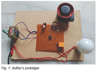
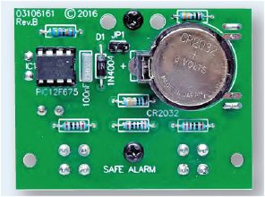
Look at the prototype. The PCB should be cut to size. I have
never seen such as mess. Anyone working in my electronics firm would
"get the sack" on the spot for producing a mess like this.
This is the sort of RUBBISH Electronics For You puts in
their magazine. It shows no quality of presentation and no
understanding of how to design and present a project. Mark:
0 out of 10.
The layout above reminds me of many poorly-laid out PCBs.
Talking Electronics made a policy to lay out the components on a PC
board in almost the same locations as on the circuit diagram.
This was a revolutionary idea. In addition, all the component values
were identified on the board. Previously, all projects in magazines
had R1, R2, C1, C2 and you had to refer to the instructions to put the kit
together.
On top of this, 90% of the projects had no parts identification AT
ALL and it was no wonder very few of the projects were bought and
assembled. The board was just blank with lots of holes. Many boards
sis not have an identification number and 10 years later you forgot
what the board did. Talking Electronics changed all that.
All the other magazines were furious with the concept and tried
desperately to kill the sales of Talking Electronics magazine. In
the end they all failed and went bankrupt. So much for Karma!!
Here is a typical Chinese FM wireless microphone project.
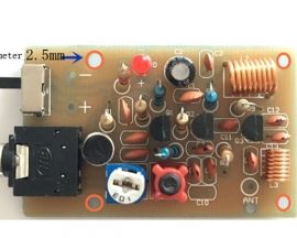
Here is a Talking Electronics kit using a similar circuit: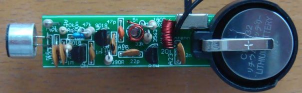
All Talking Electronics projects are a LEARNING EXPERIENCE.
![]()

They are giving it away for FREE !!
The Indians pay 575 Rs for 12 issues and get a free 300 Rs digital
multimeter. That leaves 275 Rs for 12 issues. That is 23
Rs per issue. The postage is 50 Rs to 80 Rs per issue. They
are losing money on each subscription !!!
The only way they get any subscribers is to give the magazine away
at BELOW COST !!!! That proves it is a JUNK MAGAZINE. It
doesn't have any worth.
It's just filled with DREAMTIME. Ideas and things that have been
pilfered from overseas.
If you look at the University electric car you will see it is way
behind the advances of the USA and is costing thousands and lots of
time in development. Of course you have to clean up the smelly
2-stroke cars and motor cycles but who is going to pay for an
electric car when and improved bicycle could not be afforded by any
of the bicycle taxis.
![]()
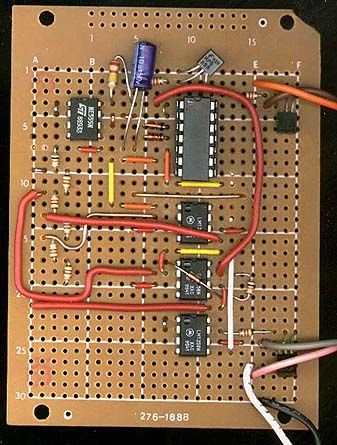
Firstly, I do not know what pattern of tracks are under the board.
The board is so old it is not listed on Radio Shack website.
However the biggest problem with the layout is the amount of board
needed. When designing a PCB, the total areas should be as small as
possible to reduce costs.
This should be done with the prototype so the position of the
components can be transferred directly to the PCB layout to avoid
mistakes.
Maybe two of the three 8-pin chips can be moved over to produce a
rectangular layout with very little wasted space.
Don't worry about the jumpers. A double-sided board will deal with
all the wiring. It is amazing how complex wiring can be placed on a
double-sided board.
Just connect everything together with top and bottom tracks and even
cross some of the tracks. Then go over the board and gradually fix
each of the problems by transferring a track from the top to the
bottom and from bottom to top. It is best to place all the bottom
tracks across the board and the top tracks from top to bottom.
![]()
The only acceptable identification for a diode is the letter "k" to
indicate CATHODE.
There are many times when a diode is not placed in a circuit with
positive on the anode.
![]()
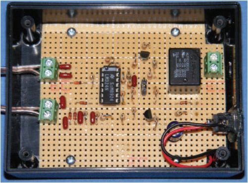
Not only is the board poorly laid out, but 50% of the board is
unused. After 2 months the author has received only 2 replies - with
one asking for a kit of parts. No reply to this question.
I produced a magazine for 20 years and I would not insult my readers
with a layout like the one above.
![]()
How do you expect a beginner to learn if the diagrams are
incorrect???![]()
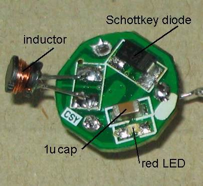
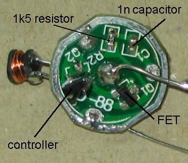
TANK CIRCUIT
One of the first amazing circuits to be "discovered" was the
effect of putting a capacitor across a coil in a circuit that is
oscillating.
This happened over 100 years ago and the "scientist" (called
electrical
pioneers or electrical engineers or famous electrical scientists or
experimenters or inventors or discoverers) had an oscillating circuit that was sending out magnetic
radiation to be picked up at a short distance. The frequency was
produced by a multi-pole generator (alternator) and it was before the
days of actual electronic circuits. The valve had not been invented and
the only semi-conductor was the diode in the form of a lump of crystal
(galena) with a very fine wire (called a cat's whisker) touching the
sensitive spot on the "rock." Even getting wire to make the
circuits and insulating the wire was a new technique with the first wire
being simply cotton wrapped or cotton covered.
So, it was really in the early days of electricity and even the torch
globe had not been invented.
The main things to be invented at the time were spark coils and
capacitors and antenna wires and producing a spark between two balls on
the end of two long antennas.
The apparatus consisted of a coil fed by a high frequency voltage and
this produced electromagnet radiation into the air. At the
receiving end was two antenna wires leading to two balls that were very
close to each other. The transmitter would cause a very small spark to
be produced by the receiver. The inventor found a coil was needed in the
circuit to produce the result he was trying to achieve. The coil
consisted of say 100 turns around a cardboard former similar to a jam
tin. It was quite a large component.
When a capacitor was placed across the coil, the spark at the receiver increased
enormously and if the value of the capacitor was adjusted, the spark became a MAXIMUM.
This was an enormous surprise to the operator as the capacitor was not an
"active" or amplifying component and the coil was not classified as an
active component.
So, how did the output increase with these two simple components?
We now know and the description of how the circuit works is very
complex.
Basically the reason is due to the fact that the two components pass a
signal from one component to the other at a particular frequency and
this frequency is called the "preferred frequency" or "resonant
frequency."
The original circuit produced by the inventor delivered energy to the
surroundings over a
wide band of frequencies and this caused the receiving signal to be only
a fraction of the transmitted signal.
When the capacitor was added, all the energy was concentrated into a
very narrow band and the receiver could be moved much further away. The
improvement could be 100 times better, or more.
The effect was compared to a tank if water that was filled slowly and a
tap allowed a large out-flow when needed. That's how it got the name:
TANK CIRCUIT.
We will use the following circuit to describe how the TANK CIRCUIT
works.
You cannot simply pulse the circuit yourself because the pulse of energy must be delivered at
exactly the right time and for exactly the right duration.
In the circuit below, the TANK CIRCUIT (shown in yellow) controls the
transistor by turning it ON and OFF at exactly the right time so the
TANK CIRCUIT gets exactly the right amount of energy for each cycle.
To make these two shapes equal, the time taken to charge the capacitor
has to be the same for the magnetic energy in the
inductor to be released and passed to the capacitor. In other words, the
capacitive reactance of the capacitor (the energy contained in) has to
be the same as the inductive reactance of the inductor.
The circuit starts with the 4k7 turning ON the transistor.
At the same time the 4p7 will get fully charged via the 330R and
inductor and will have about 3v
across it.
The resistance between the collector and emitter leads will reduce as
the transistor turns ON and this will cause the voltage across the air
trimmer to increase. At the same time the voltage across the coil
(inductor) will increase and current will flow through the inductor and
produce magnetic flux.
This magnetic flux will cut all the turns of the coil and produce a
"back voltage" that will oppose the incoming voltage.
This is because we are trying to deliver current through the inductor at
a faster rate than it is accepted and the inductor produces a back
voltage.
This will prevent
a high current flowing through the inductor and in fact almost no
current will flow through it.
At the same time the voltage on the top lead of the 4p7 will decrease
and since the 4p7 is charged, the lower lead will also drop in value.
This will lower the voltage on the emitter of the transistor.
There are two ways to turn a transistor ON. Either increase the voltage
on the base and keep the emitter from moving or lower the voltage on the
emitter and keep the base fixed.
That's what happens in this case. The 1n capacitor on the base keeps the
base fixed at the frequency at which this circuit operates and as the
collector voltage drops, the emitter is pushed towards the 0v rail.
At the same time the 4p7 is discharging and while the transistor is
turning on more and more, the above conditions apply.
But a point comes when the 4p7 is fully discharged and the transistor is
turned on a fair bit but it is not turning on any more. We don't know
the voltage across the air trimmer but the inductor will have the same
voltage across it and it will be producing the maximum amount of
EXPANDING FLUX. But the rate at which this flux expands is getting less
and less because the transistor is turning on more and more but at a
reduced rate.
Eventually this rate drops to a point where the circuit cannot deliver
expanding flux becomes stationary flux and then it starts to collapse. The collapsing flux cuts
the turns of the inductor and produces a voltage in the OPPOSITE
DIRECTION. This voltage discharges the capacitor and it keeps delivering
energy to the capacitor to charge it in the opposite direction.
The voltage on the collector of the transistor rises and the top lead of
the 4p7 rises and the air trimmer starts to charge. This pulls the bottom lead of
the 4p7 up and the emitter rises too. The reduces the voltage between
the base and emitter leads and it turns the transistor OFF. The
transistor effectively disappears from the circuit and the voltage on
the lower lead of the air-trimmer rises and can rise to a voltage higher
than the 3v supply.
The magnetic flux (energy) charges the air trimmer and 4p7 and
eventually the 4p7 is charged and it no longer keeps pulling the emitter
lead "up."
The voltage on the emitter lead reduces and the voltage between the base
and emitter increases and this starts to turn ON the transistor to
create the next cycle.![]()
Here is another junk circuit from
Electronics For You February
2017:
It has 81 LEDs in 9 rows and 9 columns.
The LEDs are turned on ONE AT A TIME and this means it takes 81 cycles
before the first LED is illuminated the second time. You can imagine how
dull the screen will be with a terrible scanning like this.
But the biggest technical mistake is the 220R (R1) in the collector of
the first transistor.
When T10 turns ON, the voltage on the top (anode ) of the LED will be
0.5v + 2.3v (for a yellow LED) = 2.8v.
The emitter will not rise above 2.8v and thus the base will not rise
above 2.8v + 0.7v = 3.5v.
But the 4017 will try to pull the base up to about 4.5v as the base is
connected directly to the output. So we have a conflict.
What happens? Current of about 5mA is delivered to the LED via the output of
the 4017 and the voltage on the output drops to about 3.5v
A current of about 10mA will flow through the 220R resistor but the
whole circuit is badly designed. The transistor is turned ON fully, but
the base should not draw current when in a correctly-designed
emitter-follower circuit. A very bad technical mistake. The 220R should be
in the emitter lead.
The "Assistant Professor" has absolutely no ideas about electronics.
It was designed by:
Pamarthi Kanakaraja, assistant professor. Usha Rama College of
Engineering and Technology, Andhra Pradesh India.
I pity all those students going through any of his courses. You should demand your money back.
![]()
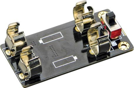
BATTERY CHARGER
Here is another bad circuit from
Electronics For You February
2017:
It is a battery charger that is connected directly to the mains.
This means it will have leads and alligator clips exposed, with 300v
potential.
But the real issue is the 1R resistors. What effect will they have
on protecting ANYTHING?
What voltage will appear across the connections of CON2?
About 2v What will this tell you????
What voltage will appear across the connections of CON3?
About 2v What will this tell you????
![]()
Another untried circuit from "Professor" Mohan Kumar:
Some LEDs will come on at a voltage lower than the recognised
"characteristic voltage" but you cannot take this into consideration
when designing a circuit.
Take the green LED for example. 10v is dropped across the zener and 2.3v
across the LED. But the LED will not illuminate when the supply is 12.3v
because there is no voltage across the 470R and thus no current will
flow. If we increase the voltage to 13.3v, 1v will be dropped across the
470R and 2mA will flow. Thus the value of 11.8v on the circuit is
incorrect.
Obviously he has not tested the circuit and we have proved he never
tests any of his circuits. He just puts them out and makes a fool of
himself. He is the worst design-engineer in India. None of his
circuits work.
![]()
LASER RECEIVER
The secret to being a good design engineer is knowing how and what to
design and the characteristics of each of the components you are using.
In the circuit above, the the two LDRs' can be connected directly to the
555 without any transistors. This is something the two design engineers
should have done before putting the project into Electronics For You.
But neither the magazine or the two students are qualifies to do this
research and that's why the magazine published such junk projects.
The circuit below will achieve the same result as the one above:
Two laser beam are focused on the two LDR's and when an object passes both beams at the same time, the alarm is activated.
![]()
SURFACE MOUNT DC to DC "CUBE"
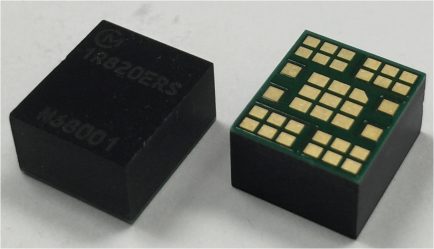
Here is the latest DC to DC "cube."
It might be a wonderful design but mounting it on PC board for a
prototype will be very difficult.
And diagnosing any problems when the project is ready for shipping will
also be be a disaster.
You cannot get to the pins under the cube and you don't know if they are
all soldered correctly. You don't know were a problem will occur.
You are just asking for trouble when you include a component that you
cannot thoroughly test and check. There are plenty of DC to DC
converters and if you have to use a through-hole component, it will be a
hassle-free alternative.
There are two more pointers you have to take into consideration.
Recently introduced components are very expensive and may be in limited
quantities. But more important is the fact that many of these items go
out of production and you are left with a product that has to be
re-designed. This has happened to the author on many occasions and has
terminated a good-selling kit.
![]()
ALARM
Normally I don't find much to highlight from Silicon Chip Magazine because they don't produce much in the way of basic projects. But when I offered to supply them with FREE projects each month, they flatly refused the offer, basically they knew I had a very large following and they were afraid I would "steal the show." They have not produced a singe simple project for beginners for the past 5 years and it is no wonder their sales have dropped to less than 6,500. It is probably much less than this because the local shopping centre sold 105 copies per month and now they sell 15. And all the sub-news agencies have gone.
However they manage to scrape by, by selling all their content to Everyday Practical Electronics in the UK and it is dumped in their magazine, exactly 12 months later !!
Silicon Chip tried to make some vague stupid comments about a couple of my projects and that was when I suddenly realised Leo Simpson had absolutely no understanding of electronics. And when I contacted a number of acquaintances, they confirmed the fact that he has never presented anything technical. How you can run an electronics magazine and not know anything about the content. This is a skill of deception.
Here is a project that shows a complete lack of understanding:

The piezo has less than 5v across and its output will be similar to a
MUSICAL BIRTHDAY CARD.
I tried 11v on my HANDY TIMER
project and you could not hear the beep in the next room. I added
an inductor and now you can hear the beep with the door closed !!
I used the push-switches shown in the photo above in some of my projects
15 years ago and they are such poor
quality they don't make contact after a few presses. They are
RUBBISH !
Silicon Chip have always used 1% resistors and they cover up the value
on the PCB so you don't know if the correct resistor has been fitted.
They obviously don't get any feedback from readers, because this
absurdity has been dished out for the past 20 years.
And when you go to the EPE PCB website, the PCB is not yet available.
The website is 2 months behind !!!
When you go to the Silicon Chip website, they want $5.00 for the PCB and
$13.00 for the chip. Imagine how much the whole kit will cost by the
time you pay delivery costs from 3 different suppliers !!!
Then you look at delivery time and find they have NO PCB's IN STOCK !!!
What a joke.
Now you can see why they hated TALKING ELECTRONICS. I
provided same day service to over 250 kits and sold more than 300,000
kits over a period of 25 years.
No magazine offered anything like the service, feedback, reliability and
back-up.
Talking Electronics is the only website with backup and assistance to
all the kits they have designed. And no-one has complained about the
price. If they do, they get 1kg of kits on their doorstep, FOR FREE !!
![]()
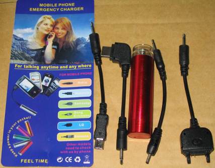
WHAT !!!!
They might be very clever and save one or two cells, but a cell costs less than $1.00 for 1.5v and $2.50 for a 3.7v cell.
To produce 5v, you just need 4 x AA cells and a diode. This will reduce the voltage to 5.4v and the voltage will drop slightly as the cells get used.
The project below costs more than $12.00 and $8.00 delivery, just to get 5v from 2 cells.