SPOT
Page 1
Page 2
Page 3
Page 4
Page 5
Page 6
Page 7
Page 8
Page 9
STATISTICS
Cybersquatting. Cybersquatting (also known as domain squatting), according to
the United States federal law known as the Anticybersquatting Consumer
Protection Act, is registering, trafficking in, or using an Internet domain name
with bad faith intent to profit from the sale of the website.
He has bought the name for less than $10.00 from GoDaddy in the hope that some idiot will
buy it from him for an inflated price.
Here is his email:
Hi,
I asked him how much he wanted.
I told him I would pay $14.
Fortunately he has had no offers and will be stuck with the name until it dies.
This will be wonderful to see. Out of the 22 million visitors, no-one has shown
me any of my "web gimmicks" unless he is talking about the tricky circuits and
projects I have produced.
If electronic circuits could be explained like this:
Everyone would be able to understand them.
Pearls of Wisdom
BRIDGE
This bridge might work or it may not.
This circuit can be simplified by removing the two lower transistors and
adding the red signal diode.
OP AMP
Can you see purpose of the 10k pot?
2 DIGIT COUNTER
Here's something new!!! It appears the block diagram of the
CD4026 is back-to-front in the circuit diagram above. You are looking at
the underside of the chip!!!
CROSSING LIGHTS
The circuit above can be simplified:
MAGIC EYE
Two faults with this circuit.
NUMBERS GAME
Three faults with this circuit.
MOTOR CONTROLLER
Look at the circuit carefully and you will see the L293D chip is not
needed. The 555 is capable of delivering 200mA and if the motor needs up
to 200mA, it can be connected to the DPDT switch and the L293D removed.
3 TRANSISTOR AMPLIFIER
This circuit was found on an electronics forum where the person wanted
to reduce the distortion.
The circuit works but the description is totally incorrect. The circuit
is NOT a Relaxation Oscillator. It is a FEEDBACK OSCILLATOR
R1 and C1 form the timing components
of the oscillator and with a 330 K resistor (R1) and 10 uF capacitor
(C1) the LED blinks around
1 Hz rate. This is correct.
So T1 and T2 turn off. This turns off LED. Again C1 starts charging and
the cycle repeats making the LED blink continuously.
BATTERY MONITOR by D Mohankumar
The circuit will activate when the battery goes below 8v. This is too
low for the 12v battery.
Look at this faulty description:
POWER SUPPLY by D Mohankumar
Every circuit by Mohankumar contains faults.
POWERING A LED by D Mohankumar
When will we get rid of this idiot Mohnakumar.
CAPACITOR-FED POWER SUPPLY
by D Mohankumar
Here is a capacitor-fed power supply by D Mohankumar.
He says: When a capacitor (C) and a resistor (R) are
connected to AC lines, a constant current can be maintained
through the resistor (R) so long as the �Reactance� of the
Capacitor is greater than the �resistance� of the Resistor.
Here's a Joule Thief circuit using an inductor. The position of
the 1N4148 looks to be rather unusual and I had to look at the circuit
for 5 minutes before I realised it was preventing the 10u
discharging via the inductor and so I re-positioned it to show exactly
what it was doing.
Every component needs to be placed in a position on a circuit so its
function is immediately recognised.
The next change to the circuit is the BC557. It is not needed. The photo-cell can be re-positioned and the transistor removed to create the
following circuit:
The circuit above is a really bad design..
This circuit produces a brighter illumination from TWO LEDs while using
the same current as the previous circuit.
POWER SUPPLY by D Mohankumar
Only 2 faults with this circuit.
SUNSET LAMP by D Mohankumar
The circuit is over-designed. It just needs 2 transistors:
The first circuit takes 10mA via the 555 all the time. The second
circuit takes less current.
BED ALARM
And he has used a Force Sense Resistor to detect when a child climbs out of a bad.
Conductive foam sheets
THE MISTAKES!
Page 25
Page 10
Page 11
Page 12
Page 13
Page 14
Page 15
Page 16
Page 17
Page 18
Page 19
Page 20
Page 21
Page 22
Page 23
Page 24
Page 26
Page 27
Page 28
Page 29
Page 30
![]() Some readers have asked why I don't include any formulas in the articles.
Some readers have asked why I don't include any formulas in the articles.
It's simple.
I would lose 99% of the readers.
I am not trying to make you a University scholar.
You can find all the mathematical approaches to electronics on the web and
in every text book.
It's pointless doubling-up on what's already there.
But the funny thing is this: many of those providing answers to simple
problems on the electronics forums can answer the mathematical questions but
stumble terribly when trying to provide a circuit to perform a simple task.
They over-design, use an op-amp when a simple transistor will work perfectly
and use component-values that are not in the normal range.
You can see instantly they have never deigned a circuit in their life, and
relied on application notes to get them through.
That's why there are so few text books with practical applications.
As soon as they include a circuit that has not been tested, you can see
their inability to "see" a circuit working.
This is the basis to what we are teaching at Talking Electronics.
The skill to be able to SEE a circuit working and thus fix, mend, design and
modify circuits.
I know this is a skill, but it is the answer to being able to design.
It comes well-ahead of being able to carry out the mathematics as you are
in-effect carrying out the mathematics "in your head" by assessing the
current and voltage at each point in a circuit by looking at the resistor
and capacitor values.
That's why this section on Spot The Mistake is so important.
It shows you how to spot a Mistake and see how and why others have made
mistakes in their design.
It is an area that no-one has thought-of before.
We started this concept 30years ago when we included a section IF IT DOESN'T
WORK, in all the projects.
Every project in a magazine expects the project will work.
But what if it doesn't work??
The only time you start to learn electronic is when you have to fix
something.
And that's where most authors fall down.
They don't have the engineering skills to work through a project, using some
part of the project as a piece of "test equipment."
It might be a LED or a speaker, giving a sound or flashing.
Or you can use a multi-meter or logic probe to diagnose the problem.
But the important point is NOT TO GIVE UP.
![]()
The mobile phone and the internet has increased communication between people
over 1,000%. Whereas a few landline calls and letters were the only
communication, we now have instant messaging where you can contact any one
and any business anywhere throughout the world, in a matter of seconds.
The only problem is the sorting through the spam to get the actual requests
from readers.
Sometimes, the bulk elimination of junk emails deletes a genuine request,
but that's the price you have to pay for progress.
There are a lot more Chinese kits coming on the market at prices below the
cost of components and these kits are very good value.
The only problem is the instructions.
Many do not come with instructions, especially set-up details and this is
holding-back their sales.
Most of the kits work very well, although some could be improved.
It's only through the universality of electronics that it has exploded
throughout the world. Imagine if we had 4 different resistor colour codes or
5 different component spacings.
We would be like the car industry, where nothing fits, from one model to
another or one make to another.
Electronics would be as expensive as a BMW.
And if component symbols were a jumble, we would never be able to produce
these Spot The Mistakes pages. ![]()
Scientists (including electronics engineers)
tend to disregard statistics as a "voo doo hypothetical imaginary invention" to
con the unsuspecting.
Statistics is the generation of figures and numbers from one source and looking
at the trend to apply the same reasoning to another identical or similar
situation.
Take for instance, the number of readers who look at Talking Electronics
transistor articles each day. Out of the 100,000 different readers who have
visited the website, we get exactly 276 readers who look at the transistor
article each day.
And the same applies to the 55 article. The rise and fall is very small.
Now we take EVERYDAY PRACTICAL ELECTRONICS with their TEACHIN-2015 set of
articles. They say the series has been very successful.
But when you go to their website and look at the Forum, you will not find one
enquiry about the series in the past 6 months.
In previous years the Forum has received several hundred enquiries.
What has happened?
Electronics has died.
The percentage of enthusiasm and construction has fallen from an initial 100%
(1940 to 1980) to less than 10%, maybe 5%, maybe 2%.
Other things have taken over. Apps, games, 3D TV, Face book, have reached
astronomical proportions where people are glued to their seat for 10 hours a day
interacting on trivial matters with others in their group.
The decline in the interest in science has reached such a low point that some
governments are now starting to tackle the problem by allocating new funding to
this area.
I don't know whether this is necessary as great inventions and improvements will
always come from the most unsuspecting quarters, however it is important to
remind everyone that science is one of the most important studies in the
education of man.
It was in the fore, 50 years ago with every school being provided with 2 new
science classrooms and now it has hit the headlines with the theme of teaching
"coding."
![]()
I got an email today from an Indian person who is obviously a
Cybersquatter.
We are selling domain name
MyMetalDetector.com,
Would you be interested in acquiring this
Domain Name?
Please Advise
Kind Regards,
Chandan Mishra
Thanks for reply
We are just looking $400 for it
He said that was too low.
Then he replied with the auction from GoGaddy where NO BIDS had been recorded
and his reserve price was $20.00
Here is the link to the "auction:"
https://in.auctions.godaddy.com/trpItemListing.aspx?&miid=167759182
What a cheek he had. Trying to get $400 for a website that anyone could buy for
$1.99 plus a few costs.
Cyber squatting is considered a crime in the US when a person simply buys a
domain with the intention of preventing another "genuine" person gaining the
domain name, and then trying to sell it for an inflated price.
This is clearly what Chandan Mishra
Long gone are the days when websites had any value.
Visitors look on Google for a website and don't type in a URL because the
slightest mistake will go to the wrong domain.
He has asked for this EXPOSURE to be deleted. This I will not do as he is
clearly a FRAUDSTER.
Even selling the website for $20.00 contravenes the act. The act only states the
fraudulent INTENTION is punishable. And the act is CYBER SQUATTING.
It's a pity he does not reside in the US.
![]()
After reading many of your web gimmicks, we - a group of young Indian
circuit designers - plan to launch a website against your talking electronics.
Along the same lines, one of the editors of Electronics For You, has replied to
my statement that many of the circuits in the their magazine DO NOT WORK or have
very poor design-features.
He comes up with stupid statements such as "All the circuits have been tested"
and tried to get away with some garbled idea that the circuits are presented for
experimenters to "tinker with" and improve.
I have never heard such nonsense and if this were said in any Australian
magazine, the editor would be hounded off the "reading-list."
The simple fact is this: Indians have a very poor understanding of electronics
and you can see this in their projects and writings.
Projects are presented as the "author's prototype" on breadboard or matrix
board, with wires and leads going everywhere. It's just a jumble.
Many of the projects don't have a printed circuit board or the availability of a
kit of components.
Kits and Spares is the only supplier of some of the kits and they want $50.00
postage for a $5.00 kit !!!
There has NEVER been an electronics instructional article in EFY magazine and
the details of the operation of most circuits is very minimal.
In some cases they devote less than 6 pages of the whole magazine, to
construction.
It is glaringly obvious that they are struggling to present technical
information and the Indian hobbyist is suffering enormously.
They have never challenged any of the comments I have made nor provided me with
the email address of any of the authors of the projects, so I can correct their
work.
The editors of the magazine have never heard of "DESIGN CONCEPTS" where the
value of a component is determined by the job it is intended to do.
Putting 0.22u on a 100MHz line or 10 ohm in a 300mA line shows a complete lack
of electronics understanding.
This is the sort of thing we are exposing in these pages and "SPOT THE MISTAKES"
allows us to cover all those things that don't fit into any of the other pages.
That's why we have reached page 25 !!
![]()
The only way to avoid debt is save money from the first day you start
work.
And the second way is to have a trade or
qualification.
 It
doesn't matter if it is electrical, electronic, mechanical or building, welding,
painting or brick-laying.
It
doesn't matter if it is electrical, electronic, mechanical or building, welding,
painting or brick-laying.
Build up a skill in 1, 2 or 3 fields and you will have an inside/outside job and
business/career for the rest of your life.
It's only those who waste their life from 14 to 18 that suffer the rest of their
time with patchy employment.
Of course it would be wonderful to be a lawyer, doctor, dentist, investment
consultant, physiatrist or politician, but those lucky breaks are only available
to very few.
The rest of us have to get educated the hard way and make a success of life in
these extremely hard times.
Business, work and opportunities are actually 5 times more difficult to achieve
than 30 years ago.
You have to be 3 times smarter than the previous generation to get ahead.
The reason is the conglomerates have taken over nearly all the lucrative areas
of business including discount selling and enormous construction ventures,
Even the areas for promoting electronics are miniscule compared to 30 years ago.
That's why you have to be so clever.
![]()

![]()
1. 42.7 percent of all statistics are made up on the spot.
2. 99 percent of lawyers give the rest a bad name.
3. Remember, half the people you know are below average.
4. He who laughs last, thinks slowest.
5. The early bird may get the worm, but the second mouse gets the cheese
in the trap.
6. Support bacteria. They're the only culture some people have.
7. A clear conscience is usually the sign of a bad memory.
8. Change is inevitable, except from vending machines.
9. How many of you believe in psycho-kinesis? Raise my hand.
10. When everything is coming your way, you're in the wrong lane.
11. Hard work pays off in the future. Laziness pays off now.
12. On the other hand, you have different fingers.
13. What happens if you get scared half to death, twice?
14. Why do psychics have to ask you for your name?
15. Inside every older person is a younger person wondering, "What the
heck happened?"
16. Light travels faster than sound. That's why some people appear
bright until you hear them speak.
17. Life isn't like a box of chocolates. It's more like a jar of
jalapenos. What you do today, might burn you tomorrow.
![]()
There are two things you have to remember when designing a bridge.
A motor takes 10 times more current when starting, than when it is at full RPM
and the current can increase 5 -10 times when the motor is under load.
The transistors in the bridge have to deliver this current and a BC547 is only
capable of delivering 100mA under the best conditions.
It is difficult to know how much current each transistor is capable of
delivering in the bridge circuit above, however the top two transistors are
EMITTER FOLLOWERS and the 510ohm resistor in the base is effectively reduced by
100 by the gain of the transistor to become equivalent to 5 ohms.
The resistance (impedance) of a motor is about 5 ohms and this will reduce the
current. The transistor in this circuit will have the biggest effect on
reducing the current-flow to a maximum of about 100mA.
![]()
The two lower transistors are simply turning the output ON and OFF and this can
be done with the red diode.
This diode is called a GATING DIODE and prevents the output transistors
delivering a signal to the speaker when the cathode of the diode is taken to 0v.
The two lower transistors and two resistors are removed.
This is the accepted way to gate the output. It is called "AND" gating. ![]()
If you turn the pot towards the 5v rail, the LED will illuminate. A
small rotation of the pot will reduce the brightness considerably.
So we will turn it to the other end.
When the pot is fully turned to the output of the Op-amp, the circuit
will work, but the slightest rotation of the pot will reduce the
brightness considerably.
What is the purpose of the 10k pot?![]()
This is NOT how to represent a chip.
All chips are looked-at from the top and pin 1 is always on the left of
the diagram.
If you don't have a standard way to represent things in electronics, it
gets very confusing.
You will also notice pin 8 of the chip is not connected. The chip
will not work with pin 8 not connected to 0v rail.
![]()
![]()
1. The 1k supply resistor and 1k resistor to the base of the transistor
will form a voltage divider that will only deliver 2.5v to the chip.
2. When pin 3 of the 555 goes HIGH, the UM66 music chip will see a
reverse voltage as the "earth pin" will see 5v and the supply pin will
see about 2.5v. This may produce a high current through the chip. I have
not tried connecting the chip around the wrong way !!!
![]()
1. I do not know how the TOUCH STOP works. The output of pin
3 of the 555 is a low impedance pin so touching the wire will have no
effect.
2. No current limiting resistor for the LEDs on the CD4017. This
resistor is not essential as the chip can only deliver about 10mA from
an output line, but adding the resistor puts less strain on the FETs
inside the chip.
3. No current-limiting resistors between the CD4033 and the 7-segment
display. Without the resistors, the LEDs will be extra bright and the
additional current may put a strain on the CD4033 IC.
The circuit is designed by an incompetent hobbyist and should be removed
from the web.
![]()
The L293D loses 1v when the output is HIGH and 1v on the LOW output.
This means the maximum output voltage will be 3v.
If the DPDT switch is placed after the L293D IC, the voltage will be 4v.
![]()
There were a lot of replies including changing the 100R for diodes and
adding resistors to reduce the gain.
But NO-ONE outlined the real reason for the distortion.
The reason for the distortion is the fact that the output transistors
are connected in an arrangement called PUSH PULL.
When the first transistor is not turned on, the BC337 transistor is
pulled HIGH by the 680R resistor. This action pulls the 470u
electrolytic HIGH and and current flows through the 8R load.
During this time the 470U electrolytic charges a small amount.
When the first transistor turns ON, it pulls the BC327 down with 100
times more strength (current) than the current flowing through the
collector-emitter terminals of the BC547.
The BC547 is equal to about 47R resistor.
This means the "pulling down" is equal to 47R and the "pulling up" is
680R.
Since these are very different values, the current in the 8R load is
limited to the weakest part of the cycle - the 680R and this has
the greatest effect on producing a faulty output.
Even though one part of the cycle is 15 times more powerful than the
other, the electrolytic can only charge (or rise) to the amount offered
by the 680R portion of the cycle and the strong part of the cycle simply
discharges the electrolytic.
But it can discharge it much faster than the charging part of the cycle
and this contributes to the distortion.
![]()
LED FLASHER by D Mohankumar
LED FLASHER
Here is his description:
The circuit is a simple Relaxation
oscillator using two complementary transistors BC 547 and BC 557.
Capacitor C1 is doing the trick and it gives the positive feedback to
start the oscillation of T1 and T2.
This is INCORRECT. R1 starts the circuit working.
When power is applied, C1 starts charging via R1. When C1 fully charges,
NO. C1 charges to 0.6v to starts to turn on the first
transistor. T1 is an emitter-follower and it rises. C1 has to keep
charging to keepT1 turned ON.
T1 conducts and pulls the base of T2 to ground potential and it also
conducts. The collector of T2 gives power to LED and it lights. At the
same time C1 discharges through R3. This is INCORRECT. The
voltage on the top of R3 rises and this pushes all the charge in C1 into
the base of T1 to keep it turned on. Eventually all the charge is
removed and T1 starts to turn OFF.
![]()
The resistors can be 0.25 watt
Zener diode is a special kind of diode that conducts only when it gets a
voltage more than its rated voltage. For example, a 7.5 Volt Zener diode
used in the circuit requires more than 8.5 volts for its smooth
conduction. That means, the Zener requires + 1 or 1.5 volt excess than
its rated value for proper conduction.
What RUBBISH !!
Why have a 7.5v zener diode if it works at 8.5v ???
A zener diode produces a voltage across it VERY CLOSE to its printed
value. That's why you can create an accurate 12v supply when using
a 12v zener diode.
What Indian school of electronics did Professor Mohankumar teach at
?????
![]()
Look at this Power Supply circuit.
The purpose of any electrolytic in a power supply is to store energy and
reduce the ripple. That's what the electrolytic in this circuit is
doing.
To take advantage of its stored energy, you must connect directly across
the electrolytic. The 470R resistor is NOT NEEDED. It turns this power
supply into a USELESS POWER SUPPLY.
The current through the 9v zener is 35mA.
As soon as you put a load as little as 250 ohms on the output, the
current through the LOAD will be 35mA and any further LOAD will start to
reduce the output voltage.
If you put extra LOAD on the circuit, the current will not increase but
the output voltage will reduce.
What happens is this: A 250R load in series with 470R produces a voltage
of 9v at their join.
As soon as you reduce the 250R, the zener drops out of regulation and
the voltage across the LOAD decreases.
In his article, he tests the output of the power supply WITHOUT A LOAD
and comes up with stupid decisions about how much current will be
available at the output.
Tell him to learn how to test a circuit. I am sick of emailing him. I
have emailed him for the past 3 years. He never listens.
Mohankumar does not check or test any of his circuits CORRECTLY and he
keeps putting his RUBBISH on the web. He has been told to test his
circuits and all his Indian friends keep supporting him, saying how
wonderful his circuits are. You decide.
![]()
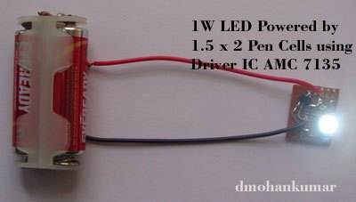
Here he is with more of his RUBBISH.
The image shows a white LED powered from 3v via an IC AMC 7135.
The AMC 7135 is a constant current chip capable of delivering a constant
350mA to a 1wattLED.
A 1 watt white LED has a characteristic voltage across it when the
current is more than about 100mA of about 3.2v and this increases to
about 3.6v when 350mA flows.
But when you reduce the current to less than 50mA, the characteristic
voltage across the LED is about 3v.
This means you can directly supply the LED with 3v and about 20mA flows.
YOU DO NOT NEED THE AMC 7135 IC !!!!
The IC just makes the LED dimmer as it drops about 120mV !!!
This circuit that the idiot Mohnakumar has produced is absolute RUBBISH
!!!!
I don't know how he can get everything SO WRONG !!!!
Just because the IC will work down to 2.7v, Mohnakumar thinks you
can drive a 1 watt LED from 2.7v. But most 1 watt LEDs are white
and they have a characteristic voltage across them of 3.6v.
When will he learn ????![]()
In his
article he tries to explain how a capacitor passes a certain current
according to its value.
But he still has no idea how the circuit works. Look at the
circuit above.
He correctly states the current delivered by a 105
(1u) capacitor will be 60mA to 70mA, BUT he also states the
output voltage will be 30v to40v.
How does he come up with this value ????
The output voltage of a capacitor-fed power supply will be 340v
DC (if nothing is connected to the output) and the LOAD
determines the actual voltage.
The load is the LED and 1k resistor. If 70mA is available, ALL
this current will flow through the 1k resistor and the voltage
developed across it will be 70v !!!!!
The current through the LED will be 70mA and the LED WILL
BLOW UP. !!!!!!
That's how little Professor Mohankumar knows about electronics
!!!!
He is so dangerous he should not be on the web. It's
IDIOTS like him that give the web a bad name.
He is totally uneducated and does not understand the simplest
electrical engineering problem.
Here is more RUBBISH from him:
What RUBBISH.
Suppose the resistance of R is LOW and 60mA flows through
it.
Suppose R is increased and 125v appears across it. The current
will be 30mA.
If we go to the extreme and use a very high value for R, the
voltage across R will be 230v and NO CURRENT WILL FLOW.
This is simple to understand. A high value LOAD is just like NO
load AT ALL and the output voltage will rise.
If you have NO load, it means NO current will flow through the
capacitor and thus NO voltage will be dropped across it. The
capacitor is really like a 10k resistor for part of the cycle
and if NO current flows through the 10k resistor, there will be
NO voltage dropped across it and thus the output voltage will be
as high as the input voltage.
Professor Mohankumar did not even bother to look at the logics
of the circuit and came up with an absurd statement. This is why he
should not be on the web !!! He is a FRAUD. A
person with NO electronics ability masquerading as a
professional. He doesn't even make corrections to his projects
after he is informed of his mistakes. That's the CRIMINAL part.
He KNOWS he is supplying faulty information.
The fact is this: As the output voltage increases, the current
capability of the circuit decreases, but since you have a large
voltage available, this reduction in current is not really
noticed.
![]()
Text books just give you examples of circuits that work.
We give you examples of circuits THAT DON'T WORK.
You learn more from a FAULTY circuit than a circuit that works.
It was only after starting to fix faulty black and white TV sets
that I realised by degree in electronics was almost worthless.
The attitude of the lecturer was this: ANYTHING YOU BUILD
WILL WORK !!!! What a BIG mistake.
![]()
That's why you have to draw a circuit using a placement and CONVENTION that everyone
recognises.
I can now see how the circuit works::
It does not have what we call REGENERATION.
Regeneration is a feature of a circuit that uses positive feedback to
improve the amplitude of the output. In the circuit above, the output
transistor is turned on via the 1k resistor when the first transistor is
turned off.
And when the first transistors is turned ON, the second transistor is
turned OFF but the current through the 1k is wasted.
In the circuit below, the transistor gets turned ON a little via the
2k7 and then it gets turned ON more and more by the voltage produced in
the 40 turn winding. The 10n is to stop the current generated by
the feedback winding being lost in the 2k7. Thus the extra current fed
into the base of the second transistor is only produced during the time
when it is needed.
When the circuit is turned OFF, the voltage
in the 40 turn winding is produced in the opposite direction and no
current flows into the 2k7, due to the capacitor, again. Thus this type of arrangement is much more
efficient than using a 1k resistor and shorting the current from it to
0v rail, to divert it from the base of the output transistor. This is
like shorting your incoming 230v mains to ground so you don't get any
electricity when you don't want it !!!
It might seem insignificant, but when you understand these
things, you can see how brilliant designers and engineers have created
DC to DC power supplies with 90% efficiency and CFL's with 95% efficiency.
When you go from 10mW to 10 watts to 100 watts to 10,000 watts, getting
rid of unwanted heat is a big problem.
And the understanding all starts with a 10mW inverter..
![]()
The 12v unregulated will be about 16v and the 3v to 3.8v will be 2.9v to
3.1v
![]()
The diode across the relay is not needed because the transistor switches
at a very slow rate.
The 100u is in a bad position in the first circuit. It has a much bigger
effect in the second circuit and can be replaced with 10u.
If
Professor Mohankumar knew anything about circuit design, how
would not make these mistakes.
![]()
 Here's another totally impractical project from T.K.HAREENDRAN
He has used a 28 pin microcontroller where an 8 pin
chip will do the job.
He has used exotic diodes, whereas a simple 1N4004 will do the job and a
regulator that you will have to buy from a large wholesaler.
He obviously gets his parts for FREE by claiming to be a "writer" and
expects INDIAN hobbyists to buy all this expensive stuff to make a
simple BED ALARM.
My father made the same thing 60 years ago with a vibration detector
under my bed that makes contacts when I climbed out of the bed. He used
a front-door bell that rang and vibrated when I made a lot of movement.
Firstly, there was no electronics 60 years ago, and a simple vibrating
weight and bell is all you need for this project. Think outside the
square or "think outside the box" and you will realise how stupid this
project is.
He says to place the resistor near the child's shoulder to detect the load abut
if you have ever tried to detect a load in a bad you will find this is a very
difficult thing to do. He has obviously never tested this circuit as a sensor like this is USELESS.
You need a large sensor made from two sheets of aluminium cooking foil
and placed between the sheets is a think layer of black resistance foam
as used when placing sensitive chips in foam. This will detect a much
larger area.

![]()
VOLTAGE MONITOR by D Mohankumar
The current through the LED will be more than 100mA. The IC can only
output 25mA !!!
Ohm's Law
Here is another untested circuit from the same IDIOT:
What does R2 do ???
![]()
Professor Mohankumar doesn't
even understand basic mathematics.
He is the second Indian "Professor" to fail basic mathematics.
The terms Vs - Vf must be in brackets so that you work out the answer of
(Vs - Vf) and place the answer in the bracket and then perform the
division.
![]()
LED Current by D Mohankumar
Professor Mohankumar says:
Current through a LED must be between 10 to 25 Milli Ampere.
This is NOT true. Some ultra bright red LEDs are "too bright" if
more than 3mA flows.
LEDs are becoming more and more efficient and a current as small one to
five mA will be sufficient.
You need to buy and test each LED before deciding on the current
required.
Look at this rubbish:
The new type 0.5 and 1 watt White LED requires 100-350 mA current.
Forward voltage drop is 3.6v. So the value of the resistor must be very
low. Since high current flows through the resistor, the wattage of
resistor must be � or 1 watt otherwise, the resistor will heat up and
burn. Suppose the current required is 250 mA, then the resistor is
R = (Vs - Vf )/ If = (12 � 3.6) / 0.25 A = 8.4 / 0.25 A = 33.6 Ohms. Use
33 Ohms 1 watt resistor
He has not bothered to work out the wattage lost in the resistor
!!
The wattage lost in the resistor is:
Power = (V x V) / 33
= (8.4 x 8.4) / 33
= 2.14 watts!!
or:
Power = V x I
= 8.4 x .25
= 2.1 watts !!
He has absolutely no idea what he is doing.
I could "see" the wattage lost in the resistor is more than one watt
before starting to work out the actual value. That's why I questioned
the answer. And I was right.
That's the skill you have to have. Instead of wasting the energy in a
resistor, you should add an extra LED and use the energy as
illumination.
Putting a single LED on 12v is very inefficient and wasteful.
![]()
Zener Calculations by D Mohankumar
Professor Mohankumar doesn't
understand how a zener supply works. And he doesn't understand how to
explain its operation.
HEAT SENSOR
The original circuit had 10k for the voltage divider resistor for the
NTC thermistor.
CRYSTAL RADIO
The crystal earpiece is made with a piece of crystal with two wires
attached. When a voltage is applied to the wires, the crystal changes
shape.
BLOWN FUSE
Firstly, the input voltage can come from a 9v supply with a capability
of 500mA or 1 amp. Any current capability over about 100mA will work
with this circuit.
He has chosen 120 ohms for the current-limiting resistor and this will
allow 32.5mA to flow in the zener.
(9 - 5.1) / 120 = 32.5mA
The wattage rating for the zener must allow for the situation where the
load is removed and ALL the current flows through the zener.
The zener rating must be: 5.1 x 32.5 mW = 165mW
Where does he get 500mW ????
Select 400mW zener.
The output current can range from 0mA up to 25mA and this current will
depend on the LOAD. The zener has no control over the output current.
The output current robs (takes) current from the zener.
If the load takes 32.5mA, ALL the current supplied by the current-limit
resistor will flow in the LOAD and zero current will flow in the zener.
If the load wants 35mA, the output voltage will drop to 4.8v.
As soon as the demand rises above 32.5mA, the zener drops out of
regulation and the output voltage drops below 5.1v.
![]()
A reader on the electronics Forum changed the 10k to 100R.
Let's see how this affects the performance of the thermistor.
The thermistor and top resistor form a voltage divider.
When the thermistor heats up, its resistance is reduced.
The voltage at the join of the two components is reduced.
For each degree temperature-rise, the voltage will reduce a small
amount.
The value of the top resistor is important.
If it is very high, the voltage drop will we very small. If it is
very low, the voltage drop will be very small !!!!
So, it can't be too high or too low.
When the resistor is equal to the resistance of the thermistor, the
voltage-drop will be the largest.
WHY?
The two resistors for a voltage divider. This does not mean the voltage
is equally divided. It just means the voltage is separated into two
parts and we have to work out how much voltage will appear across each
resistor.
When the resistors are equal, the voltage across each is the same and
50% of the supply voltage.
If the thermistor reduces to half the resistance, it will have 33% of
the voltage across it.
In other words, the drop in voltage will be 50 - 33 = 17%.
If the resistor is 25% of the thermistor, the thermistor will have 80%
of rail voltage.
If the thermistor drops to half resistance, it will have 66% across it.
The change will be 14%.
If the resistor is 10% of the thermistor, the thermistor will have 91%
of rail voltage.
If the thermistor drops to half resistance, it will have 83% across it.
The change will be 8%.
The same situation will apply if the resistor is 10 times the resistance
of the thermistor.
If the resistor is 10 times that of the thermistor, the thermistor will
have 9% of rail voltage.
If the thermistor drops to half resistance, it will have 4.7% across it.
The change will be 4.3%.
You don't have to understand the mathematics behind the analysis.
You only have to remember this: Make the voltage dropper resistor
EQUAL to the thermistor to get the best results.
This will put mid-rail voltage on the join and you need to design the
surrounding circuitry to detect this value. The best detector is the
analogue channel of a microcontroller. You can detect as little as 1mV
change.
You can also use a transistor Schmitt Trigger or Schmitt Trigger IC but
remember the change occurs at about 33% or 66% of rail voltage for a
Schmitt Trigger IC.
The value of the voltage-divider resistor should be the same resistance
as the NTC thermistor at the temperate being detected.
Refer to a chart (table) to determine the value of the NTC thermistor at
the desired temperature and select the same value for the resistor.
This will create the largest change in voltage at the join of the two
components at the temperature being detected.
This voltage will be very close to mid-rail voltage and you will need a
microcontroller to detect this voltage via the micro's ADC channel.
Why hasn't this been mentioned
before?
In most circuits where a component changes resistance, the change is
very large and the value of the voltage-divider resistor is not
critical.
A typical case is a photo resistor (also called LDR -Light Dependent
resistor).
The resistor of an LDR can change from 300k to less than 1k and the
voltage (at the join of the LDR and voltage-divider resistor) can be
easily detected.
But when the change is very small, you need a micro to detect the
mid-rail voltage.
From:
http://www.doctronics.co.uk/voltage.htm
![]() KEY
POINT:
KEY
POINT:The biggest change in Vout from
a voltage divider is obtained when Rtop and Rbottom are
EQUAL in value.
![]()
Here's a simple circuit for a Crystal Radio. But it
will not work !!
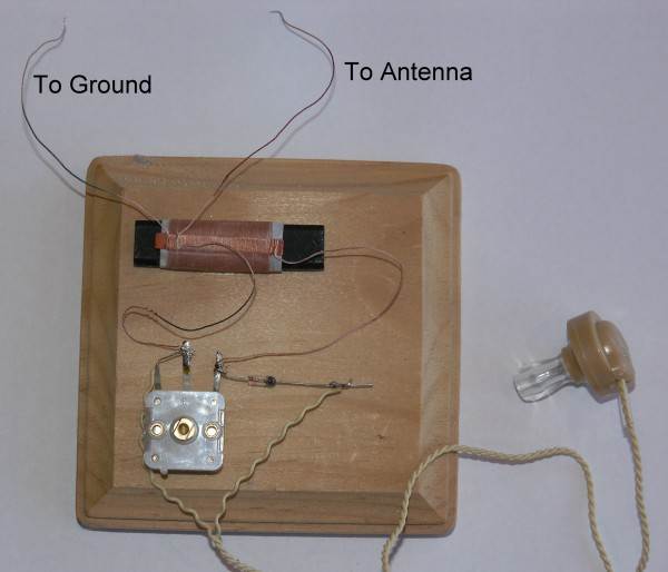
The crystal is connected to a thin sheet of aluminium and when it moves,
you can hear sounds such as voice and music.
The crystal has a very high resistance - about 10 meg ohms and you can
consider it to be an OPEN CIRCUIT.
But when a signal is delivered to the earpiece, the crystal appears to
be equal to a capacitor of about 20n.
This means the earpiece is just a like a 22n capacitor.
The signal picked up by the antenna and passed to the earpiece via the
diode will charge the "capacitor" and when the signal reduces, the
charge will remain on the "capacitor."
This means the aluminium diaphragm will move in one direction and there
is no component in the circuit to discharge the "capacitor" and move the
diaphragm in the opposite direction.
A 10k resistor is needed across the earpiece to discharge it ready for
the next cycle.
![]()
Here's a BLOWN FUSE circuit from
Professor Mohankumar.
When the fuse blows, the red and green LED will be delivering current
directly to the LOAD.
A LED can only withstand a small
voltage in the reverse direction and any voltage above this will damages
it.
When the fuse blows, either one or both LEDs will be damaged, depending
on the input voltage.
This is a USELESS circuit. It has not been tried or tested.
![]()
FIRE ALARM
Another badly designed circuit
from
Professor Mohankumar.
Here's two very clever names or words:
A trucking company by the name of: NEWAY
B
This is the worst circuit I have seen.
Someone on an electronics forum asked me how to measure the thickness of
wire.
SOLAR TRACKER
The designer of this circuit has used an op-amp that only "pulls-down"
(called an open-collector output). This means he has had to use a
pull-up 2k7 resistor.
Not a very good circuit because using two 12v batteries means having to
charge them separately if they are to remain connected to the
circuit.
BURGLAR ALARM
Here's another circuit from Professor Mohankumar.
NIGHT LAMP
The 33k will allow 7mA to flow, but since this is a half-wave circuit,
the average current will be 3.5mA. This will not produce a very
bright illumination.
LED REGULATOR
The output voltage is 1.8v - 0.6v = 1.2v NOT
1.6v
FUSE FAIL
Here is the description from
Professor Mohankumar:
The LED turns ON when the fuse blows. His description is
incorrect !!!!
POLARITY INDICATOR
Here is the description from
Professor Mohankumar:
When the positive and negative polarity of the power supply and
the load are correct, LED remains off. When the polarity of the load
reverses, LED turns on.
How can the polarity of a load reverse??????
Here is the description from
Professor Mohankumar:
A hobbyist has sent a technical question to Colin Mitchell.
Here's another useless circuit from
Professor Mohankumar.
Page 111
Page 2
Page 3
Page 4
Page 5
Page 6
Page 7
Page 8
Page 9
Resistor R1 is not needed. It does nothing.
The 5v1 zener can be removed as it simply changes the position of the
wiper on the pot.
You cannot get a 4k7 pot. It is 5k.
C1 does nothing.
You just need the 5k pot connected to the base of the transistor.
Adjust the pot until the buzzer produces a noise.
Adjust the pot to stop the noise and use a cigarette lighter to heat up
the NTC thermistor and see how much heat is required to produce a sound.
The sensitivity of the circuit will change when the battery voltage
reduces and it is only an experimental circuit and MUST not be used in a
real fire hazard situation. It has no beep to let you know the
battery is low.
![]()
A number plate: XINNY
Did you read them correctly: ANYWAY and
TINNY - referring to the original TIN LIZZY. The Ford
Model T (colloquially known as the Tin Lizzie, Tin Lizzy, T-Model Ford,
Model T, or T).![]()
Who is going to push the "BELL PUSH" for 2 - 3 seconds ???
The 12v circuit energises the relay to deliver 5v to the music chip.
You don't need the 7812 or the relay.
Who connects a "Bell Push" to the 240v - only someone who
wants to KILL their visitor !!!!!
This is the worst, most dangerous, unworkable, circuit I have seen.
DO NOT BUILD IT ![]()
All the replies said to use a micrometer - they really mean a
dial-micrometer.
But the cheapest and simplest way is to wind say 30 turns on a rod and
compare the length with 30 turns of the new wire.
No equipment needed - just INTELLIGENCE !!!!![]()
All component symbols - including diodes,
transistors, FETs and anything with an arrow, shows the way current will
flow in the device. This is LUCKY because it helps us remember and helps
us describe how a circuit works.
When drawing an electrical circuit or an electronic circuit, all arrows
refer to CONVENTIONAL CURRENT - this is the same as saying:
ELECTRICIAN'S CURRENT or ELECTRICAL CURRENT. Where "electricity"
flows out the positive terminal and into the negative terminal. We
also say CURRENT flows from positive to negative. We never say VOLTAGE
flows from positive to negative. Voltage is just the height of the water
and when the water flows in a pipe from a high point to a low point, the
flow is CURRENT. Voltage is just the pressure of the water that you can
feel at the outlet by putting your finger on the pipe and trying to stop
the flow of water.
If a lot of water comes out, the CURRENT is large.
Unfortunately, scientists (physicists) have found that electrons flow in
the opposite direction but EVERYONE who talks about the operation of an
electrical or electronic circuit, uses CONVENTIONAL CURRENT as the
direction of current-flow.
If you are talking about the atomic structure of a transistor and the
P-layers and N-layers and "channels" and "pinching effect" etc you
talk about ELECTRON FLOW or the movement of electrons; and the
flow of electrons is from Negative to Positive.
![]()
![]() .
.![]()
The correction is shown in red. The LEDs are used to receive
illumination
Why use an op-amp that does not pull both HIGH and LOW and save 2
resistors.
Connecting the collector of the first transistor in the super-alpha
arrangement to the collector of the output transistor means the output
transistor cannot turn ON fully.
If we take Q3, it cannot behave as an amplifier if the collector is not
at least 0.3v above the emitter.
If the collector voltage is less than 0.3v, the transistor simply acts
to pass the base current to the emitter via the natural voltage drop of
this junction.
With the collector 0.3v above the emitter, the minimum voltage on the
collector will be 0.3v plus 0.7v across the base-emitter of the TIP3055.
This means the collector of the TIP cannot go lower than 1v.
The solution is the connect the collector of the first transistor to the
12v supply via a resistor and this transistor can now provide the gain
needed to drive the output transistor.
The two super-alpha arrangements can be replaced by single Darlington
transistors such as BD679 (NPN) and BD680 (PNP). These arrangements will
deliver up to about 6-8 amps.
![]()
Firstly, what is the purpose of R5 ???? It can be removed.
R6 feeds a 5v1 zener.
When the output of the PIR sensor goes HIGH, R7 is placed across the
zener and this effectively puts two 470R across the 9v supply so about
4.5v will appear at their join.
At the same time a 1k resistor is effectively placed from the join to 0v
rail and this will reduce the voltage even further. The final voltage is
unknown but the maximum for the UM3561 is 3.6v.
Even though the circuit will work, the zener has already dropped out of
regulation and the voltage on the PIR detector has reduced and this may
upset its operation. It has an internal 5v regulator and the
voltage is already below this value. Not a very good way to design
a circuit. A zener should never be allowed to dropout of regulation and
the PIR sensor has an internal 5v regulator, so the 5v1 zener is not
needed.
![]()
Another badly designed circuit
from
Professor Mohankumar.
This is the original circuit.
The top 1N4007 is not needed because it does not do anything.
The 1N4007 across the LED is not needed because the top 1N4007
does not allow current to flow in the opposite direction and
the LED is protected from reverse voltage/current.
None of Mohan kumar circuits have been checked or tested.
![]()
Another bad circuit
from
Professor Mohankumar.
![]()
This circuit can be hooked between the power supply and the load.
When the fuse is intact, LED remains ON since it has continuity for
current path. When fuse blows, LED turns off.
The definition of a load is a device that does not produce or supply any
voltage or current.
How can the Indian student get anywhere with electronics when you have a
Professor spieling such nonsense.
CURRENT FLOW
This is ideal for battery chargers. If current is flowing to the
battery LED lights. It indicates whether the battery connector is
properly connected or not with the charger.
The voltage-drop across each diode is 0.7v. The total is 1.4v. A
LED requires a minimum of 1.7v. The LED will NEVER illuminate.
Another untried circuit.
From all these simple faults you can see Professor Mohankumar - an
Indian lecturer, has absolutely no idea about electronics and should not
be in charge of a class or put his RUBBISH on the web.
If I was a student and found out I was being taught rubbish from a
lecturer, I would be very ANNOYED.
![]()
He is using a CRO to determine the current in a LED flasher circuit.
He is using the x10 on the probe.
Here is his statement:
I see triangle wave, peak 5mV on the 10-times attenuated on the
probe - in reality it's 50mV.
The x10 position on the probe is only used when the voltage being
"looked at" is VERY HIGH - such as 500v or more.
The x10 setting or "position" on the probe is a slide switch that adds a
9M resistor and 1M resistor (in series) to the probe-tip so the 500v is
across 10M and this becomes a VOLTAGE DIVIDER where the CRO is across
the 1M resistor and thus it sees 10% of the actual voltage. Thus it sees
50v in this case.
The x10 position is not designed for 50mV viewing as the 50mV can be
viewed on the x1 position of the probe.
The x10 setting on the probe has another advantage.
The input to a CRO is about 1M. If you are measuring a voltage from a
flyback circuit or a capacitor multiplier, it will not be able to
deliver a high current and the circuit is said to be HIGH IMPEDANCE.
Suppose the impedance of the circuit is 1M.
When the circuit is producing say a voltage of 100v, the loading of the
CRO of 1M will reduce the voltage to 50v. But when the probe is switched
to x10, the loading will be only 10% and the reading will be 90v.
![]()
The current delivered by the 22k will be 240 / 22,000 = 11mA for each
half cycle.
This means the current available from the zener/electro section will be
11 / 2 = 6.5mA
The wattage dissipated by the 22k will be 240 x .0065 = 1.56 watts.
The 1 watt resistor will burn out !!!!
This means 6.5mA will flow through the 1k resistor and produce 6.5v
across it. The LED will produce 2v across it and the final output
voltage will be 8.5v.
At the moment all the current is flowing through the LED and the zener
is not in breakdown.
If you try to take any current from the circuit the output voltage will
drop.
Remember, you can only take a maximum of 6.5mA and when you take 6.5mA,
the output voltage will drop to ZERO.
Suppose you take about 1mA. This means the load will be 5k and the
voltage will drop from 8.5v to 6.7v.
What a useless circuit !!!!
![]()
Page 10
Page 11
Page 12
Page 13
Page 14
Page 15
Page 16
Page 17
Page 18
Page 19
Page 20
Page 21
Page 22
Page 23
Page 24
Page 26
Page 27
Page 28
Page 29
Page 30