SPOT
THE MISTAKES!
Page 31
Page 1
Page 2
Page 3
Page 4
Page 5
Page 6
Page 7
Page 8
Page 9 You have to be aware of what is happening in China.
I have added very little to this
Page 10
Page 11
Page 12
Page 13
Page 14
Page 15
Page 16
Page 17
Page 18
Page 19
Page 20
Page 21
Page 22
Page 23
Page 24
Page 25
Page 26
Page 27
Page 28
Page 29
Page 30
Page 32
Page 33
![]()
I have especially kept Talking Electronics website simple and easy to download.
All the other sites are filled with advertising and the articles are
cut-up between adverts, with the page taking a long time to load and
impossible to save. Most of them are not worth saving, in any case.
I don't care if I only get a few readers for some of the articles. It is
those few readers that will benefit from the discussion and, after all,
only one in 10,000 understand electronics. So it is a very exclusive club
that we are preaching to.
The main things is this: we are getting across technical material that
has never been covered before.
You can see the need for learning the "in's and out's" of electronics as
so many forums have technical personnel advising the reader with quite
bazaar solutions or a complex solution when a simple circuit is all that
is required.
And you can still see magazines producing projects that show the
design-engineer has little or no understanding of what is is presenting.
If only they had read the 30 pages of "Spot The Mistake" they would be
enormously better informed.
It's amazing. Not one text book has ever presented a faulty circuit and
explained the faults and how to fix them.
That's why, coming from a background of fixing 35,000 TV's, I could see
many design-problems and many ways to help others find and fix a fault
without having to spend hours looking in the wrong location. ![]()
They are releasing and using very low-cost microcontrollers that hardly
get a mention outside China and consequently the projects using them are
50% better than we can achieve.
PIC has release a Chinese-only version and STC has a very low cost
micro.
This signals the "beginning of the end."
We have already seen COB micros for 5 cents in 10 second speech and
sound modules and these have dominated the Birthday card market. But
no-one buys cards any more and I wonder where the next mass-market will
appear from.
The only thing the mass market are promoting is the smart use of generating
electricity and storing it within the home.
They are hoping battery storage will be come economical and provide the
independence we frantically need.
But when you consider a car battery will deliver 0.5kwhr, it will only
run a one-bar radiator for 30 minutes, these $5,000 Power-Walls are
really only a gimmick.
Who would pay $5,000 for $2.00 worth of electricity each day? Most homes
would need two Power-Walls to cover the nightly requirement.
You certainly could not turn on the tumble dryer and kettle at the same
time or do any worthwhile electric cooking.
However they are going to keep flogging these Power-wall batteries, just like solar
panels and create work for installers and servicemen.
So far, the introduction of solar panels on top of houses has made very little
impact on electricity requirements as all these households return to the
power-grid at nighttime. ![]()
Finally, my efforts to make authors desist, have sunken-in, and they have
stopped producing projects that don't work.
Of course they have never responded to my emails but the fact they have stopped
publishing projects without being tested, is sufficient testament to my success.
The reply from editors of the magazines with: "No-one
else has complained." does not wash with me. Of course no-one has
complained because my complaints are very technical and very few would be aware
of the mistake and even fewer would bother to write to the magazine.
From the replies I receive on various electronics forums I can see the general
understand of basic electronics is very low.
And I can understand why.
Where are they to get their knowledge from?
Universities don't have a clue.
Nothing is provided in any text books and there is no-where you can go to get a
sensible answer.
I am not talking about formulae and derivatives.
I am talking about how and why a circuit works or doesn't work.
Everyone relies on SIMULATION SOFTWARE and exactly the same software resides in
my head.
I can see a circuit working in exactly the same way as the simulation package
works. That means I don't have to draw the circuit or wait for an answer.
The software package will provide waveforms and timing diagrams but if you don't
understand the circuit thoroughly, these graphs will only create more confusion.
The same thing happens when you put a CRO on a project.
The waveform can include lots of glitches and spikes that are not registered by
the components in the circuit and this can cause additional confusion.
![]()
When I look back and see how many things I initiated and changed
and invented, the list is enormous.
I lived in the period of time when everything changed, from the valve era to
the transistor era to the integrated circuit era to the microcontroller era and
large-scale integration.
No only did the transistor radio get invented but the walkman, transistor TV's
and then the computer.
Finally we have the mobile phone, internet and microscopic electronic gadgets
for every requirement.
The small part I played in this dynamic change can still be felt by those
thousands of readers of my magazines and books.
I was the first to describe a circuit and include a section IF IT DOESN'T WORK.
All magazines expect the circuit to work and they never had a repair section or
any capability of sorting out the problem. This left the builder with a DUD
project and possibly put the builder OFF building anything more.
Talking Electronics had a repair section and a phone response.
And it was the first in the world to provide kits for
every project described in the magazine and put PC boards on the front of the magazine to encourage
constructors to build the project.
Not only that, but the PC boards had a overlay and tinned lands. The other
boards at the time had no overlay and just copper on the underside and no visual
indication of the name of the project. Sometimes letters such as "NHCD
234" or "OCT 1986"
It was no wonder that none of these junk projects were a success and yet the
magazines went on each month without any intention of providing anything better for the
beginner.
And it still holds today. Almost none of the magazines include a beginners
article and simply including a single article is very little reward for buying
the magazine.
I was the first to produce a magazine with no advertising. I am sick and tired
of flipping past all the advertising and finally getting to a few articles at
the end of the magazine.
I brought out my magazine just at the peak of the transition-time.
Things have now changed and the requirements for electronics engineers have
dwindled to such an extent that they have almost vanished.
Designs are now carried out around microcontrollers and large scale integrated
chips and multilayer boards with overseas engineers that are capable of
producing a product at a price that you cannot compete with.
You cannot buy a plastic box for the price of their completed project.
That's how much things have changed.
You see hundreds of new chips and components being developed but when you go to
the inventory of a large wholesale supplier you see the stock has changed very
little over a period of 18 months. The 47 items they have "got rid of" have
either been "free samples" or a "sample to try" and maybe a few sales.
I provided circuits each month to an Indian magazine and included my email
address in the article, plus the
cost of a kit. Not a single order or reply or request for information came to me
in a period of 18 months.
That's a 100% conclusion. The second largest magazine in India has a readership
(with electronics understanding)
of virtually ZERO.
When you go to their Forums, the questions and answers indicate everyone is
crying out for a little education in the electronics field. There is nothing,
anywhere, to help them.
It does not matter if a LIFETIME CAREER is not available for these enthusiasts.
It is more important to give them a hobby and an interest, just like the
enormous number who took up modeling (such as yachts, boats, scenery etc) and
model railways and wood-working.
It provides, peace, enjoyment, contentment and achievement.
It's a bit like the music industry. There is very little outlet for a musician
or singer, but millions are practicing 10 hours a day because of the love of
achievement.
It all revolves around gaining knowledge and achieving a goal. Achieving SUCCESS
and gaining IMPROVEMENT.
And this spurs you on to wanting to know more and knowing you are SUCCESS.
It's only internal success that you have to achieve. Once you have that, you can
impart your success to others (younger) and show how to maintain stability.
TO STAND FIRM WHEN ALL THE WORLD IS CRUMBING AROUND YOU.
![]()
Here's some poor and bad advice from an electronics forum:
Hi . . . I purchased a 12 volts 800mA, DC adapter and the output is 16.54 volts!
Answer from the technical supervisor:
The
resistance in the
windings of miles of thin wire in its transformer so its voltage drops
to its rating when it has its rated load current.
The supervisor is referring to the primary winding and this is
incorrect.
The thickness of the primary winding has very little impact on the
voltage-drop.
If the primary can maintain flux in the core when the maximum current is
being drawn, it is doing its job. And almost any thickness wire
will do this as the wattage is less than 15 watts in this case.
The voltage drop is due to the resistance of the secondary winding,
Just because a certain gauge wire in the secondary will carry 1 amp as a jumper lead,
does not mean it will deliver 1 amp as a secondary winding of a transformer,
without producing high losses.
To deliver 1 amp with low-loss, you need to use 5 amp wire but this will
take up a lot of space and you will need a larger core.
It is not the current-carrying capacity of the secondary winding but the
thickness of the wire and its ability to allow 1 amp to pass to the
output. It needs a much-thicker wire to deliver 1 amp. To prove the
issue, if you wind 2 turns of very thick "strapping" for the secondary,
it will produce 10 amps. The voltage will be less than 1 volt, but the
current will be 10 or more amps when you "short" the two ends together.
So the manufacturer uses thinner wire and winds 20% more turns, so the voltage is high
on no-load and drops to the specified voltage when full current flows.
"Try connecting a 470 Ohm (or thereabouts) resistor at the output and
measure the volts again. What do you get?"
This is another piece of useless advice from a non technical person.
A 470 ohm resistor will draw 30mA and the voltage will drop a few
millivolts.
You need to connect two 8 ohm resistors in series to get something like
700mA to test the transformer.
Using Bipolar Transistors As Switches by Mike Martell
While transistors have many uses, one of the less known uses by amateurs is the ability for bipolar transistors to turn things on and off. While there are limitations as to what we can switch on and off, transistor switches offer lower cost and substantial reliability over conventional mechanical relays. In this article, we will review the basic principles for transistor switches using common bipolar transistors.
The most commonly used transistor switch is the PNP variety shown in Figure 1. The secret to making a transistor switch work properly is to get the transistor in a saturation state. For this to happen we need to know the maximum load current for the device to be turned on and the minimum HFE of the transistor. For example, if we have a load that requires 100MA of current and a transistor with a minimum HFE of 100, we can then calculate the minimum base current required to saturate the transistor as follows:
Saying a PNP stage is "the most commonly used stage" is completely wrong because the voltage on the base has to be raised to nearly 12v to turn the transistor OFF and and many controlling circuits have an output voltage of 5v (such as microcontrollers) and you need extra circuitry to control this type of circuit.
HFE should be Hfe
100MA should be 100mA (100MA is one hundred MEGA AMPS - Such as from a power station - no transistor can control 100Mega Amps)
| Minimum base current =
100 MA / 100 Minimum base current = 1 MA Minimum collector current = 100 mA / 100 Minimum base current = 1 mA In actual practice, it is best to calculate about 30% more current than we will need to guarantee our transistor switch is always saturated. In this case, we will use 1.3 mA. We must also select our supply voltage, so for this example we will use 12 volts. We can now calculate resistor R1 in the circuit as follows: Maximum Current Required = 100mA Supply Voltage = 12 Volts |
 |
R1 = Supply Voltage / ( Maximum Current Required / Minimum HFE * 1.3 ) R1 = 12 / (.1 / 100 * 1.3) R1 = 9230.7 or 10K for nearest standard value. R1 = 9230.7 or 10k for nearest standard value. Resistor R2 is not essential to this circuit but is generally used for stability and to insure that the transistor switch is completely turned off. This resistor insures that the base of the transistor does not go slightly negative which would cause a very small amount of collector current to flow. The value of this resistor is not critical but a value about 10 times R1 is normally chosen. For this circuit we will calculate R2 to be 10 times R1 as follows: R2 = 10 * 10000 R2 = 100K R2 = 100k To turn ON our transistor switch, all that is needed is to short resistor R1 to the negative ground. I don't like the word "short." It should be "take." I don't like "negative ground" Just use the word "ground." It is the negative of the battery, but if you use the word "negative" it will conjure up the possibility that the supply is both positive and negative, like a dual power supply: +12v and -12v. PNP buffers (BUFFER STAGE - INVERTER AMPLIFIER STAGE - "SWITCH" ) are very difficult to get working because the incoming signal has to rise to 12v (in this example) and if it just rises to 11.5v, the circuit will not turn OFF. Even a 555 will not work in this example because the output of a 555 on a 12v supply will only rise to 11v. The driver circuit MUST be on the same rail as the BUFFER because if they are different by as little as 0.5v, the BUFFER will not turn OFF. |
|
While PNP transistors are normally used for a negative ground configuration, it is possible use a NPN What is a "negative ground configuration??" transistor if a positive ground configuration is desired as indicated in Figure 2. The calculation of resistor values is identical to the PNP version. However, in the NPN transistor, R1 must be shorted to the positive of the supply to turn the switch on. While our transistor switch can easily replace many mechanical relays, it does have a few drawbacks. The maximum design current must not be exceeded or the output voltage will be reduced. A short circuit of the output will overheat and destroy the transistor in many cases. Although the transistor is in saturation when turned on, about .3 volts is lost through the collector to the emitter of the transistor. We must also insure that the maximum power dissipation of the transistor is not exceeded. We can calculate the power dissipation by multiplying the current by .3 volts. In the case of 100 mA, the transistor must be able to withstand 30 milliwatts (.3 times .1). |
 |
| Transistor switches are used for a wide variety of applications. Many amateurs will notice that the circuit in Figure 1 is used as the PTT in many transmitter circuits. Transistor switches are commonly used to turn on transmitter circuits, LED�s, cooling fans and even relays. However, when using a transistor to turn on a relay coil, it is very important to use a 1N4001 diode reversed biased in parallel with the relay coil as in Figure 3. This is to prevent the kickback voltage in the reverse polarity from destroying the transistor. This reverse voltage occurs momentarily when the normal current stops flowing through the coil. It is good practice to always use a diode when turning on any inductive load. Transistor switches are often used to take the low-level output from logic circuits to turn on or turn off a particular device. |
 |
|
The actual transistor used as a switch is not critical in these applications. Virtually any general purpose NPN or PNP transistor can be used as a switch. All that is needed is to know the minimum HFE and the power dissipation of the transistor. While most transistors in a TO-92 case will have HFE�s of at least 100, many power transistors in TO-220 cases often have an HFE no greater than 25. It is essential to know the HFE or Beta of a transistor, so that we can have a large enough base current to achieve saturation. If a power transistor is used to turn on a high current device, it may be necessary to use another lower current transistor switch to drive a transistor switch used in a high current application. This is especially important when using a low current logic output from a CMOS IC. One of the biggest traps in designing a BUFFER stage occurs when driving or illuminating a globe. A globe takes about 6 times more current when starting to illuminate because the cold filament has a very low resistance. The resistance increases enormously when it is fully glowing. This means the current required to get the globe to illuminate is 6 times the operating current. This even applies to a 12v 100mA globe and if you only consider 100mA when selecting a transistor and the base resistance, the globe will not turn ON. And you will wonder why. Now you know. |
|
The author has gone to a lot of detail in how to work out the
value of each resistor. He states it is best to assume a transistor has a
gain of 50, and then states the circuit above has a very high gain. |
|
![]()

PCB power is an Indian company. I asked for a quotation on a Printed Circuit board panel and the cost was $120.00 plug freight. I had the panel made in China for $10.00 !!!
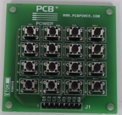
Here is a 4x4 Matrix kit supplied by PCB Power. The cost is $21.00 USD !! An Indian earns on a few dollars a day !!!!
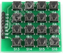
Here is the same 4x4 Matrix on eBay. It costs $1.00 (post free).
This is a typical example of the corruption produced when a government does
not allow the citizens to buy products from overseas. The manufacturers within a
country can exploit the population. All the electronics products produced in
India are very second-rate as hey do not have the resources, infrastructure,
know-how or the demand to produce items of a standard that is demanded today.
It is absurd that India and Russia produce items in competition with China
because they simply cannot compete and they are just making fools of themselves.
They are producing designs that we bought 10 years ago and are currently
throwing on the tip.
![]()
Page 1
Page 2
Page 3
Page 4
Page 5
Page 6
Page 7
Page 8
Page 9
Page 10
Page 11
Page 12
Page 13
Page 14
Page 15
Page 16
Page 17
Page 18
Page 19
Page 20
Page 21
Page 22
Page 23
Page 24
Page 25
Page 26
Page 27
Page 28
Page 29
Page 30
Page 32
Page 33