SPOT
THE MISTAKES!
Page 35
Page 1
Page 2
Page 3
Page 4
Page 5
Page 6
Page 7
Page 8
Page 9
Page 10
Page 11
Page 12
Page 13
Page 14
Page 15
Page 16
Page 17
Page 18
Page 19
Page 20
Page 21
Page 22
Page 23
Page 24
Page 25
Page 26
Page 27
Page 28
Page 29
Page 30
Page 31
Page 32
Page 33
Page 34
Page 36
![]()
These articles in SPOT THE MISTAKE are the most import discussions l
have produced because they teach electronics “IN REVERSE.” They teach how NOT to
design circuits and you can learn more in this direction than a 3 hour lecture.
That's the way I learned. Fixing 35,000 TV's. You get to know how to
design things properly.
I have recently proof-read a number books for beginners in electronics
and they are filled with mistakes.
All the mistakes located by other readers concentrated on incorrect lettering or
wording.
None of them picked up the overall lack of understanding of the author about
circuit diagram layout, selection of component values or descriptions of how the
circuit or components work.
“the current goes in the long lead of a photo-transistor” is one absurd
description (as all the leads are the same length).
And half a description of how a 555 lC works is no description at all.
A layout diagram is NOT a schematic. A layout diagram helps you wire up a
component on a prototype board.
A schematic enables you to instantly see what the circuit does and it needs
component values. They are entirely different.
There is not one schematic in any of his books. They are all layout
"up-side-down" drawings and l can't figure out how any of the
projects work.
If l can't, how do you expect a beginner to?
I have never cluttered a schematic with R1, R2 etc. . .. only component values.
And 470 for a resistor needs the designator: 470R.
Resistors should be rectangles and not zig zag lines. You can put the value
inside the rectangle to simplify the diagram.
The whole idea of a schematic is to produce a “picture” that can be analysed
instantly.
I can look through a book of 1,200 circuits and determine what each circuit
does, instantly.
Everything in the books we are discussing, can be found on PINTEREST website. You will find hundreds of books and projects and you have to be careful if the project works or not. Nothing is tested.
https://au.pinterest.com/search/pins/?q=electronics.books
![]()
MAKE BOOKS
There are a number of books from the enterprise known as MAKE, written by the
author: Charles Platt.
On the surface, these books look to be well presented, with thick pages and
glossy photographs of so many things.
I had previously glanced though one of these publications and noted a number of
mistakes, but did not take the matter any further.
However the author contacted my by email one day and I mentioned the fact that a
book had a number of mistakes.
He seemed enthusiastic and wanted me to send him the mistakes I had found.
After a few more emails he continued to accept the corrections and then
sent an email:
"I'm blocking you now."
Why am l critical of the books
published by Make?
Because I did not get an answer from the author, or the publisher, as you will
find out later.
I am critical because the books do not provide a real understanding of electronics.
Not only do they contain a lot of mistakes but they do not follow the accepted
way to show a schematic.
If you look at all the books of schematics, they show the connections to
Integrated Circuits in a particular way so the viewer can instantly recognise
the chip.
LAYOUT DIAGRAMS
In the Make publications, the diagrams are LAYOUT diagrams to help the
constructor place the jumpers on a breadboard.
This is perfectly fine, but it is not educating the constructor in electronics.
The book costs about $30 and for this money l would expect it to teach
the subject.
At the end of the day, l gained nothing from the book or the experiments.
Some were extremely complex with lots of logic gates. TTL IC's
I have to say this type IC went out 30 years ago and was replaced with
tiny 8 pin microcontrollers.
That was one of the reasons micros became so popular. 8 TTL chips cost more than a
single micro and the board is one tenth the size.
The concept of using lots of gates has “gone out the window, years ago” and a book like
this is “flogging a dead horse.”
If the circuits had been in schematic-form, the constructor may have learned
something, but when they are a jumble of wires and jumpers on a breadboard, the
whole exercise: “falls flat.”
But that’s the problem with so many of the YouTube projects. They are either
badly designed, faulty or don’t teach anything electronic.
And the end result is a mass of constructors that are not really learning the
basics of electronics.
It’s “the blind leading the blind.” The authors are not sufficiently versed in
electronics to present a quality project and none of them know enough to be able
to describe its operation.
And that’s why we have a whole generation of constructors with a smattering of
knowledge.
Fortunately a lot of them have taken on programming microcontrollers, where just
a little knowledge of electronics is enough to get a project working.
I cannot imagine why a writer would put layout diagrams in a book that is
supposed to be for beginners and supposed to be educational.
When you look at the layout diagrams in the book, l would not be able to describe
any of them because a circuit diagram has every component in a particular location
and the gates are placed individually on the diagram so you can see what they are
doing.
Another stupidity of Layout Diagrams is this: You cannot compare one schematic
to another.
All the projects in the book are worthless. Not only because they use old TTL
technology but nothing is explained about the operation of the circuit or how to
test it.
Then we come to discussions on YouTube from contributors who have looked at the
cost of the kit for the book. They all say it is enormously overpriced. Some say the pins on
the relay are too short and others say the parts have a different pin-out.
Not one reader has said he has built any of the projects and not one has said he
had learnt anything from the book. That’s a clear acknowledgement of what l am
saying.
The whole package is overpriced and delivers nothing.
REPLY FROM CHARLES PLATT
The reply from Charles Platt, Make Publications and ….. ware Publications has
been absolute ZERO.
I never expected a reply because the errors and comments l made were so damaging
that they could do nothing but “shut the door.” All they said was “the
discussion is over,” “l am deleting you” and silence.
Never had they met a comment that was more than change a component value or add
a component to the list.
Never had they met a person capable of looking at the overall failures in the
book and commenting on the circuit diagrams, the false statements, the use of
“pre-historic TTL chips” and never mentioned the fundamental concept of circuit
design: BUILDING BLOCKS.
On top of this, no mention is made of the fact that all circuits are designed
around a phenomena called: THE VOLTAGE DIVIDER.
A little bit of recognition would be a wonderful thing, considering they are
being shown things that will improve their standing in the educational field.
It’s all fun to present big colourful pictures of projects but if Tandy had
produced its 100 in 1 set of projects with layout diagrams, l would have learned
NOTHING.
Even after 50 years, l cannot read a layout diagram. It means nothing to me.
It’s just a jumble.
And that’s why the young enthusiast is getting no-where.
He is building things and poking wires into breadboards without an
understanding.
No-where is there even the slightest mention of how the circuit works or how to
test it or fix it.
If you expect a beginner to poke a hundred wires into a breadboard without a
mistake, you are fooling yourself.
I would not waste time with a 6 chip project. Without a schematic, the whole
endeavour is worthless.
And l would not waste $60.00 to $100.00 or more on a set of components that can
be bought on-line for $20.00.
The book is a piece of Junk. When does something become JUNK? When it does not
perform the task it was purchased for.
The requirement of this book is to teach electronics. To educated the beginner.
It is not a text book "of engineering." It is a set of projects for the beginner.
And how this education is passed to the beginner is unknown by the beginner.
He does not know what is to be learned.
You can “feed him anything” and he will “suck it in.”
And that’s where the book “falls down.”
I happen to know how to teach and what to teach.
I learned from my years at university. I came out understanding NOTHING.
I had to start by teaching myself. The instructors taught me nothing. I hadn’t
even handled a transistor!
And this book is just a repeat of this. The transfer of electronics
understanding from this book is seriously lacking. The main feature of
understanding schematics is absent.
And without this, the projects provide NOTHING.
WHY AM I SO ABRASIVE?
I have taken it upon myself to expose all
these worthless books and videos and lectures from Universities since the day I
was scammed by Mimms III with his "Book 2" on electronics. I bought book l and
was waiting for book 2. I had to get my cousin in the US to send me a copy
at enormous expense and when I got it, I found it was just a re-gurgitation of
Book 1.
This "got my back up" and I vowed to never CON anyone with the same scam.
I used Mimms grid layout to write many of my books and he was upset with my
"thievery."
However it was a huge success.
After that I proof-read many books and sent them to the publisher. They were
never re-printed.
Proof-reading is not just a blind reading of the text, but an analysis of what
the author is delivering but also delivering improvements.
That's why a proof-reader has to be competent in the field being analysed so the
publication is adding to the knowledge of the reader.
That has obviously not been the case with the MAKE set of books.
And that's why I have produced these pages of mistakes.
Not for the benefit of MAKE, but for the benefit of the reader, who has been
over-charged for works that are simply copies of data that can be easily accessed
on the web, via Google.
Platt asked me why I didn't write my own encyclopaedia. I didn't because it is
already on the web. I don't COPY and PASTE things. I produce new
information that has never been written before.
FREE
Everything is FREE on the internet and you certainly do not have to pay $30 for
a book filled with errors, mistakes and junk content.
In 50 years l have never had a technical representative at a publishing house
respond with an email that says he is finished communicating with me and “don’t
waste our time.”
This is the sort ignorance l have received in the past 50 years from Americans
who think the “sun shines out of their arse.”
In fact the understanding of electronics in the US field is very poor - almost
non-existent.
In 50 years l have not had a single competent technical reply from an American.
Some of the things they write makes you wonder where their understanding comes
from.
Maybe from university. Because University YouTubes are embarrassing.
Not one YouTube covers a topic in a practical way.
They all introduce mathematics and expressions that l have never used in my life
and would produce completely erroneous results.
You have no idea how a circuit (stage) will perform without full details of the
input signal and the load on the output. And an input signal does not come from
a “signal generator.”
In Australia, a technical writer for Electronics Australia made a simple
mistake about charging a battery and his 20 years of technical writing was
finished.
Junk, like in these MAKE books would not get “the light of day.”
Saying “a fuse is made from nichrome wire” and a white LED requires 2v, is
simply an unforgettable mistake.
And then to leave these faults in subsequent printings for 12 years, shows the
ignorance of the readers.
If the writer had any capability at all, he would have designed Printed Circuit
Boards with hollow pins on each land and IC sockets on the board so the beginner
could fit the leads of the components down the pins and create a PCB module
without any soldering required.
But this is way beyond the thinking and intelligence of the writer and he has
finished up with a crowded breadboard that delivers no benefit to the beginner.
I would not build a complex, junk circuit on breadboard, so why do you expect a
beginner to do it? What does he learn? There is not even a schematic in
the book!!!
That's the intelligence level of Americans. No wonder they voted for TRUMP!
MORE ON CIRCUIT LAYOUTS
There are so many faults in Make more electronics book, but one of the
biggest faults is the way the circuits are laid out.
All circuits work on a feature called VOLTAGE DIVISION. (Voltage-Divider).
This means the voltage
across each component depends on its resistance.
To make it easy to see how this
applies to each of the components, we draw the positive rail at the top and the
0v rail at the bottom.
Now, when we have two components in series, we can see the top component will
have a certain voltage across it and the bottom component will have a voltage
across it.
The voltage across each component may be the same but we say the top component
is “sitting higher” as it will have full rail voltage on the top lead and mid
rail voltage on the other lead.
This is clear and obvious when the power rails are at the top and bottom of the
circuit.
In this book, the rails are on the left and right and this VOLTAGE DIVIDER
principle is not obvious.
That’s why this book is such a bad instruction manual.
On top of this, the other components are so badly placed, and the wording is so
inaccurate, that the reader is “sidelined” from reality.
It is worse than not providing anything at all.
Here are a number of other things I do not agree with:
The author does not like: 3k3 or 4k7, but 3.3k and 4.7k. And he says the pins of
an IC are “leads.”
He has never heard of “e-z clips” or “jumper leads” and uses breadboards with a
single power rail on each side. These breadboards have “gone out with the ark”
He has never mentioned the flat spot on the side of a LED or understands a
“trimmer” is not the name for a “trim-pot.”
In his discussion on soldering, he does not mention SOLDER-TIP PASTE.
This is not solder-paste for surface mount components.
Here is a picture of of the $3.00 paste and the junk 60/40 Chinese solder.


Just dip the hot tip into the paste very quickly and the tip is cleaned of all
impurities and makes a much quicker, cleaner joint. When you use it, you will
EVERY go back.
Obviously the author has never used this product..
And here's another observation:
No author has said he has had any problem of Chinese
solder.
All the Chinese solder is RUBBISH.
It does not melt. It does not stick and the parts fall off.
To use up the junk Chinese solder you have to twist a meter of the junk with
good 60/40 solder (with an electric drill) and they two will combine to make a
good joint, when you use them together.
The junk Chinese solder does not contain enough tin (as it is much more expensive
than lead).
THINKING: "OUTSIDE THE BOX"
You have to “think outside the box” to explain why MAKE books are so
uninformative.
You have to look at how l have presented my hundreds of projects.
The first item in a project is a schematic of the circuit. Not a layout and not
a photo.
With a schematic l know exactly what the project does and l can continue or
“move on.”
MAKE projects don’t do this. I have to “look and search and wonder, and turn the
page around” to work out what the
project is doing.
That’s why the American electronics industry is so lacking in education.
All the American hobbyist electronics magazines have folded. Even when they had 3 in the
market-place, the sales were extremely small for such a large country. None of
them provided a back-up with kits or boards for any of the projects and Radio
Shack was just a junk store with odd components. The only supplier with quality
kits was HEATH-KIT but the prices were too high for the beginner. The few
electronics parts stores were miles apart and all went bankrupt, years ago.
The only thing that helped the beginner was Tandy’s 30-in-1 or 100-in-1 box of
projects with jumper wires and breadboard.
These projects showed the schematic and the layout of parts on the board and
were the backbone to teaching electronics in the ‘50’s to ‘90’s.
l had one young enthusiast wanting to work for me with his audio amplifiers and
gold detectors and he was able to draw the circuit without any references. I
hired him immediately
A circuit is a “picture.”
I can look through a book of 1,200 circuits and instantly see how they work and
pick the circuit or part of the circuit l need.
All circuits consist of BUILDING BLOCKS and you can combine these to produce or
design a completely different project.
This saves you: “reinventing the wheel.”
None of these techniques are covered in any MAKE publications because the
writers have no understanding of these techniques.
It’s “the blind leading the blind.”
And that’s the sad part of the electronics education system.
All the knowledgeable instructors have retired and newcomers have no access to
educational kits at affordable prices.
MY EMAILING PROBLEMS
There
are far too many email address for the author, the publisher, the kit supplier,
the errata, the other publisher and still more.
The author contacted me and l said there were lots of mistakes in the book and
he wanted a list. I provided a list and got no reply.
For the list of 15 mistakes he could have replied and thanked me for the
corrections but these people are so arrogant and think they are perfect. Just
because no-one has discovered the mistakes in 12 years does not make them
irrelevant.
To make sure the mistakes were sent to the publishers, l also contacted them.
They said the list has to be sent to their errata email. The errata address only
accepts text! My list included images. That’s how primitive the publishers are.
Not one complainant has been able to send a fault with a diagram.
Then they said a different publisher had taken over the publication and l had to
start all over again.
To the second publisher l sent the errata and a description of the piezo
diaphragm and the piezo buzzer and mechanical buzzer. The reply from
Jim Gleaves
their Technical Support person was:
Piezo devices are fully discussed in Encyclopaedia of Electronic Components,
volume 2.
stop wasting people's time.
Jim
Jim Gleaves | Technical Support
O'Reilly Media, Inc. | Contact Us
This is the sort of
"wonderful reaction" l have received from American publishers over the
past 50 years.
They think they rule the world. They have the attitude of TRUMP.
Overall US books are very poor. They all miss the point of actual instruction,
actual EDUCATION and covering the most important part: HOW THE CIRCUIT WORKS.
I have proof-read many books before the second publication and found enormous
mistakes.
Not one book was re-published.
It’s not just the mistakes but looking at the projects and
seeing they could have been done simpler and better.
And that’s the overall problem with the experiments in this book.
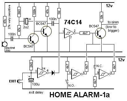
The author has not heard of the 74c14 CMOS hex Schmitt trigger IC.
It has six individual Schmitt trigger inverters that can perform amazing feats
with a few surrounding components.
I have used one in an alarm circuit and when you see the schematic, you can see
exactly how each section works.
This alarm detects sounds in the room and has 3 or 4 piezo sirens to
completely overpower the intruders hearing so he does not know if he has been
detected and leaves.
That’s what teaching is all about. GETTING SOMETHING ACROSS.
And that’s where the book: “falls down flat.” It’s just a jumble.
Sticking jumpers into a breadboard is not learning electronics.
Teaching electronics is no different to teaching someone to recognise a picture.
The picture is a circuit. A CIRCUIT DIAGRAM. A SCHEMATIC. And every component
must be placed in a certain position on the schematic to perform the required
task and to show its task.
And all circuits consist of BUILDING BLOCKS. That’s all l know. That’s all l
have to know.
A huge, complex circuit consists of individual Building Blocks and that’s why it
is so easy to learn. You just have to understand how individual building blocks
work and then see how they are connected together.
Connecting things is called INTERFACING when connecting a device such as a
switch, microphone, relay, speaker etc.
Or COMBINING when connecting one BLOCK to the next. Blocks are generally
connected with a wire. . . Called direct or DC connection, with a capacitor. . .
called AC connection or maybe an opto-coupler or transformer.
That’s why you can create a completely new project by taking previously-designed
blocks and connecting them together.
These are all concepts that have never been covered in any text book or project
book.
That's why I cover them on my website.
And that's why I get emails from readers of my magazine, saying they learned
more from my articles than their University course.
BUILDING
BLOCKS
Yes. I am particularly annoyed at most of the
publications, books and YouTube videos as well as lectures from universities.
Almost all of them are covering the topic incorrectly. I can see it, because l
have been designing circuits for 50 years and never used any of their methods or
computations. Circuits are not designed with mathematics.
The biggest mistakes revolve around simple transistor circuits.
Not one lecture has explained how a transistor circuit works.
You can see this by the component values they use.
The use an input signal that comes from a signal-generator, it has much more
“strength” than reality and the use an output load that l have never experienced.
The biasing of the transistor is going to severely attenuate the input signal
and the output needs to match the impedance of the following stage to get good
signal transfer.
You might think you can do this with mathematics, but none of the impedance and
resistance values are really known.
All these change according to the frequency of the signal and signals are not
only complex but you need to hear the result and decide if the bass or treble
needs to be attenuated or lifted.
You will have to change some of the components, so all your mathematical
calculations have been for nothing.
Why waste your time in the first place?
Why not talk about how they circuit works and say that for a self-biased common
emitter stage, the gain will be about 70.
Then, all you have to do is set the collector current at between 0.1mA and 1mA
and use a base bias resistor to get mid-rail voltage.
You just need a $10.00 multimeter to do this.
Start with 22n to 100n for the input capacitor and 1u to 10u for the output.
Nothing else is needed.
The circuit is self-biasing and the signal is so clear that you think the person
is in the room. That’s the easy part.
You need to interface (connect) the stage to an input device and the next stage.
This is where some knowledge is needed.
We classify the input of our stage as MEDIUM. This means it is not HIGH and not
LOW.
But l am not going to give it any value because the value will change enormously
with the frequency of the signal.
And secondly, there will be a lot of attenuation in the signal, no matter what
we do.
The amount of attenuation (signal loss) will depend on the strength of the
signal and the strength is determined by the value of the load resistor of the
device delivering the signal.
I will give you one simply example.
If the load resistor of the input device is 10k, and the input of our transistor stage is 5k, these
two values will produce a voltage divider of 25%. And that the maximum you will
get into the stage.
EASY ELECTRONICS
Charles Platt has also produced a book called: EASY ELECTRONICS.
ln it he constantly refers to an AA cell as a “battery.”
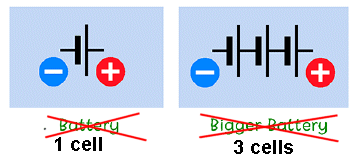
You have to keep to convention. A battery is a number of cells.
How this simple fact was missed the proof-readers is beyond me.
Another major mistake in the book is in the diagrams. It is normal convention to
put the load in the POSITIVE LINE. This means the negative rail, the 0v rail is
drawn across the bottom of the circuit from the battery to the lower lead of the
load. A switch is inserted in the positive lead and the top of the load.
This is CONVENTION. This is the way it is done.
Every book abides by this convention so circuits can be easily understood.
You certainly don’t deliver anything else to a beginner.
This book should be withdrawn.
Another major mistake is also in the diagrams.
It is convention to place the load in the “collector circuit.” . . . . the
collector lead, so the emitter is connected to the 0v rail.
![]()
Incorrect layout
Incorrect layout
The correct circuit to
test a transistor
This is called COMMON EMITTER design and is the arrangement l have used for the
past 50 years. I have never used the arrangement shown in the book, which is
EMITTER FOLLOWER or COMMON COLLECTOR.
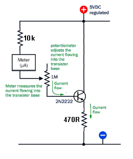
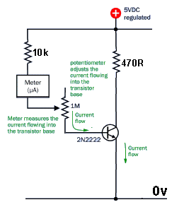
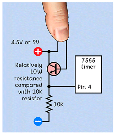
Experiment 10. The 7555 lC does not see any negative voltage on pin 4 from the 10k
resistor.
CRITICAL WHISTLEBLOWER
THE INDUCTOR
Here is typical example of the type of mistake and the lack of description of
HOW THE CIRCUIT WORKS.
Figure 5-33.
In this demonstration of self-inductance, D1 and D2 are light-emitting diodes. When the switch is closed, D1 flashes briefly because the coil obstructs the initial flow of electricity. When the switch is opened, D2 flashes as the collapsing magnetic field induced by the coil releases another short burst of current.
Compare the two lines of description above with the following:
The effect is this:
The reverse voltage or opposing voltage produced by the expanding flux is
initially 99% because there must be some forward voltage to produce the flux. It
takes energy to produce the flux and as the flux increases, the energy required
becomes greater. That’s why the expanding flux does not produce as much opposing
voltage as the time increases.
However there is a LED across the coil and it has a characteristic voltage,
depending on the colour, that is between 1.7v and 3.2v that appears across it
when it is illuminated and this voltage never rises above this value.
The overall content of the books is
what i will be concentrating on. .
Page 11
Page 2
Page 3
Page 4
Page 5
Page 6
Page 7
Page 8
Page 9
There are a lot of technical reasons why the Common Emitter arrangement is used
and you can find out the reasons in THE TRANSISTOR AMPLIFIER article.
The arrangement he has used teaches the beginner nothing because it is never
used.
If we have a circuit with a battery, resistor and globe, the convention is to
place the resistor above the globe as it will have full rail voltage on the top
lead and the globe will have 0v on its bottom lead.
This allows the VOLTAGE DIVIDER concept to be understood. This is the concept of
actually TEACHING ELECTRICAL or Electronic theory.
The author does not have the pleasure of creating his own terminology.
Experiment 5 will work with a LED but not a transistor. That’s because an
Emitter Follower circuit cannot be used to deliver high currents. The reason is
complex and is covered on my website. Just another complete failing from the
writer.
The author has omitted a current limiting resistor on pin 3 of the 7555. This
might be ok for 4.5v but the beginner may think a resistor is NEVER needed.
This is not a “Spot The Mistake” book. It is supposed to be a teaching book.
A LED does not have a “+” and “-“ lead. It is technically identified by the
cathode lead “k” and this is either the shorter lead or the lead next to a
flat-spot on the side of the LED.
This is an understanding known by all technically literate writers, engineers,
lecturers, professors and students.
And anyone not following this convention and understanding, needs an education.
I don’t know where the author got the breadboard without a positive and negative
bus (down the sides), from. But maybe you can find one in a museum.
Pin 4 of a 7555 is a high-impedance pin and can have a 100k to 1M so the photo
transistor can pull the pin down to less than 0.5v, to activate the chip, with
the slightest amount of light. With 10k you need high illumination. Using a 10k
resistor shows a complete lack of understanding how a photo transistor works.
Overall the book gets an “F” . . . for frighteningly awful. One of the worst
publications l have proof-read in my life.
How it got past the technical staff, proof-readers, editors, coffee-boy-staff,
teachers, professors, book-pirates, hundreds of “testers” and thousands of
readers, is beyond me.
Experiment 10 The letters on the transistor should be labelled cbe to let the beginner
know, as the transistor can have two different identifications. (from two
different types and/or from different manufacturers. . . . . it’s just a
jumble).
The same for the photo-transistor. It should be labelled c and e.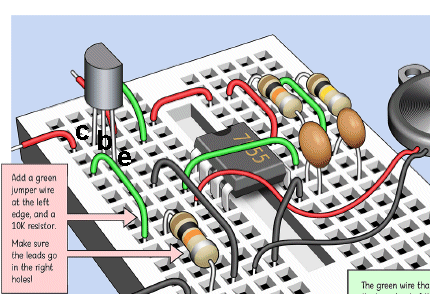
![]()
The voltage divider on pin 4 creates a voltage on pin 4 that needs to be less
than about 0.5v for the lC to detect a low and this “turns the chip off.” Any
voltage above about 0.6v allows the IC to operate.
That’s why you should never label a circuit with + and - but rather “rail
voltage” and 0v.
Otherwise l am confused and don’t understand anything.
Charles Platt has a website: www.plattelectronics.com where he says you will
find additional helpful information.
I went to the site and found links to random suppliers of kits and parts with
nothing to do with the book or any help at all.
I am critical of all these authors and university courses because they do
NOT teach “practically anything“ that is beneficial, accurate or applicable to
understanding the basics of electronics.
I learned from my own experience where I completed a 3 year electronics course
some 60 years ago and applied for my first job and was accepted immediately.
To my horror, l could not perform any of the tasks AT ALL. I had no idea
what to do. I had been taught absolutely NOTHING.
Fortunately the boss did not say anything and l learned very quickly.
But when l went back to the University with a TV repair problem, the instructor
said "he was not here to fix my TV."
I never returned to University.
And that’s why l am so critical of these books and YouTube videos and University
lectures.
They are completely “off the mark”
They tie up the student with mathematics that is completely irrelevant and
unnecessary.
What should be taught is an overall understanding of how the circuit works, how
each component determines the operation and function of the circuit and how to find and fix
it, if a fault occurs.
I have never used mathematics in my life as it does not work. Component values
can have wide tolerances and then, to see an answer to two decimal places (1%
accuracy) with 20% capacitors, is absurd.
There has to be whistleblowers like me as 99.9% of electronics hobbyists don’t
understand any of the mistakes in the book and the other 10% don’t care.
Thousands of hopeful electronics students go to University and spend up to
$70,000 on a course that will teach them nothing and give them no possibility of
employment.
The percentage of students completing a course and finding work in the chosen
profession, is less and 25%. The rest find work delivering parcels and cleaning
shops at 3AM.
So, whatever you learn, it must be factual and beneficial.
And the only way to learn is to teach yourself.
If you think a school is going to teach you anything, you are mistaken.
Where did the teacher get his understanding from?
It’s the “blind leading the blind.”
The old saying is: “lf you can . do . . . if you can't . . . teach.”
The input to learning electronics is 99% your own effort.
I have not found one single article or lesson or text-book or University course
that covers the absolute essentials of understanding how circuits work.
They don’t even teach soldering.
Show me one course that covers the two ways to solder.
One is to have the iron at the specified temperature and solder slowly. The
other is to have the iron at a much higher temperature and solder very quickly.
You would think the high temperature would destroy the component but it cleans
the joint very quickly and the time taken is reduced and the component does not
overheat.
Courses are expensive enough without someone coming along with a book filled
with mistakes and presentations that will make you look stupid, if repeated.
Not only that but the book teaches you almost nothing.
No schematics or description of how the circuit works. And there were book after
book like that from TAB books and other authors that just ruined the market.
Electronics is a visual subject. Something that has never been explained.
It starts with a circuit diagram. Every component must be placed on a diagram in
a particular location and then its value is taken into consideration as to what
it does.
Each component has a symbol and it does not sit dormant on a schematic.
Capacitors and electrolytics charge and discharge and the resistors and leads of
integrated circuits, connected to these components, rise and fall.
The output of gates rise and fall and everything is “moving up and down.” That
how l see a circuit and that how the inventors of CAD packages see a circuit and
produced Circuit Simulation packages.
I have never used one of these packages in my life because l can see the circuit
“moving.”
And that what’s you have to be able to do, to understand electronics.
This circuit is one of the most important features to explain how an inductor
works.
If you don't explain it fully, it is just a waste of a page in the book.
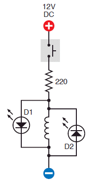
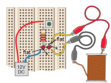
The most important part to identify the cathode lead (k) of a LED.
It
is beside the flat spot on the side of the LED (the shorter lead)
When the switch is pressed, one LED flashes. When the switch is released, the
other LED flashes.
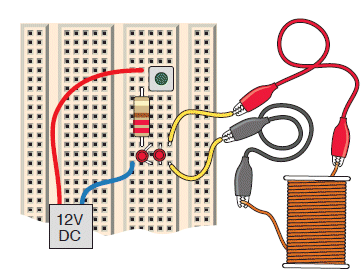
The circuit consists of 4 or 5 components and should be easy to describe.
But it is very complex and needs a lot of description.
It is the simplest circuit that demonstrates the effect of a COIL - called an
INDUCTOR.
There are two components in this circuit that need to be described in detail.
The inductor (the coil) and the LED.
When a voltage is applied to the terminals of an inductor, current enters the
inductor and produces magnetic flux from each turn. This flux is called
increasing or expanding flux and it cuts or “passes through” all the other turns
and in doing so it produces a voltage in each turn that is opposite to the
applied voltage from the supply.
This means the voltage entering the coil is opposed by a voltage as high as 99%
from the voltage developed by the turns.
This means only a very small effective voltage is present and this produces a
very small amount of flux.
That’s why the forward voltage gradually increase and so does the current.
Eventually the magnetic flux becomes a maximum and the supply cannot deliver
a higher current.
At this point the voltage across the inductor is equal to the supply voltage and
the flux is a maximum and is not expanding - but has a constant value. The
inductor is now classified as an Electromagnet.
The circuit remains in this state.
NOTE:
The only reason this effect is occurring is due to the flux expanding or
increasing. If the flux stops expanding, the induced voltage drops to zero.
So we have the situation where the voltage across the inductor is never more
than say 1.7v and the inductor produces a back voltage of 1.69v in the
beginning. This mean the LED sees a voltage sufficient for it to illuminate. And
that’s what happens.
When the power is applied, the LED illuminates. Gradually the effectiveness of
the expanding flux does not produce the same back voltage and the voltage across
the inductor reduces. As soon as it falls to 1.6v, the LED will not stay
illuminated and it goes out. The inductor now turns into an electromagnet with
maximum flux that is not expanding. The circuit stays in this state.
When the switch is opened, the current stops flowing and the magnetic flux
collapses. This collapse is very rapid and it produces a voltage across the
terminals of the inductor that is reverse to the previous voltage. If the second
LED was not present, this voltage would be very high and could be 10 times to
100 times larger.
But the second LED also has a characteristic voltage that prevents the voltage
across it rising above say 1.7v and when the voltage reaches this level, the LED
illuminates.
The collapsing magnetic flux delivers its voltage and current to the LED to
produce a bright flash.
Amazingly, the coil would have produced a high voltage and very small current,
without the LED. This is called ENERGY. The LED converts this ENERGY into a low
voltage and high current. That’s why the flash is so bright.
This simple circuit needs an enormous amount of understanding and a few simple,
vague, sentences will explain nothing.
The secret behind understanding this circuit is the fact that the inductor
produces a voltage in the opposite direction when the switch is opened.
We have one more important feature to discuss. The inductor is in series with a
resistor.
We have said the inductor produces an opposing voltage when voltage is first
applied and the current is very small. When a very small current flows through a
resistor only a very small “voltage drop” is created across it.
This means the full supply voltage is delivered to the inductor. As the opposing
voltage produced by the inductor decreases, the current increases and the
voltage drop across the resistor increases. This reduces the magnetism the
inductor is producing however the effect still continues and in the end the
inductor produces no “back voltage” and now the resistance of the winding in
“Ohms” is what the circuit sees. It sees two resistors in series and they become
VOLTAGE DIVIDERS. The resistor is 220 ohms and the inductor may be 10 ohms. This
will determine how much current flows and it will determine how much magnetic
flux is produced by the electromagnet. Obviously it will be much less than
connecting the inductor to the supply.
There are two components in this circuit that need to be described in detail.
The inductor (the coil) and the LED.
When a voltage is applied to the terminals of an inductor, current enters the
inductor and produces magnetic flux from each turn. This flux is called
increasing or expanding flux and it cuts or “passes through” all the other turns
and in doing so it produces a voltage in each turn that is opposite to the
applied voltage from the supply.
This means the voltage entering the coil is opposed by a voltage as high as 99%
from the voltage developed by the turns.
This means only a very small effective voltage is present and this produces a
very small amount of flux.
This only reason this effect is occurring is due to the flux expanding or
increasing. If the flux stops expanding, the induced voltage stops also.
So we have a microscopic instant in time when the expanding flux is not as fast
and not as powerful and the opposing voltage is only 98%. This allows slightly
more current to enter the coil.
This effect continues until the voltage produced by the inductor is zero and the
supply produces magnetic flux in the coil that is a maximum and full supply
voltage appears across the coil.
The inductor is now called an ELECTROMAGNET.
However there is a LED across the coil and it has a characteristic voltage,
depending on the colour, that is between 1.7v and 3.2v that appears across it
when it is illuminated and this voltage never rises above this value.
So we have the situation where the voltage across the inductor is never more
than say 1.7v and the inductor produces a back voltage of 1.69v in the
beginning. This mean the LED sees a voltage sufficient for it to illuminate. And
that’s what happens.
When the power is applied, the LED illuminates. Gradually the effectiveness of
the expanding flux does not produce the same back voltage and the voltage across
the inductor reduces. As soon as it falls to 1.5v, the LED will not stay
illuminated and it goes out. The inductor now turns into an electromagnet with
maximin flux that is not expanding. The circuit stays in this state.
When the switch is opened, the current stops flowing and the magnetic flux
collapses. This collapse is very rapid and it produces a voltage across the
terminals of the inductor that is reverse to the previous voltage. If the second
LED was not present, this voltage would be very high and could be 10 times to
100 times larger.
But the second LED also has a characteristic voltage that prevents the voltage
across it rising above say 1.7v and when the voltage reaches this lever, the LED
illuminates.
The collapsing magnetic flux delivers its voltage and current to the LED to
produce a bright flash.
Amazingly, the coil would have produced a high voltage and very small current,
without the LED. This is called ENERGY. The LED converts this ENERGY into a low
voltage and high current. That’s why the flash is so bright.
This simple circuit needs an enormous amount of understanding and a few simple,
vague, sentences will explain nothing.
The secret behind understanding this circuit is the fact that the inductor
produces a voltage in the opposite direction when the switch is opened.
You can see how important it is to have a good description of how anything works and not just a vague few words that don’t make any sense.
Obviously the author has no idea how the inductor works, neither does any of
the technical staff or the proof-reader or any reader of the book over the past
10 years.
The average technical understanding of electronics is minuscule.
If you don’t understand how components work, you will not be able to design or fix
problems.
No-one has analysed the actual electronic value of the books and said “what
electronic knowledge is the book conveying?"
All the errata from readers has been wrong numbering and missing values.
No-one has identified anything major.
Nowhere in the book does the author explain how the circuit works and it would
be pointless because the layout means nothing.
In the end, after reading through 4 of the books, l learnt nothing. It was just
a jumble of wires and breadboard filled with more wire. l have contacted
the publishers with my list of mistakes and improvements. I got no replay but
just a rude comment from an ignorant Technical numb-skull.
If you want me to give an accurate assessment of Charles Platt, from the
thousands of students I have taught, and who have bought kits from me, I would
align him to below the intelligence of a 12 year-old boy who bought my Computer
kit. What he has produced is just a stream of JUNK.
Charles Platt has used the Emitter Follower (Common Collector) circuit in most
of his experiments and l will describe its features and why it is rarely used.
The collector of a transistor is connected to the positive rail and the base is
moved up and down via a voltage (called a signal). The emitter moves up and down
and “follows” the input signal.
The input signal does not have to be “strong.” It might only have 1mA capability
and the emitter will have 100mA capability. This is due to the amplifying factor
of the transistor.
This sounds wonderful, but very few input signals have a large amplitude.
Most of the time we have a weak input signal with a small amplitude and if you
use a different circuit (Common Emitter) it will amplify both the amplitude of
the voltage and the current of the signal. So it is generally a better choice.
However let’s look at some of the disadvantages of the emitter-follower.
If the input signal is not full rail-voltage, you will lose voltage on the
output. Say the input is 0.5v lower than the supply, the output will be 0.5v
less. On top of this, the transistor has a loss (drop) of 0.7v between the base
and emitter and thus the output will be 1.2v less than expected.
If there is a high current flowing, compare this with 0.5v drop across the
collector-emitter terminals of a common emitter stage. It will have half the
heat-losses.
Common Collector is seldom used because we rarely have a rail-to-rail input signal.![]()
Page 10
Page 11
Page 12
Page 13
Page 14
Page 15
Page 16
Page 17
Page 18
Page 19
Page 20
Page 21
Page 22
Page 23
Page 24
Page 25
Page 26
Page 27
Page 28
Page 29
Page 30
Page 31
Page 32
Page 33
Page 34
Page 36