SPOT
THE MISTAKES!
Page 36
Page 1
Page 2
Page 3
Page 4
Page 5
Page 6
Page 7
Page 8
Page 9
Page 10
Page 11
Page 12
Page 13
Page 14
Page 15
Page 16
Page 17
Page 18
Page 19
Page 20
Page 21
Page 22
Page 23
Page 24
Page 25
Page 26
Page 27
Page 28
Page 29
Page 30
Page 31
Page 32
Page 33
Page 34
Page 35
 If you don’t spend time each day on studying electronics, don’t expect
to gain the knowledge you need to make a success in this field.
If you don’t spend time each day on studying electronics, don’t expect
to gain the knowledge you need to make a success in this field.
You can see how much knowledge you need by simply going to the websites
and video presentations where the presenters produce projects and
modules with very little discussion and almost not technical
information.
Most of the courses are also in this boat. The courses l have reviewed
are mainly worthless. None of them discuss the actual operation of the
circuit and it’s just a matter of “build it and watch the LEDs flash!”
I actually gained my immense understanding of electronics by repainting
thousands of electronics products.
Not only did l have to learn how the circuit worked, but how it failed
and why it failed and sometimes how to prevent it failing again.
This is way beyond building something and see it work.
The only time you will actually learn is when the circuit DOES NOT WORK.
That’s when you have to sit down and think.
And that’s what is missing from all the University lectures.
Not one lecture or one text book, in 50 years, has mentioned the word:
IF IT DOESN’T WORK.
I call it: REVERSE LEARNING.
I can prove my point. A student came to my TV repair business. He was
16. He had never seen the inside of a TV. He watched us for a few
weeks. He then stayed in the workshop one night and fixed 3 TV’s with
only “snow” because the channels went off at 10:30 at night. He fixed a
weak pictures via “snow level” and another sound problem via “snow
level.”
And he was fixing other problems from the knowledge he gained by
watching us.
You may not have the advantage of learning in a laboratory or
apprenticeship situation, but you can certainly gain a lot of
understanding by building things all the time and use either a
breadboard or a kit.
Electronics is one of the most difficult subjects to master and that’s
why there are so few of us.
And the absence is in the basics. I have 250 modules on sale throughout
the world and not one has been copied.
That’s because you need a fair amount of understanding to copy something
and be prepared to build it and understand how it works so that any
failures can be fixed.
The old saying is: “DO YOU KNOW? And do you know that you know you
know?”
3-TRANSISTOR AMPLIFIER
.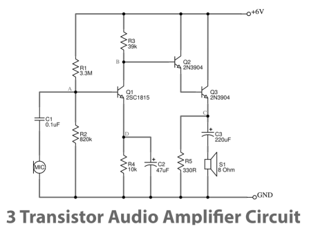
The problem is
the value of the 330R across the speaker.
If we remove it, the electrolytic in series with the speaker will charge when
the emitter rises but will not discharge when the voltage on the emitter
reduces.
This is because the emitter lead does not have any connection to the capacitor
when the voltage on the emitter is reducing.
This is how we see what the transistor is doing. When the voltage on the emitter
is rising, the transistor is like a resistor that is reducing resistance and
more current will flow through it and this current will charge the capacitor.
When the voltage on the emitter is reducing, the transistor is effectively
increasing resistance and less current flows into the capacitor. It never gets
to the situation where the capacitor is discharged.
All that will happen is this: The capacitor will gradually charge on each cycle
and eventually become fully charged.
The circuit works like this: When the capacitor is uncharged, the transistor
turns ON and current flows through the capacitor to charge it. This
charging-current also flows through the speaker to produce sound.
On the next cycle, the capacitor will be slightly charged and so the chagrin
current will be slightly less and the speaker will get less current to move the
diaphragm.
Eventually the capacitor will be fully charged and the speaker will not produce
any sound.
This is because the voltage across the capacitor is equal to the voltage
supplied by the transistor. When this occurs there is no extra voltage for the
“charging-process.”
Not w we add the 330R resistor.
One the first half cycle of the demonstration, the capacitor will be charged a
small amount. During the rest of the first cycle we want the capacitor to be
discharged so that is can be charged again. But to discharge it we need the
discharging resistor to be the same value as the charging resistor. The charging
resistor is the 8R speaker. So we want the discharging resistor to be 8R also.
The only way to get this is with a zero ohm wire from the top of the capacitor
to the 0v rail. This is called a short circuit and we cannot provide this. The
best we can provide is a low value resistor of about 8R to 10R. This means the
best we can do is half-discharge the capacitor. And it means current will be
flowing through the resistor during both halves of the cycle. Current will flow
through this resistor when the circuit is supplying current to the speaker and
the circuit immediately becomes less than 50% efficient.
The discharge will be the ratio of 8R to 330R and is something less than 3%.
That’s why this arrangement is so bad.
The way the electrolytic works is this: When it is uncharged, it acts like
a low resistance resistor that connects the emitter to the speaker. When it goes
high, the cone of the speaker responds. When it goes LOW, the cone returns to
its rest position. But when the electrolytic charges, the slight voltage across
its terminals DETRACTS from the rising voltage. This reduces the output from the
speaker. If the electrolytic charges fully, the speaker gets no increase in
current and the cone does not respond.
If the electrolytic is not discharged fully on each cycle it will gradually
charge and the sound from the speaker will get weaker and weaker.
Here is another circuit with the same fault. No-one on the web builds any
of the circuits they show in their blogs.
RAIN ALARM
Answer below
Once again ETron sent me one of their mass mailings and l replied to them saying
l commented on their educational site some years ago.
heap” and untouchable.
HOW TO USE A SOLDERLESS CIRCUIT BOARD? Where do you get the "?"
Obviously from a non-intelligent writer. And where do you get this
old-style breadboard??? It disappeared from the market 30 years ago.
This is another example of what not to teach.
This is because the emitter will only start to pull the electrolytic up when the
voltage is nearly at the maximum because the electrolytic already has a voltage
across it. And this voltage detracts from the effectiveness of the transistor.
When the capacitor is fully charged the emitter of the transistor will not be
able to pull the capacitor up AT ALL.
We have already said the emitter has no ability to push down on the capacitor
and the only thing that will discharge the capacitor is a resistor across it to
the 0v rail.
The most effective value is 8R or less and since this will pass the same amount
of current as the speaker, you might as well connect the speaker directly to the
emitter and remove the capacitor.
This will solve all the problems as it will take no more current and deliver the
maximum output.
There was no reason to add the capacitor. It did nothing and only created
problems.
But you have to design the circuit slightly differently if you don't want "set
the cone." This is the term used for reducing the current through the coil when
it is directly coupled. The signal has to range from very low to a maximum. It
cannot range from "quite a bit" to "a lot." This will put current through
the coil all the time a "SHIFT IT" from its rest position.
This adjustment is made by turning ON the first transistor quite a lot so the
collector voltage is about 1.8v. This will make the emitter voltage of the
emitter-follower transistor less than 06v and cause very little current to flow
in the speaker coil.
You have to go through each component and work out what it is doing and if it is
necessary. And if you can improve things.
It’s called: THINKING OUTSIDE THE BOX.
The 560R to 100R ratio will deliver less than 10%.
And the 10k to the electret microphone should be 100k for 12v
supply. 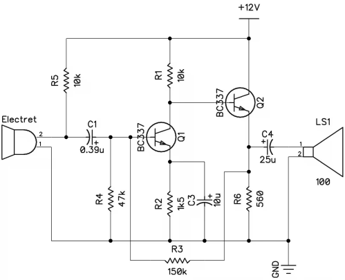
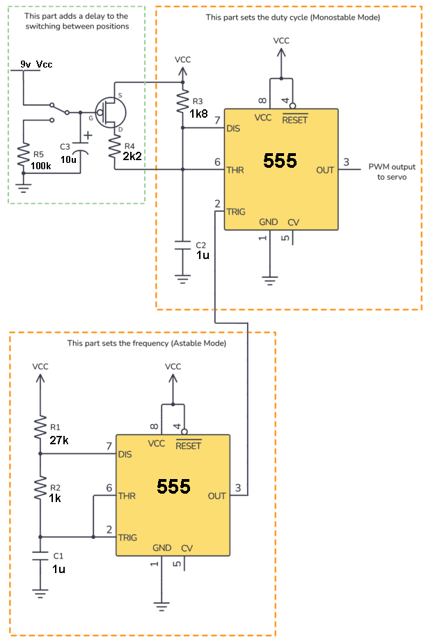
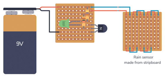
Here is a circuit from BUILD ELECTRONICS CIRCUITS by Oyvind.
The layout contains a mistake. Can you find it? 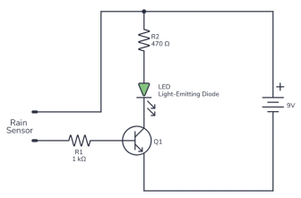

I noted that nothing has changed. Their site still contains all the same faults
and they have no intention of fixing anything.
This is typical of the American attitude. They think they are the “top of the 
And that’s exactly right. They are so untouchable that they now rank very low on
the scale of intelligence and education.
And it’s declining at a rapid rate. In 50 years l have not received an
intelligent email from an American on an electronics subject.
In fact l have to make sure buyers of my products know what they are buying and
how to use them, because they are totally adrift of what they are buying.
How would they know? Where have they got their electronics understanding from?
Not one of my hundreds of electronics projects and modules has been copied by an
electronics manufacturer in America.
That’s a clear indication of their incompetence.
When you have ETron dishing up out-of-date circuits with no explanation of how
they work, on breadboard pictures l cannot follow, how can you expect a newcomer
to get any training?
Obviously he learns nothing and this has been passed down for the past 50 years
and the result is clear.
America produces NOTHING.
Not even the ability of delivering and educational electronics course.
The reply l got from ETron was: “let’s agree to disagree.” That’s what your
instructor thinks of you. A FOOL.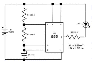
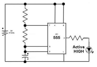
The LED is illuminated when the output of the 555 is LOW.
This is called ACTIVE LOW and although there is nothing wrong with this activation,
when you come to fault-find the board, you cant remember if the LED is around
the wrong way or it gets activated with a LOW signal.
Stick to ACTIVATION HIGH.
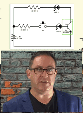
Here is
your instructor with his up-side-down circuit, showing ??????
Here is the circuit correctly drawn. It is supposed to show a small current via
the base and a larger current via the emitter by the fact that the LEDs
illuminate with different brightness. But HIGH BRIGHTNESS LEDs will illuminate
with very little current and this demonstration will show nothing.
I have no idea what he is showing. I don't understand up-side-down
circuits.
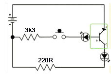
A circuit is an instantaneous picture. It is not to be turned-around or held
up-side-down. If you can't see what is happening, you need to find out who is
drawing the circuit. It looks like a BEGINNER.
You can get all the components for a fraction of the cost from Chinese suppliers
such as Aliexpress or eBay and look on the web for hundreds of circuits.
There are also many free courses but none of them explain anything and are
construction projects without any learning.
This is generally the case because very few people understand how a circuit
works and even fewer know how to write a technical description.
ETron is a typical example of a course containing more mistakes than you can
“poke a stick at.”
It is so bad that l could not even give it a beginning rating. It has a value
less than zero.
It ranks in my “Spot the Mistake” as a learning curve to teach you how not to
design a circuit.
And for that reason l have included it here.
You can also get my previous comments on page 30:
Phase shift oscillator
Going back to the phase shift oscillator, l placed a large discussion on more than 12 sites and after 12 months, not a single person has posted a comment about my discussion.
It is obvious that no-one believes what they have been taught is totally false. Totally inaccurate and cannot be backed-up by describing how the circuit actually works.
They all provide a vague comment about 60 degree phase shift on each stage, making 180 degrees of shift. But no-one has explained how the shift occurs. They are using a the shift of a capacitor/resistor network in an entirely different set-up that does not apply to this circuit.
They come to the conclusion that a positive signal can be turned into a negative signal by shifting it 3 times. I can turn lead into gold by converting it to platinum, then silver then tin and eventually gold.
That’s how the Universities work. Mesmerism. Trickery. “Sleight of hand” and “Fool me once, fool me again.”
They use mathematics and equations and totally irrelevant characteristics to bamboozle the visitor and finish up with comments like: “this is the best description l have seen.”
“Snake oil!”
No-one likes to be exposed and as soon as l reply, l am banned. It’s censorship.
I could go on to everything else you have been taught.
But with electronics, the teaching is inaccurate because the lecturers have simply never built anything in their lives.
Have you ever seen a lecturer come in with a model, a project, an example, a prototype of anything he is discussing?
Has he ever shown you his expertise in testing anything?
And especially, has he ever asked a student to create a fault and see how he locates and fixes it!
That’s because they are totally incompetent.
That’s why my kit business to schools failed. In 50 years, not a single school in Australia bought a class set of kits.
Two trade schools bought a set of 20 car alarms. None worked. They sent them back for repair. The soldering was impossible to fix. The parts were standing high off the board. Parts were in the wrong place.
The other set of 25 kits were the same.
These teachers had no idea how to build anything electronic.
And that’s why no other schools bought anything. The teacher could not fix anything.
That’s why l changed to only selling model railway modules and supply them already built and tested.
MAKE
Once again, MAKE have sent me an email from their bulk-emailing list and have
the cheek to send out a promotion of all their old books with the myriad of
mistakes, for an absurd price of over $120.00. They say they have sold over
200,000 of the first edition and that’s 200,000 beginners who have been “lead
down the garden path” and steered in the wrong direction, with the enormous
number of mistakes in these books.
That’s why, overall, sales of kits and projects to American students have been
incredibly low. They are not being taught anything from these books and don’t
understand what they are doing.
Electronics is not a “build it and watch the LED turn on and off.”
This teaches you NOTHING.
After all, our TV’s were made down the road by local women and after 20 years,
they learned nothing about electronics.
The author behind these books has a very little understanding of electronics and
explains nothing about how the circuit works, or how to fault-find.
I have already contacted the author and the publisher and absolutely nothing has
been done to rectify or remove the mistakes or provide an “errata sheet.”
And now they send out another email with edition 2, 3 and 4. But when you go to
the listing you find the edition is an old version.
The same applies with the courses from other “shysters.” Their $100.00 course is
simply old circuits from the web, constructed on bread-board that is no longer
available, with photos that l cannot follow.
In both cases you can get the components from Aliexpress for much less than half
the cost.
I would not complain if the courses provided the slightest amount of
instruction. The slightest amount of learning. The slightest amount of
education.
The problem is they ruin it for genuine kit suppliers. The enthusiasts have
already “had their fingers burned” by these “rouge” shysters and have stopped
buying.
The internet started with lots of “criminals” wanting $30.00 per month to join a
course or data sheet supplier. Eventually this failed and one suppler made the
offer FREE.
All l have done is ask these suppliers to send me a copy of their work so l can
correct the mistakes.
Not a reply.
They have no interest or incentive or intention to improve their “junk.”
There is no-one more stupid than “he who does not see.”
They are so dumb as to be unable to “get out of their own way.”
There is very little need for electronics understanding because most electronics
is built around digital circuitry and modules.
But the problem exists when interfacing a design to an input device.
This is where your knowledge of impedance-matching and programming is
most-needed.
And that’s where the vacuum is.
No course or lecture explains this.
And that’s why you have to go through my hundreds of pages of explanation of how
circuits work, to learn about this.
It is all provided for free and over 25 million visitors have come to the
website.
It is up to you to get involved and create your own projects and products.
And finally, l received an email from a professor, touting his capability in
teaching how to improve your life and business skills.
Remember this. Professors are no better than the worst employee you could ever
imagine.
They are totally incapable and incompetent in this world.
The only thing they are good at it is: REMEMBERING.
They are “parrots.” They simply regurgitate what they have been taught.
I am mainly talking about the electronics industry where you need to understand.
With mechanical engineering you can see what you are doing. Electronics is
invisible. You have to understand. That’s why it is one of the highest
disciplines.
And in that regard l have not seen a single lecture where the professor has
explained anything at all level that the beginner can understand.
They have no concept of “thinking outside the box.” Come down “three rungs of
the ladder” and say: “this pushes UP, this pushes DOWN.” Forget mathematics,
forget microscopic differences. Forget calculating to the “n’th” degree.
Get the message across with a huge prototype showing the transistor operating.
This might cost $2.45. But “hang the expense.” Throw all your money into the
demonstration. Get your lecture across.
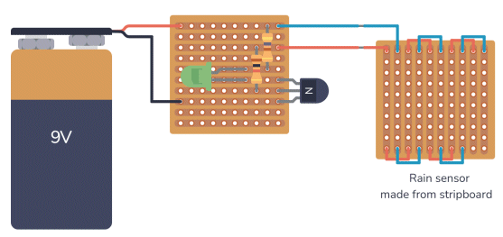
The correct layout from the discussion above
Page 1
Page 2
Page 3
Page 4
Page 5
Page 6
Page 7
Page 8
Page 9
Page 10
Page 11
Page 12
Page 13
Page 14
Page 15
Page 16
Page 17
Page 18
Page 19
Page 20
Page 21
Page 22
Page 23
Page 24
Page 25
Page 26
Page 27
Page 28
Page 29
Page 30
Page 31
Page 32
Page 33
Page 34
Page 35